

$ 10,000 question


Thread Starter
Senior Member
Joined: Jan 2002
Posts: 943
Likes: 0
From: Chesapeake Va
$ 10,000 question
heres what I'v got:
86 T-A
305 ccc-4BBl (not the high output)
700R4
gutted cat.
straight pipes
the motor and tranny only have about 4,000 miles on them,
I have tried everything I can think of and can't figure out what is wrong, there is a verrrrry strong gas smell comming from the exhaust, heres what I have done so far:
newer O2 sensor (4,000 miles on it)
timing set to 0 degrees without the computer (4 pin connector unplugged)
IAB set to 30 on the dwell meter on the 6 cyl. setting
choke flaps all the way open
motor warmed up (220 degrees)
mainfold vacuum at 19 hg. (steady) at 600 rpm in park
tps reads .58 and the VOM at idle
rebuilt carb (plugs in bottom plate epoxied over, the ones that always leak)
tweaked secondary air valves (per tech article tips)
If anyone has any Ideas I would reallllly appreciate the input, I'm tired of gagging and gas fumes
Moderator


Joined: Jan 2000
Posts: 19,658
Likes: 310
RedBird,
You took all the fun out of this one. You've covered all the initial things I would have suggested - the well plugs on the bottom of the E4ME, the TPS voltage, MC solenoid adjustment, O� sensor, choke, whatever...
Everything looks tight, from the TPS to the vacuum readings. The engine seems plenty warm. It is possible that the gutted cat is allowing some HCs to exhaust, or the lack of A.I.R. is not completing combustion, but the O� sensor should detect and correct that for the most part. Do you have a means to scan for active O� data? That may tell you whether the mixture is correct and your nose is sensitive, or if you are truly too rich. If not, you may be able to find a shop with an older Sun 720 or 920 that can sniff the exhaust and display the mixture results.
It's also possible that the ECM is not getting correct CTS data, and is skewing the mixture rich for a presumed cold engine. Just a possibility.
Last edited by Vader; Feb 10, 2002 at 05:25 PM.
Thread Starter
Senior Member
Joined: Jan 2002
Posts: 943
Likes: 0
From: Chesapeake Va
thanks for responding vader,
I forgot to mention that the coolant temp sensor has been replaced already. I do not have a scan tool and don't know of anyone who does, is there a way to check the O2 sensor with common tools or does it take special scanners. I heard of a program called winaldl (or something lik that) that you run on a laptop, would that help with the diagnosis. if so, where can I find the perticulars on the needed supplies to make it work.
P.S. I don't thinks it my nose because I work in a chemical plant and my sense of smell has dulled somewhat and my wife complains about it also.
thanks to all who have helped me !!!!!!!!!!!
Thread Starter
Senior Member
Joined: Jan 2002
Posts: 943
Likes: 0
From: Chesapeake Va
I forgot to ask,
there is some sort of sensor mounted near the firewall on the passenger side of the bay (right between the A/C box and the engine), it has a vacuum line going to it and a weatherpack connector with 3 or 4 wires going to it. what is this sensor and could it be part of the problem ?????
there is some sort of sensor mounted near the firewall on the passenger side of the bay (right between the A/C box and the engine), it has a vacuum line going to it and a weatherpack connector with 3 or 4 wires going to it. what is this sensor and could it be part of the problem ?????

Supreme Member
Joined: Jul 2000
Posts: 1,341
Likes: 0
From: Where the chicks absolutely LOVE the V-8 rumble!
Car: 92 RS - Fully Restored w/Custom Int
Engine: LO3 with some mods
Transmission: T-5
Axle/Gears: 3.42 Richmond
On a TBI engine that sounds like where your Manifold Absolute Pressure (MAP) sensor is supposed to be.
If you car uses an ECM then it is most likely required.
If you car uses an ECM then it is most likely required.
Moderator
Joined: Jan 2000
Posts: 19,658
Likes: 310
Pukka is right. The MAP is used in conjunction with the TPS and engine RPM data to determine engine load and appropriate mixture. If the MAP is sending a high pressure signal (low manifold vacuum) the ECM would presume a heavy load and tend to enrich the mixture to compensate.
Of course, the hose connecting the sensor to the intake manifold needs to be intact, free from cracks, leaks, splits, or kinks. The electrical connector needs to be clean and tightly seated.
The MAP sensor can be checked with a vacuum source and a digital voltmeter. The sensor should output a 0-5VDC signal at the 'B' terminal. The output voltage is based on absolute pressure at the hose connection. The sensor should output full voltage (5.0VDC) when there is one BAR (barometer, or atmosphere) of pressure applied. This means there is basically no vacuum (0" Hg) and the Absolute Pressure is at 14.7 PSIA.
When the Absolute Pressure decreases (due to vacuum) the voltage output on the 'B' terminal should decrease as well. Test the sensor down to about 20" Hg of vacuum, or 0.33 BAR (4.9 PSIA), where the output voltage should be aroud 0.8-1.2 VDC. The voltage should vary in direct proportion to the Absolute Pressure, or amount of vacuum applied. If the MAP output "jumps" or "sticks" at a given point, the sensor bridge circuit or the mechanical diaphragm is failing. Since there is no good way to repair a MAP sensor, replacement would be indicated.
By these tests, normal idle vacuum of 18" Hg should produce about 1.2-1.5 VDC.
You can test the O� output with a DVM as well, but unless you have a really fast DVM the readings may not be accurate. Beyond that, the connection is not easy, and adding any resistive load to the sensor circuit can skew the readings, even teh relatively high impedance of a DMM can change it slightly.
It might be easier to use the ECM in Field Service Mode to determine if the ECM thinks the mixture is rich or lean. This may be a good idea anyway, since even if the ECM is electrically duty-cycling the MC solenoid at the presumed 50%, the solenoid may not compliant and the mixture may not be changing as you would expect.
Field Service Mode
On the OBDI ECMs, you can jump 'A' and 'B' terminals on the ALDL while the engine is running.
WARNING! This must be done after the engine is running. This is called "Field Service Mode" and will not harm the ECM.
If the ECM is in Open-Loop mode, the SES light will flash rapidly, about 2� times per second. If it's in Closed-Loop mode, it will flash about once per second. When in Closed Loop mode, flashing less than once per second indicates the ECM is enriching the mixture above the 128 count base line. Flashing more than once per second indicates the ECM is leaning the mixture below the 128 base line.
Good luck.
Thread Starter
Senior Member
Joined: Jan 2002
Posts: 943
Likes: 0
From: Chesapeake Va
ALRIGHT !!!!!!!!
I checked the map sensor with a VOM and got4.7 volts with engine off, started engine (21" hg) and got 4.7 volts. started checking hose routing and think the hose was hooked to the wrong place. hooked it up to the port on the back of the manifold (between the carb and the dist.) and got .90 volts. noticed right away that the gas smell was gone, had to readjust the IAB to get the setting right again.
I noticed that with the engine running the map sensor reading was jumping all over the place (.90 - 14.????) I think I'll replace it just for safe measure.
P.S. if anyone has a schematic or scetch of the vacuum routing on a 86 T-A can you please send it to me so I can check my other plumbing???
THANKS TO ALL WHO HELPED ------ YOU ARE WHY THIS BOARD IS GREAT !!!!!!!!!!!!!!!!!!
Trending Topics
Thread Starter
Senior Member
Joined: Jan 2002
Posts: 943
Likes: 0
From: Chesapeake Va
Why can"t GM be clear about theyre sensors ?????
I have two sensors that look alike, one is mounted to the firewall between the engine and the A/C box (I think this is the MAP sensor), the other is mounted on the firewall on the drivers side closest to the fender (what is this and what does it do).
I have a haynes book which shows the (map sensor in the 1st location as being for a TPI CAR and the sensor in the second location as being a BARO sensor for a carb. car, my car is carb'd. but I have both sensors. is there something I missed ??????
please help ????????????????
Moderator
Joined: Jan 2000
Posts: 19,658
Likes: 310
RedBird,
This is one I have for a E4ME setup, without the BARO sensor (since there is no vacuu, connection to it!) so it should be close:
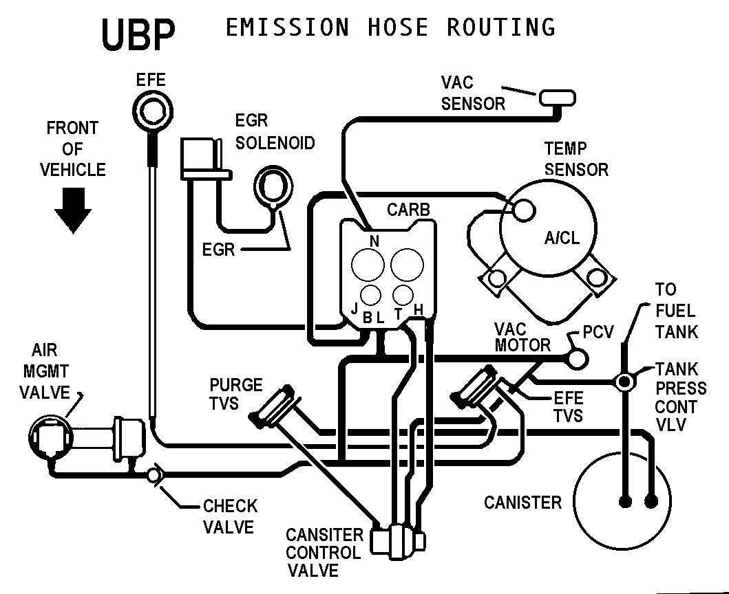
GM does identify their sensors in a manner of speaking, through the wire harness coloring. The Haynes manual is probably better than nothing, but there are more complete references available that cover the information in much more detail and with more clarity.
This is one I have for a E4ME setup, without the BARO sensor (since there is no vacuu, connection to it!) so it should be close:
GM does identify their sensors in a manner of speaking, through the wire harness coloring. The Haynes manual is probably better than nothing, but there are more complete references available that cover the information in much more detail and with more clarity.
Last edited by Vader; Aug 29, 2021 at 10:52 AM. Reason: Updated Links
Thread Starter
Senior Member
Joined: Jan 2002
Posts: 943
Likes: 0
From: Chesapeake Va
Went to chevy today,
the sensor on the driverside of firewall is called a vacuum sensor or differential pressure sensor (listed in Haynes book as MAP sensor) tested no vacuum at .61 volts and engine running (20" hg at 4.17 volts) is this right ??
the sensor on the passenger side of the engine is called the BARO sensor and has no vacuum source applied (tested at 4.7 volts) all the time. is this right ?????
thanks again !!!!!!!!!!!

Thread
Thread Starter
Forum
Replies
Last Post