Indicator lights for cooling fans
 01-03-2014, 08:27 AM
#1
Supreme Member

Thread Starter

Indicator lights for cooling fans
I want to be able to have indicator lights in my driving compartment to make sure cooling fans are running. I have a two speed cooling fan behind the radiator on my 83 Camaro. Have install LED's in the cabin and have ran wires out to the relays. Have separate relays for low and high speed.Want to wire it so the lights are on, one for low speed and one for high speed. These need to be on the power side to the fan motor for high and low speeds. Now here is the problem, all wired up and when fan is on low speed both high and low speed indicator lights are on. Same for the high speed. Do I need to install a diode some where inline to keep power from bleeding through and lighting both indicator lights at the same time?
 01-03-2014, 08:42 AM
#2
Member
iTrader: (2)

Join Date: Sep 2013
Location: Buffalo, NY
Posts: 345
Likes: 0
Received 1 Like
on
1 Post
Car: 85 Silver Iroc, 79 Camaro
Engine: LB9, 500+ ci BBC
Transmission: 700R4, th400 with brake
Axle/Gears: 3.42, hand made 40 spline 9"
Re: Indicator lights for cooling fans
If you grounded both lights to the same point, they're probably back feeding each other.
01-03-2014, 09:26 AM
#3
Supreme Member
Thread Starter
Re: Indicator lights for cooling fans
I have so many grounds on my car that I am afraid where ever I ground them I will get feedback. Hay that gives me an idea though. What kind of diode could I put inline on the ground to stop this?
01-03-2014, 09:38 AM
#4
Member
iTrader: (2)
Join Date: Sep 2013
Location: Buffalo, NY
Posts: 345
Likes: 0
Received 1 Like
on
1 Post
Car: 85 Silver Iroc, 79 Camaro
Engine: LB9, 500+ ci BBC
Transmission: 700R4, th400 with brake
Axle/Gears: 3.42, hand made 40 spline 9"
Re: Indicator lights for cooling fans
I'd have to do some digging to figure it out.
Maybe Tuned Performance could help you out.
Maybe Tuned Performance could help you out.
01-03-2014, 10:08 AM
#5
Supreme Member
Thread Starter
Re: Indicator lights for cooling fans
Working on this project today, has anyone ran into this problem before?
01-03-2014, 10:23 AM
#6
Re: Indicator lights for cooling fans
Did you wire them to the trigger wires for the relay instead of the hot wires for the fan? It won't tell you if the fan is getting power that way, only that they should be.
01-03-2014, 10:51 AM
#7
Supreme Member
Thread Starter
Re: Indicator lights for cooling fans
They are wired to the power wire for the fan motor itself. This will let me know that the fan motor is getting power and should be running unless the fan motor itself goes bad.
Trending Topics
01-03-2014, 11:03 AM
#8
Re: Indicator lights for cooling fans
Wiring to the trigger wires will do the same thing, just won't tell you if the relay is not working. Maybe hook one LED up to the supply to the fan, and the other to the trigger wire for the other relay. That should keep the circuits separate and still assure you the fan is getting power.
01-03-2014, 11:46 AM
#9
Supreme Member
Thread Starter
Re: Indicator lights for cooling fans
Joe I can give that a shot but my idea was to be able to tell that both the low and high speed relays were sending power to the fan, depending on demand of engine temperature. I am going to head out to my shop and I will make a jumper wire and try out your idea. Thanks for your input.
01-03-2014, 11:57 AM
#10
Re: Indicator lights for cooling fans
Well my thought on the diodes is the bottleneck that is created by the smaller wire. It no doubt is feeding back through the hot not the ground. Possibly several diodes in parallel will work and not have much resistance.
01-03-2014, 12:50 PM
#11
Member
iTrader: (2)
Join Date: Sep 2013
Location: Buffalo, NY
Posts: 345
Likes: 0
Received 1 Like
on
1 Post
Car: 85 Silver Iroc, 79 Camaro
Engine: LB9, 500+ ci BBC
Transmission: 700R4, th400 with brake
Axle/Gears: 3.42, hand made 40 spline 9"
Re: Indicator lights for cooling fans
An LED is polarity specific. I guess I missed that on the original thread.
You've got something wired up wrong or something.
LED = light emitting diode
A diode will only work right if the polarity is correct.
Are you sure it's not a bulb I that light? I've seen things at Radio Shack labeled wrong.
Not saying you're wrong, just saying sometimes things are mislabeled.
You've got something wired up wrong or something.
LED = light emitting diode
A diode will only work right if the polarity is correct.
Are you sure it's not a bulb I that light? I've seen things at Radio Shack labeled wrong.
Not saying you're wrong, just saying sometimes things are mislabeled.
01-03-2014, 01:37 PM
#12
Re: Indicator lights for cooling fans
I doubt it's wired wrong, this is pretty normal for a light (LED or incandescent), when connected to a motor.
I bet you'll find that the LEDs will indicate the fans are on, even when the relays are off and you're driving above 40 MPH or so. A motor not only takes in electricpower and converts it to kinetic energy, but can also take kinetic energy and turn it into electric power. This is why both LEDs come on even when only one relay is triggered. The motion of the fan is acting upon the windings and producing electric power, that is being transferred to the LED via the wired connection to the fan. The only way to stop that from happening is to isolate the fan from the LED connection. I don't recommend it, but a large diode that can pass several tens or hundreds of amps could be used. The problem here is that regardless of the size of diode, you will get a .6 to .7 volt drop across the diode (Silicon) or .3V (Germanium), though I'm not sure I've seen a germanium diode that would fit the application.
The best you can really hope for here is that you will have an indicator that will tell you if the fan is spinning (not necessarily powered), because of how electrical energy is produced is in this set-up. You could install those diodes, though they will be pricey to be large enough, and you will get that voltage drop, that would do exactly what you want, with degraded performance of the fan(s).
I can't think of a simple way to make this work without having the voltage drop, I do have an idea, but would need to test before I would be comfortable suggesting that it will work without messing with the control part of the circuit.
I bet you'll find that the LEDs will indicate the fans are on, even when the relays are off and you're driving above 40 MPH or so.
A motor not only takes in electricpower and converts it to kinetic energy, but can also take kinetic energy and turn it into electric power. This is why both LEDs come on even when only one relay is triggered. The motion of the fan is acting upon the windings and producing electric power, that is being transferred to the LED via the wired connection to the fan. The only way to stop that from happening is to isolate the fan from the LED connection. I don't recommend it, but a large diode that can pass several tens or hundreds of amps could be used. The problem here is that regardless of the size of diode, you will get a .6 to .7 volt drop across the diode (Silicon) or .3V (Germanium), though I'm not sure I've seen a germanium diode that would fit the application.The best you can really hope for here is that you will have an indicator that will tell you if the fan is spinning (not necessarily powered), because of how electrical energy is produced is in this set-up. You could install those diodes, though they will be pricey to be large enough, and you will get that voltage drop, that would do exactly what you want, with degraded performance of the fan(s).
I can't think of a simple way to make this work without having the voltage drop, I do have an idea, but would need to test before I would be comfortable suggesting that it will work without messing with the control part of the circuit.
01-03-2014, 02:54 PM
#13
Supreme Member
Thread Starter
Re: Indicator lights for cooling fans
I agree with the wire size on a single diode being a huge bottle neck.
01-03-2014, 02:55 PM
#14
Supreme Member
Thread Starter
Re: Indicator lights for cooling fans
I believe the polarity on the LED'S is correct.
01-03-2014, 03:02 PM
#15
Supreme Member
Thread Starter
Re: Indicator lights for cooling fans
Six shooter is on the mark on this project. The motor is indeed generating enough electrical current to light both LED'S Sooooooo I just got back in from the shop and have rewired to the trigger wire on the solenoids. I guess this will have to do. At least I will know the solenoids are getting voltage. Thanks to all for your input.
01-03-2014, 04:57 PM
#16
Re: Indicator lights for cooling fans
It's not the connector or wire size on the diode dropping the voltage, it's the silicon properties that requires a Vf (Forward Voltage) of .6 to .7V in order for the diode to "turn on", and allow voltage to pass. This is what causes the .6 to .7V drop across a silicon diode.
01-03-2014, 06:52 PM
#17
Supreme Member
Thread Starter
Re: Indicator lights for cooling fans
Oh alright then, learn something every day. Thanks for the help.
01-04-2014, 01:22 PM
#18
Member
iTrader: (2)
Join Date: Sep 2013
Location: Buffalo, NY
Posts: 345
Likes: 0
Received 1 Like
on
1 Post
Car: 85 Silver Iroc, 79 Camaro
Engine: LB9, 500+ ci BBC
Transmission: 700R4, th400 with brake
Axle/Gears: 3.42, hand made 40 spline 9"
Re: Indicator lights for cooling fans
What about tapping into the feed on the relay instead of the output on the relay. I know this would mean that only the relay is getting power, but that would isolate the LED from the fan.
You could also wire in a relay using the fan output, as wired, to feed a relay to trigger the indicators. There wouldn't be enough feed back current from the fan to trip the relay.
I'd like to tackle this wiring job. This would be a fun one to figure out for sure.
You could also wire in a relay using the fan output, as wired, to feed a relay to trigger the indicators. There wouldn't be enough feed back current from the fan to trip the relay.
I'd like to tackle this wiring job. This would be a fun one to figure out for sure.
01-04-2014, 04:24 PM
#19
Senior Member
iTrader: (5)

Join Date: Jan 2009
Location: Golden, CO
Posts: 887
Likes: 0
Received 11 Likes
on
9 Posts
Car: 87 IROC
Engine: L31 350
Transmission: T56
Axle/Gears: 4.10 D44
Re: Indicator lights for cooling fans

When the high speed relay kicks in, obvious the high LED lights, and the low LED will get ~50% Voltage from the middle of the motor windings, which is enough to light.
You can put a high power diode between the high speed relay and the high speed fan wire, with the LED on the relay side of the diode. This will block the back flow from the motor, and allow forward (high) current to run the motor.
01-04-2014, 05:35 PM
#20
Supreme Member
Thread Starter
Re: Indicator lights for cooling fans
Where might I be able to find one of these diodes and how will I be able to identify it? Would there be I.D. numbers or what? Thanks for your input.
01-05-2014, 09:02 AM
#21
Senior Member
iTrader: (5)
Join Date: Jan 2009
Location: Golden, CO
Posts: 887
Likes: 0
Received 11 Likes
on
9 Posts
Car: 87 IROC
Engine: L31 350
Transmission: T56
Axle/Gears: 4.10 D44
Re: Indicator lights for cooling fans
A quick look at Mouser.com, I filtered on 40A forward current, and the lowest Voltage drop is 2.7V, which will significantly reduce power to the fan.
I think this is a bad solution.
I think this is a bad solution.
01-05-2014, 09:47 AM
#22
Supreme Member
Thread Starter
Re: Indicator lights for cooling fans
I agree, I do not like this solution either. I need the fan running at peak performance with the rat motor stuffed in there.
01-06-2014, 05:27 PM
#23
Supreme Member
Join Date: Jan 2006
Location: Mooresville NC
Posts: 3,341
Likes: 0
Received 10 Likes
on
10 Posts
Car: LOWERED ♦ CRIMSON METALFLAKE
Engine: ► 400 KUBES ◄
Transmission: 765R4
Axle/Gears: EATON POSI 4.56
Fantastic Fan Plan
Because you first you state you have 2 fans, then you state 1 Two-Speed fan this information is slightly generic.
A more informative solution would be to wire an indicator light across each relay coil
(which was first mentioned by Joe Tag), AND one each across the fan input wires.
Then you will know which relay has been called for activation, AND if the fan is getting power.
To prevent the fan generated voltage from illuminating the �Power Received At Fan� light, IF that happens, use additional relays as in the supplied diagram.
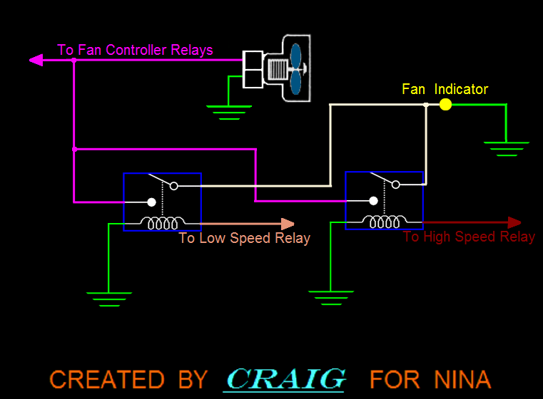
If you have 1 Two-Speed fan you can use 2 circuits (1 circuit for each power input).
You can use tiny relays due to the low current requirements of the indicator lights.
Not recommended, due to the fact the loss of .7 volts causes an accompanying current drop.
You will lose 13% power to the fan.
Yes that is a viable way to go for the �Fan Is Receiving Power� LED.
Probably not, but keep in mind it takes less power to KEEP the relay energized, but hopefully it won�t stay energized.
However if it does the above diagram solves that problem.
▬▬▬▬▬▬▬▬▬▬▬▬▬▬▬▬▬▬▬▬▬▬▬▬▬▬▬▬▬▬▬▬▬▬▬▬
Now remember Ed, the original plan you had in mind doesn�t tell you if the fan is spinning.
Therefore you might want to upgrade to IR♦LEDS.
You can mount one infrared LED transmitter on one side of the fan, and one infrared LED on the other side of the fan.
The IR♦LEDS can be mounted on brackets, or in the fan shroud, then you add an interpreter.
Now, when the fan spins the interruption of the IR♦LED path will go to the interpreter unit, then the interpreter unit will illuminate the ☼ Fan Spinning LED in the cockpit.
The interpreter should be settable to a minimum frequency therefore won�t give a false response due the fan coasting from wind.
◙◙◙◙◙◙◙◙◙◙◙◙◙◙◙
Happy Racing!
◙◙◙◙◙◙◙◙◙◙◙◙◙◙◙
I�ll Bump You Once To Move You Over, Next Time I�ll Spin You
A more informative solution would be to wire an indicator light across each relay coil
(which was first mentioned by Joe Tag), AND one each across the fan input wires.
Then you will know which relay has been called for activation, AND if the fan is getting power.
To prevent the fan generated voltage from illuminating the �Power Received At Fan� light, IF that happens, use additional relays as in the supplied diagram.
If you have 1 Two-Speed fan you can use 2 circuits (1 circuit for each power input).
You can use tiny relays due to the low current requirements of the indicator lights.
Originally Posted by MoJoe
��.put a high power diode between the high speed relay and the high speed fan wire��.
You will lose 13% power to the fan.
Originally Posted by Jonesyfxr
You could also wire in a relay using the fan output, as wired, to feed a relay to trigger the indicators.
Originally Posted by Jonesyfxr
There wouldn't be enough feed back current from the fan to trip the relay.
However if it does the above diagram solves that problem.
▬▬▬▬▬▬▬▬▬▬▬▬▬▬▬▬▬▬▬▬▬▬▬▬▬▬▬▬▬▬▬▬▬▬▬▬
Now remember Ed, the original plan you had in mind doesn�t tell you if the fan is spinning.
Therefore you might want to upgrade to IR♦LEDS.
You can mount one infrared LED transmitter on one side of the fan, and one infrared LED on the other side of the fan.
The IR♦LEDS can be mounted on brackets, or in the fan shroud, then you add an interpreter.
Now, when the fan spins the interruption of the IR♦LED path will go to the interpreter unit, then the interpreter unit will illuminate the ☼ Fan Spinning LED in the cockpit.
The interpreter should be settable to a minimum frequency therefore won�t give a false response due the fan coasting from wind.
◙◙◙◙◙◙◙◙◙◙◙◙◙◙◙
Happy Racing!
◙◙◙◙◙◙◙◙◙◙◙◙◙◙◙
I�ll Bump You Once To Move You Over, Next Time I�ll Spin You
01-22-2014, 09:56 AM
#24
Supreme Member
Join Date: Jun 2000
Location: VA
Posts: 1,295
Likes: 0
Received 0 Likes
on
0 Posts
Car: '91 Z28
Engine: L98 5.7L TPI
Transmission: 700R4
Axle/Gears: 323's
Re: Indicator lights for cooling fans
i put indicator lites on my dash years ago and simply ran the "+" (for the light) to a key on source and the grounds to the fan circuits so once the circuit is grounded to turn the fan(s) on, it also completes the circuit to the light on the dash. simple. no diodes or anything else - just a bit of wire and connectors...
Last edited by thunderstick; 01-22-2014 at 09:58 AM. Reason: edit

Thread
Thread Starter
Forum
Replies
Last Post
ambainb
Camaros for Sale
11
04-25-2016 09:21 PM
Hellbillydeluxe
Tech / General Engine
10
09-22-2015 09:58 PM