When you click on links to various merchants on this site and make a purchase, this can result in this site earning a commission. Affiliate programs and affiliations include, but are not limited to, the eBay Partner Network.
Even tho, mine just clicks it doesn't make a 'beep' as their does.
At first just tried to use a no load flasher from the auto parts store, but it didn't work. So I search and found this one, and it seems to work with both LED and/or bulbs in the circuit.
Even tho, mine just clicks it doesn't make a 'beep' as their does.
At first just tried to use a no load flasher from the auto parts store, but it didn't work. So I search and found this one, and it seems to work with both LED and/or bulbs in the circuit.
Did you use the EL98 or the EL98N? Also did you have to change your hazard flasher?
I just realized that I used zener diodes instead of rectifier diodes. Think this will cause any problems?
And I just dont get it. For the front part of the wrap arounds, I had to do 2 arrays of 4 since I had 8 LEDs left over after I did all the rest in arrays of 5. I used the LED calculator, and it told me to use a 68 ohm resistor (5 LEDs used a 33 ohm). On both boards, the two 4-LED arrays are somewhat brighter than the rest. I went back and actually made the front part of the wrap arounds the same as the tail/brake boards, and when in tail mode, you can definitely tell a difference between the 4-LED and 5LED arrays. When brake is applied, the 4-LED arrays get a little more brighter, but are essentially the same brightness as when in tail mode. Any ideas? I might try getting some 5-10 ohm resistors to try and balance out, but the math tells me that I have the correct resistors...? Here's a quick MS paint on how I got it all wired up. Im a little OCD with this project, can ya tell? lol
I see the 'problem' with your varying brightness.
The calculator I have on my website (http://www.hioutput.com/tech/circuits/resistance.html) shows the actual value needed as well as the next higher 'standard' value.
The 5-LED array shows 28.6 ohms being optimal; the next standard value is 33 ohms, which is about a 15% difference.
For the 4-LED array, it shows 65.7 ohms as optimal with 68 being the next standard value, which is like a 3% difference.
If you had something like a 74 or 75 ohm to use instead of the 68, that would bring them closer together.
And definitely switch out those Zeners! I would use some 1N5401 which have a 5-amp rating.
BTW.....good work on both your parts...nice to see someone pioneering a better way
Figured I'd throw in a few more pics. The first time around on the wraparounds, I basically used some uninsulated steel wire to make all the jumper connections and to connect the circuits to the power and ground wires. Well, upon installing them to the lens, and then into the housings, I found out that it's pretty tight tolerances in there. The housing and lens sandwiched the uninsulated wires and caused all sort of shorts (nothing burned out, thank God). So I took them back out and DID IT RIGHT THE FIRST TIME!! Here's how I had originally had it. The green looking globs is actually caulk where I had originally tried to insulate the wires where it looked like it was touching.
And here is how it SHOULD HAVE BEEN DONE in the first place!! It was a little more intricate trying to snake the wires around the board, but not impossible. Turned out really well I think, and it should install easy with no problems like I had before.
P.S. Your setup is still a big time favorite of mine, beats both Classic and Spaghetti's led kits IMO. Well take care, and how is that going as far as on the car and working?
P.S. Your setup is still a big time favorite of mine, beats both Classic and Spaghetti's led kits IMO. Well take care, and how is that going as far as on the car and working?
I haven't really done anything with the car since late last summer, we got the old 6 out of it. This summer going to start cleaning up the engine bay, and be on the look out for a donor Z28 for parts.
Hopefully I'll make some progress with it, and get the car back to my house
give me a rough idea of what you would want to do a set? i dont have the skills to do this i never got into soldering. its just time my poor camaro got a facelift.
I can speak from experience, it took me a good 2 weeks to get mine completely ready to go, and that included many many MANY trial and errors, and chasing my tail on short circuits on the board (uninsulated wires, doh!) I couldn't imagine charging less than $800/set, and even then I wouldn't want to because you can basically get the same thing for cheaper from SE, and I'm sure they are set up with jigs and all for (semi) mass production. I didn't wanna spend the money on them, plus these DIY tails have gotten a lot of notice, especially since it wasn't bought off the shelf
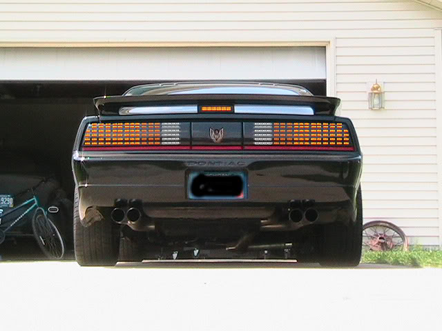
Just wanted to add a little update, after all this time the car has finally been painted and the rear lights have been installed. wanted to add a pic to see the final results.
Also I've decided to redo the front turns, I just didn't care too much with how those turned out. So I opened them back up, and this time. I have 2 boards inside, each at an angle going toward the back of the housing. This allowed me to install the factory diffuser back into the housing. With the lights off, it looks totally factory. With them on, they are much brighter, and have that instant on/off look. You don't see the individual LED like version 1 had, but I think overall I like these better. I'm going to be installing these this weekend, and I'll add more pics once I do.
Got the front LED turns put in today.
I forgot about a couple issues with the front. The side markers work of off some type of alternating ground that's how they work opposite the front when you have your turn signal on. So when you go to LEDs on the front, nothing works right. I believe what I decided to do way back when was to just rewire the side markers to just flash at the same time as the fronts. I'll have to do that later, for not I just don't have a bulb in them.
[quote=ghettocruiser;3539643]cdoyle: Hope you dont mind... I whipped up something in photoshop just fooling around... I think you could get 3 LEDs in each little square in the grid. Reverse could just be straight rows.
This pic would be lights on, brakes applied, and in reverse. Its not my car (hope owner doesnt mind) and the pic wasnt hi res enough to do a good photoshop job.
quote]
Wow that looks too awesome! I'd love a set like that for my GTA! Has anyone actually done this on the 86-90 Trans Am tails. I've seen it done on Formulas and 91-92 T/A's
Cdoyle, could you make a guide for this whole thing? Lol I just went through and copy and paste the important information which ended up 16 pages... Also I noticed you change your doors from manual to power, could I get some help on that as well? Thanks
Wow, can't believe it's been 10 years since I started this thread!
Just an update on the LEDs, overall had really good luck with them. I only have one small array stop working on the drivers side wrap around. You don't really notice it. The wrap around was tight, and I'm guessing it's a bad solder connection.
I did kinda mess up when I made these. I shouldn't have used epoxy when to seal them up. because they will never be opened again.
So those 5 LEDs will just have to stay dark.
But over for being in there 10 years, I think that's pretty good track record.
Since I made mine, I've learned that there are more companies that are making kits for our cars.