
How do I compete a circuit to test an ECM wire?

Thread Starter
Supreme Member
Joined: Dec 2013
Posts: 1,122
Likes: 0
From: Indiana
Car: 92 Formula WS6, T-top
Engine: 5.7L T.P.I.
Transmission: 700r4
Axle/Gears: Limited slip, 3.23 10 bolt
How do I compete a circuit to test an ECM wire?
I'm getting a code 23, and I suspect my ECM might be to blame. I got 12 volts at ground on the IAT sensor connector, but when I check the signal wire I get only 0.07 volts--if I'm doing it right. But before I spend $100 on a new ECM, I want to check the IAT wire to ECM to make sure it's in tact. It probably is, but....Anyway, the Haynes manual says the MAT/IAT connection is at C12, if you can believe that thing. So how do I connect C12 and the IAT connector in such a way as to show the wiring is sound? I'm going to check at Autozone, but won't be able to get there til later this week, so I thought I'd run it by the forum. Also says the egr solenoid is at A4, so I can check that for my code 32 while Im at it. So let me know if I'm chasing ghosts here, or if there is a way to make this work.
Thread Starter
Supreme Member
Joined: Dec 2013
Posts: 1,122
Likes: 0
From: Indiana
Car: 92 Formula WS6, T-top
Engine: 5.7L T.P.I.
Transmission: 700r4
Axle/Gears: Limited slip, 3.23 10 bolt
Re: How do I compete a circuit to test an ECM wire?
BTW, the mechanic who helped me with my heater core told me he was getting some funny readings from the ECM. He said when he connected it to his diagnostic, or whatever it was he's using, it acted confused about what gear it was in and so forth. He told me he thought it was possible when the heater core failed, it might have contaminated the ECM with some coolant. That seemed a little far fetched, but I guess it's possible. He said he wasn't sure though, only that it was acting strange and he didn't know why.


Joined: Aug 1999
Posts: 5,261
Likes: 461
From: RI
Car: 1984 Camaro Berlinetta
Engine: LT1
Transmission: T56 6-speed
Axle/Gears: 4.11 LS1 Rear End
Re: How do I compete a circuit to test an ECM wire?
I'm getting a code 23,......


Thread Starter
Supreme Member
Joined: Dec 2013
Posts: 1,122
Likes: 0
From: Indiana
Car: 92 Formula WS6, T-top
Engine: 5.7L T.P.I.
Transmission: 700r4
Axle/Gears: Limited slip, 3.23 10 bolt
Re: How do I compete a circuit to test an ECM wire?
I don't have a scan tool. All I have is a multimeter. Not sure this will help me. All I want to know is if the wire is in tact between c12 (Haynes manual) and the connector. But your page here says it's at GF16, so where is it? There has to be a simpler way. I know ground isn't open because I'm getting 12 volts at the connector. If I need a scan tool to do this, then I'm sunk, I don't have one and don't know how to use one if I did. Plus, for example, both options say "faulty connection OR faulty ECM". How does that help me? I already know that with the tests I've run! And if it's a faulty connection, that still doesn't tell me whether it's the connector or the wire! And if you run these, it could still be either one no matter what answer you get. I'm a novice at this, some of these diagnostics are simply over my head. I need further explanation.
Last edited by TheExaminer; Jun 18, 2014 at 10:28 PM.
Thread Starter
Supreme Member
Joined: Dec 2013
Posts: 1,122
Likes: 0
From: Indiana
Car: 92 Formula WS6, T-top
Engine: 5.7L T.P.I.
Transmission: 700r4
Axle/Gears: Limited slip, 3.23 10 bolt
Re: How do I compete a circuit to test an ECM wire?
It might also be important to note that I bought a new connector, plugged it in, and got the same readings. So the connector-new or old--doesn't seem to be the problem. That leaves the ECM or the wire between. What else is there?
Last edited by TheExaminer; Jun 18, 2014 at 10:39 PM.
Supreme Member
iTrader: (4)
Joined: Sep 2004
Posts: 2,069
Likes: 4
From: MN
Car: 85 SC, 86 Berlinetta
Engine: V6, V8
Transmission: 700r4, 700r4
Re: How do I compete a circuit to test an ECM wire?
I haven't used a scan tool to check the temp either but you can usually rent one from a local parts store for free (with a credit card deposit for collateral). There should be instructions on how to operate the scanner as well unless someone lost it earlier. If they can tell you what scanners they have available on the phone you should be able to look it up and see what the capabilities are before renting it.
Antifreeze contamination should be easy to check by smell and also by removing and checking the ECM for antifreeze residue. The harness may still be wet in places like the connector(even inside) or where wires are close together. Doesn't seem likely but if it is you want to clean and dry it out. Antifreeze is corrosive and enhances conductivity iirc. Would be a mess if it's inside of the ecm connector.
Wiring is sometimes difficult to diagnose for a few reasons. It can open at a connector/wire joint(hidden), anywhere internally inside of the covering, interrupted by corrosion on connector surfaces(easy to check), being wet, or it can be pinched and short out against ground and/or other wiring. When any of this happens it can create an intermittent failure that can vary when the wiring is physically moved, temperature, humidity, and other random factors. Not as likely but that depends on the condition of the wiring and connector interface/s.
Either of the above situations need to be checked and resolved before plugging in another ECM or you may damage the new one right away. This can also happen if a sensor or some other outside connection damaged the ECM. You really want to try to find a reason for its failure and resolve it before slapping another in its place.
I would try to get a �new� ECM and whatever wiring and connectors you need at a junk yard, or from a car being parted out locally, say on Craigslist or something. It's not a bad idea to have a spare computer anyways if you can get it cheap enough. Keep in mind to get one from the same year with the same engine/tranny. Others may work if you look up the info and learn what the differences are. If you get something close you may be able to get by cheaper by replacing just the chip (internally).
You should be able to remove individual wires from a GM connector by locating the metal barb and pushing it in while pulling out the wire. This may help you as you read below. You can google to find examples demos etc.
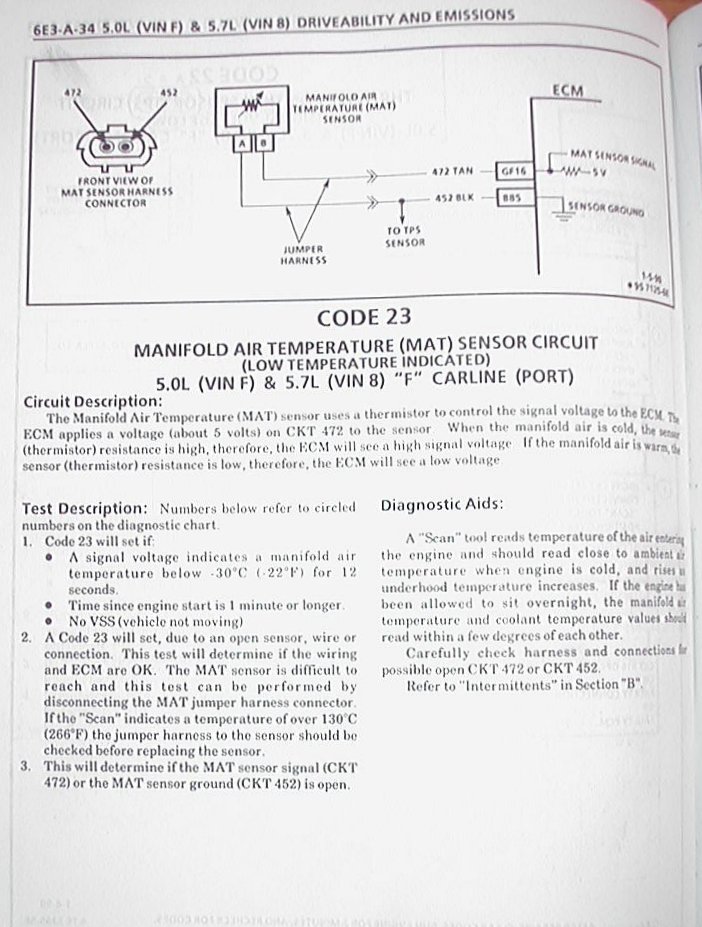
The sensor (not a connector) is a simple resistor that varies by temperature so you should be able to measure that directly with your meter either by voltage while power is on, or by ohms with power off and disconnected from circuit. The instructions posted is doing the same thing through the computer which automatically verifies the wiring at the same time. The �diagnostic aid� in the manual (posted) should help you ohm the sensor if you only have a meter and a temp gun to verify the temperature the sensor is at. You don't want to call the sensor a connector as they are two different things.
*The instructions say that there should be 5volts (ckt 472) where you mention seeing 12volts. That would be a problem that you need to figure out on your end.
*Also check the ecm grounds and any other associated grounds as they can cause all sorts of havoc due to floating voltages.
So from the above info you could try unplugging the connector at the ecm and either using a continuity or ohm setting to check the wiring from the ecm connector to where the sensor connects (best way). If you can hook this up solid with the continuity beeper you could try moving the wiring around to see if it interrupts or not. An alternative would be to bypass it with a wire and see if there is any difference. Ideally a good one from a donor car could be used to plug everything in directly. Ie. Pushing in the barb and swapping the individual wires. Or you may be able to red-neck something in from the back of the connector/s to bypass it. A third way to check it might be with the power on checking for difference in voltage from each end of the wire. It should read close to zero since the wiring has little resistance. Or you could check either end to ground if you suspect the wire is pinched (again power off).
I don't know the location of the wire you're looking for and you'll need the correct pin out diagram for your year and engine etc. Another thing is to make sure the wiring is the same color even though many of the wires in the loom are the same or close to the same color. If your wire at the sensor is say blue and the one at the ecm connector is brown you obviously have the wrong one. Plus when you check the continuity you'll know you have the right wire going in. Again you could use the beeper mode connected to the sensor wire end, and run the other meter lead across the ecm connectors to locate the wire you need. When it beeps you've found your wire. You're obviously going to need to rig up some kind of extension for you meter wires. A long wire with protected alligator clips works good for this.
Hope this helps, I'm sitting up waiting for a few thunderstorms to pass by. lol
Antifreeze contamination should be easy to check by smell and also by removing and checking the ECM for antifreeze residue. The harness may still be wet in places like the connector(even inside) or where wires are close together. Doesn't seem likely but if it is you want to clean and dry it out. Antifreeze is corrosive and enhances conductivity iirc. Would be a mess if it's inside of the ecm connector.
Wiring is sometimes difficult to diagnose for a few reasons. It can open at a connector/wire joint(hidden), anywhere internally inside of the covering, interrupted by corrosion on connector surfaces(easy to check), being wet, or it can be pinched and short out against ground and/or other wiring. When any of this happens it can create an intermittent failure that can vary when the wiring is physically moved, temperature, humidity, and other random factors. Not as likely but that depends on the condition of the wiring and connector interface/s.
Either of the above situations need to be checked and resolved before plugging in another ECM or you may damage the new one right away. This can also happen if a sensor or some other outside connection damaged the ECM. You really want to try to find a reason for its failure and resolve it before slapping another in its place.
I would try to get a �new� ECM and whatever wiring and connectors you need at a junk yard, or from a car being parted out locally, say on Craigslist or something. It's not a bad idea to have a spare computer anyways if you can get it cheap enough. Keep in mind to get one from the same year with the same engine/tranny. Others may work if you look up the info and learn what the differences are. If you get something close you may be able to get by cheaper by replacing just the chip (internally).
You should be able to remove individual wires from a GM connector by locating the metal barb and pushing it in while pulling out the wire. This may help you as you read below. You can google to find examples demos etc.
The sensor (not a connector) is a simple resistor that varies by temperature so you should be able to measure that directly with your meter either by voltage while power is on, or by ohms with power off and disconnected from circuit. The instructions posted is doing the same thing through the computer which automatically verifies the wiring at the same time. The �diagnostic aid� in the manual (posted) should help you ohm the sensor if you only have a meter and a temp gun to verify the temperature the sensor is at. You don't want to call the sensor a connector as they are two different things.
*The instructions say that there should be 5volts (ckt 472) where you mention seeing 12volts. That would be a problem that you need to figure out on your end.
*Also check the ecm grounds and any other associated grounds as they can cause all sorts of havoc due to floating voltages.
So from the above info you could try unplugging the connector at the ecm and either using a continuity or ohm setting to check the wiring from the ecm connector to where the sensor connects (best way). If you can hook this up solid with the continuity beeper you could try moving the wiring around to see if it interrupts or not. An alternative would be to bypass it with a wire and see if there is any difference. Ideally a good one from a donor car could be used to plug everything in directly. Ie. Pushing in the barb and swapping the individual wires. Or you may be able to red-neck something in from the back of the connector/s to bypass it. A third way to check it might be with the power on checking for difference in voltage from each end of the wire. It should read close to zero since the wiring has little resistance. Or you could check either end to ground if you suspect the wire is pinched (again power off).
I don't know the location of the wire you're looking for and you'll need the correct pin out diagram for your year and engine etc. Another thing is to make sure the wiring is the same color even though many of the wires in the loom are the same or close to the same color. If your wire at the sensor is say blue and the one at the ecm connector is brown you obviously have the wrong one. Plus when you check the continuity you'll know you have the right wire going in. Again you could use the beeper mode connected to the sensor wire end, and run the other meter lead across the ecm connectors to locate the wire you need. When it beeps you've found your wire. You're obviously going to need to rig up some kind of extension for you meter wires. A long wire with protected alligator clips works good for this.
Hope this helps, I'm sitting up waiting for a few thunderstorms to pass by. lol
Thread Starter
Supreme Member
Joined: Dec 2013
Posts: 1,122
Likes: 0
From: Indiana
Car: 92 Formula WS6, T-top
Engine: 5.7L T.P.I.
Transmission: 700r4
Axle/Gears: Limited slip, 3.23 10 bolt
Re: How do I compete a circuit to test an ECM wire?
It may help, but I'll have to review it. Some of it is over my head. Again, I'm a novice at this. Btw, the YouTube video I found said there was supposed to be 12 volts at the ground, and 5 at the signal wire. The 5 at the signal wire is what I don't have, and according to the video, it means I have a bad ECM. I just wanted to investigate the wiring to make sure there wasnt a problem there. Thx.
Trending Topics
Supreme Member
iTrader: (4)
Joined: Sep 2004
Posts: 2,069
Likes: 4
From: MN
Car: 85 SC, 86 Berlinetta
Engine: V6, V8
Transmission: 700r4, 700r4
Re: How do I compete a circuit to test an ECM wire?
Oh, ok. that makes sense. I don't get 12v at ground though? 5v at the signal wire but where is the negative lead connected to? Post up the vid if you can. I may be back later today but I'll look at it if you do.
Yep, a lot of it is learning hands on vs. reading. I'm far from being a mechanic but was an electronic tech for a few years helping people fix things over the phone at times. It was written in layman�s terms as much as possible. Print it out and keep it around and a lot of it should make more sense if/when you're hands on and might also help as a reference and/or what to look up when the time comes.
Yep, a lot of it is learning hands on vs. reading. I'm far from being a mechanic but was an electronic tech for a few years helping people fix things over the phone at times. It was written in layman�s terms as much as possible. Print it out and keep it around and a lot of it should make more sense if/when you're hands on and might also help as a reference and/or what to look up when the time comes.
Thread Starter
Supreme Member
Joined: Dec 2013
Posts: 1,122
Likes: 0
From: Indiana
Car: 92 Formula WS6, T-top
Engine: 5.7L T.P.I.
Transmission: 700r4
Axle/Gears: Limited slip, 3.23 10 bolt
Re: How do I compete a circuit to test an ECM wire?
.
Last edited by TheExaminer; Jun 19, 2014 at 07:10 PM.
Thread Starter
Supreme Member
Joined: Dec 2013
Posts: 1,122
Likes: 0
From: Indiana
Car: 92 Formula WS6, T-top
Engine: 5.7L T.P.I.
Transmission: 700r4
Axle/Gears: Limited slip, 3.23 10 bolt
Re: How do I compete a circuit to test an ECM wire?
Here's the video. It's very rudimentary. BTW, I forgot to mention this morning--I was in a rush to get to work--when I say "connector" I mean I actually bought a new connector that the sensor plugs into because the retainer clip broke off the old one, and I thought I'd go ahead and replace it while I had it apart. But I'm getting a reading of 0.02-0.08 at the signal wire, and the video says it should be 0.7-5 volts depending on temp. The video described how to connect the multimeter to test the two wires. One time you put black lead on negative, the other time red lead on positive to the battery and the other one to the connector, etc. Youll see what I mean. I tried testing the sensor itself using the ohms feature on my meter. I got mixed results because I wasnt sure which ohm setting to use. I dialed it to 2K and got a reading of 1.700 - 1.900 on the meter. At 20K I get a reading of 2.2. I don't know if that's right because I don't know if I had the right setting. I guess either way that's about the same reading with a different decimal reference. The sensor has been sitting in the back seat of the car all day, it's probably around 100 F or so.
Last edited by TheExaminer; Jun 19, 2014 at 07:16 PM.
Thread Starter
Supreme Member
Joined: Dec 2013
Posts: 1,122
Likes: 0
From: Indiana
Car: 92 Formula WS6, T-top
Engine: 5.7L T.P.I.
Transmission: 700r4
Axle/Gears: Limited slip, 3.23 10 bolt
Re: How do I compete a circuit to test an ECM wire?
I've been thinking about that ohm reading. When I read 2.2 at 20k, is that telling me 2.2 units of 20k? If so that would be 44,000 ohms. If that's true, the sensor is bad because it's giving a reading that shows air temp of -20F (according to the chart above) or so when it was in a hot car and probably around 90F or so. Is that right? Am I interpreting that reading correctly? If that's what it is, it would result in a mixture that is much too rich, which is what I think I have. I get a loping idle with low rpms when I start it up cold, a gas smell from the exhaust, and it runs crappy and gets poor fuel mileage. Someone let me know if I'm on the right track here.
Thread Starter
Supreme Member
Joined: Dec 2013
Posts: 1,122
Likes: 0
From: Indiana
Car: 92 Formula WS6, T-top
Engine: 5.7L T.P.I.
Transmission: 700r4
Axle/Gears: Limited slip, 3.23 10 bolt
Re: How do I compete a circuit to test an ECM wire?
Oh, ok. that makes sense. I don't get 12v at ground though? 5v at the signal wire but where is the negative lead connected to? Post up the vid if you can. I may be back later today but I'll look at it if you do.
Yep, a lot of it is learning hands on vs. reading. I'm far from being a mechanic but was an electronic tech for a few years helping people fix things over the phone at times. It was written in layman�s terms as much as possible. Print it out and keep it around and a lot of it should make more sense if/when you're hands on and might also help as a reference and/or what to look up when the time comes.
Yep, a lot of it is learning hands on vs. reading. I'm far from being a mechanic but was an electronic tech for a few years helping people fix things over the phone at times. It was written in layman�s terms as much as possible. Print it out and keep it around and a lot of it should make more sense if/when you're hands on and might also help as a reference and/or what to look up when the time comes.
Supreme Member
iTrader: (4)
Joined: Sep 2004
Posts: 2,069
Likes: 4
From: MN
Car: 85 SC, 86 Berlinetta
Engine: V6, V8
Transmission: 700r4, 700r4
Re: How do I compete a circuit to test an ECM wire?
You're welcome, I was hoping it would be something that would help you see a bigger picture of sorts.
I usually use an auto-range meter so I don't have to mess with the settings. With yours you need to have an idea of what resistance you're going to measure and set it accordingly. If you're too far out of range the meter won't give you the correct reading. Anyways, from the �diagnostic Aid� box it says to expect 1,800 ohm at 100� F. So you would want the meter in the 2,000 ohm range to measure it and it looks like what you measured is correct.
As far as the other, it could be anything from the computer, a bad o2 sensor, or a vacuum leak. Without the correct temperature signal, the ecm probably won't go into what is called "closed loop" where it would make adjustments. Also, if it isn't up to temp (or sees that it is) it could be running rich as it's supposed to while warming up. However, it wouldn't be from seeing the temp at -20� and adding more. From what I recall it would need a trigger temp from the engine being warmed up to switch over to closed loop. With the ecm suspect I wouldn't worry about that right now.
Ok, from the video the 12 volt test is simply checking for ground. You could also check the ground wire to ground (Ie. alternator bracket etc.) using the ohm or continuity checker. It's two different ways of checking the same thing. I might stick with the method described though.
I agree that the 5v check would be for the computer(ecm) output (the sensor needs 5 volts to work), but as you were saying I would double check the voltage at the computer connector to rule out the wiring in-between. I would also check the ground for the computer itself through the connector using a pin out chart for reference for it's ground wires.
You were saying that the mechanic noticed that the transmission was getting the wrong signals as well so that might also be an indicator that the ecm needs to be checked out. Did you try unplugging the ecm connector and look around for antifreeze? Remember to disconnect the battery when you unplug the ecm.
Thread Starter
Supreme Member
Joined: Dec 2013
Posts: 1,122
Likes: 0
From: Indiana
Car: 92 Formula WS6, T-top
Engine: 5.7L T.P.I.
Transmission: 700r4
Axle/Gears: Limited slip, 3.23 10 bolt
Re: How do I compete a circuit to test an ECM wire?
You're welcome, I was hoping it would be something that would help you see a bigger picture of sorts.
I usually use an auto-range meter so I don't have to mess with the settings. With yours you need to have an idea of what resistance you're going to measure and set it accordingly. If you're too far out of range the meter won't give you the correct reading. Anyways, from the “diagnostic Aid” box it says to expect 1,800 ohm at 100� F. So you would want the meter in the 2,000 ohm range to measure it and it looks like what you measured is correct.
As far as the other, it could be anything from the computer, a bad o2 sensor, or a vacuum leak. Without the correct temperature signal, the ecm probably won't go into what is called "closed loop" where it would make adjustments. Also, if it isn't up to temp (or sees that it is) it could be running rich as it's supposed to while warming up. However, it wouldn't be from seeing the temp at -20� and adding more. From what I recall it would need a trigger temp from the engine being warmed up to switch over to closed loop. With the ecm suspect I wouldn't worry about that right now.
Ok, from the video the 12 volt test is simply checking for ground. You could also check the ground wire to ground (Ie. alternator bracket etc.) using the ohm or continuity checker. It's two different ways of checking the same thing. I might stick with the method described though.
I agree that the 5v check would be for the computer(ecm) output (the sensor needs 5 volts to work), but as you were saying I would double check the voltage at the computer connector to rule out the wiring in-between. I would also check the ground for the computer itself through the connector using a pin out chart for reference for it's ground wires.
You were saying that the mechanic noticed that the transmission was getting the wrong signals as well so that might also be an indicator that the ecm needs to be checked out. Did you try unplugging the ecm connector and look around for antifreeze? Remember to disconnect the battery when you unplug the ecm.
What it does is idle at such a low rpm when I start it that it will die if I don't give it gas. The exhaust has a rich smell to it also. When you start driving it will act a little better, but it still doesn't sound quite right, it's hard to describe. You can tell by the way it sounds that the mixture is off. Once it's warmed up, the low idle at startup goes away, but there's something still off about it under driving conditions, and it uses too much gas. Sounds like the problem is that low voltage reading at the IAT connector. So if you limit it to that, it's either the wire or the ECM, correct? It did this a few weeks back, then stopped doing it for a couple weeks, then started again. Sounds like an electrical issue to me, and I hate wiring issues.
I've looked at the ECM, haven't seen any obvious signs of coolant, but I plan to look closer when I run some tests. I know the first time I looked at it, it was out of it's cradle just hanging there, so I put it back. It may have been hanging down lower when the heater core failed. Thx again....
Last edited by TheExaminer; Jun 20, 2014 at 05:22 PM.
Supreme Member
iTrader: (4)
Joined: Sep 2004
Posts: 2,069
Likes: 4
From: MN
Car: 85 SC, 86 Berlinetta
Engine: V6, V8
Transmission: 700r4, 700r4
Re: How do I compete a circuit to test an ECM wire?
Yes, I suppose it can get confusing when it's near the different settings. I only have one meter like that and don't use it too often.
As I was saying I'm not a mechanic so I'm not sure. It may not be as simple as the one sensor especially if the mechanic mentioned the transmission issue. I was mostly trying to help you understand how to check the things mentioned in the manual and also to look around for signs of antifreeze to determine if that contributed to the failure.
If it does go away again, try to get a reading of the 5v lead on the sensor end to see if it has changed.
Otherwise you can check the voltage at the ecm output to rule out a wiring issue.
If you open up the ecm check to see if the solder is grayish or shiny. Over the years cold solder joints can cause problems on the circuit board as well.
Thread Starter
Supreme Member
Joined: Dec 2013
Posts: 1,122
Likes: 0
From: Indiana
Car: 92 Formula WS6, T-top
Engine: 5.7L T.P.I.
Transmission: 700r4
Axle/Gears: Limited slip, 3.23 10 bolt
Re: How do I compete a circuit to test an ECM wire?
Just about every diagram I've checked so far says c12 is the IAT input. I'll try to check it later today and go from there. I really hope it's the ECM, because I don't want to mess with a wiring harness problem. That's the short definition of nightmare.
Joined: Aug 1999
Posts: 5,261
Likes: 461
From: RI
Car: 1984 Camaro Berlinetta
Engine: LT1
Transmission: T56 6-speed
Axle/Gears: 4.11 LS1 Rear End
Re: How do I compete a circuit to test an ECM wire?
All I want to know is if the wire is in tact between c12 (Haynes manual) and the connector. But your page here says it's at GF16, so where is it?
The flowchart I posted for you is directly from the 91 shop manul specifically for Speed Density Tuned Port Injection.
You're refering back to "C12",...... that information is from a MAF ECM wiring diagram.
Use the FLowcharts I posted for your diagnostics.
Thread Starter
Supreme Member
Joined: Dec 2013
Posts: 1,122
Likes: 0
From: Indiana
Car: 92 Formula WS6, T-top
Engine: 5.7L T.P.I.
Transmission: 700r4
Axle/Gears: Limited slip, 3.23 10 bolt
Re: How do I compete a circuit to test an ECM wire?
I don't have a scan tool, and have never used one. I could rent one form Autozone and learn to use it, and it may come to that. Second, I know I'm an ignoramus about all this, but the flow chart that you posted doesn't seem to resolve my problem. I already know the sensor is probably not bad, and if I follow the flow chart to the other side, both options tell me "faulty connection or faulty ECM". Seeing as I already know that it has to be one of those two things and I've not even done the flow chart, how does that help me? I already know that it has to either be the wire between the connector and the ECM, or the ECM itself because I have 0.08 volts at the signal wire. I've had guys send me diagnostic flow charts about issues several times on here, and while I do appreciate the information and help, they don't help me as much as I'd like. All I want to know is which pin is the input for the IAT sensor. If it's not c12, it has to be another one. I already know I can check continuity when I know which pin to use.
Supreme Member
iTrader: (4)
Joined: Sep 2004
Posts: 2,069
Likes: 4
From: MN
Car: 85 SC, 86 Berlinetta
Engine: V6, V8
Transmission: 700r4, 700r4
Re: How do I compete a circuit to test an ECM wire?
there are more diagrams at Austin Thirdgen.
http://www.austinthirdgen.org/?pid=19
C12 is on this one (right hand side), a tan wire that goes to the AIT sensor:
http://austinthirdgen.org/mkportal/m...ine_wiring.gif
Even then you can still trace the wire back as I described before. Knowing the color should help reduce the wires to check. It would hurt to go from pin to pin checking voltages as well.
I'm not sure if this is the right one but found it by googling, it shows the location of C12 (note center image where it shows where c1 begins and ends at c16):
http://www.eecis.udel.edu/~davis/z28...165v8tpi-6.jpg
Views better here:
https://www.thirdgen.org/forums/tpi/...-diagrams.html
Check the voltage at the ecm. And also check the wiring continuity and also to ground.
Thread Starter
Supreme Member
Joined: Dec 2013
Posts: 1,122
Likes: 0
From: Indiana
Car: 92 Formula WS6, T-top
Engine: 5.7L T.P.I.
Transmission: 700r4
Axle/Gears: Limited slip, 3.23 10 bolt
Re: How do I compete a circuit to test an ECM wire?
there are more diagrams at Austin Thirdgen.
http://www.austinthirdgen.org/?pid=19
C12 is on this one (right hand side), a tan wire that goes to the AIT sensor:
http://austinthirdgen.org/mkportal/m...ine_wiring.gif
Even then you can still trace the wire back as I described before. Knowing the color should help reduce the wires to check. It would hurt to go from pin to pin checking voltages as well.
I'm not sure if this is the right one but found it by googling, it shows the location of C12 (note center image where it shows where c1 begins and ends at c16):
http://www.eecis.udel.edu/~davis/z28...165v8tpi-6.jpg
Views better here:
https://www.thirdgen.org/forums/tpi/...-diagrams.html
Check the voltage at the ecm. And also check the wiring continuity and also to ground.
http://www.austinthirdgen.org/?pid=19
C12 is on this one (right hand side), a tan wire that goes to the AIT sensor:
http://austinthirdgen.org/mkportal/m...ine_wiring.gif
Even then you can still trace the wire back as I described before. Knowing the color should help reduce the wires to check. It would hurt to go from pin to pin checking voltages as well.
I'm not sure if this is the right one but found it by googling, it shows the location of C12 (note center image where it shows where c1 begins and ends at c16):
http://www.eecis.udel.edu/~davis/z28...165v8tpi-6.jpg
Views better here:
https://www.thirdgen.org/forums/tpi/...-diagrams.html
Check the voltage at the ecm. And also check the wiring continuity and also to ground.
Joined: Aug 1999
Posts: 5,261
Likes: 461
From: RI
Car: 1984 Camaro Berlinetta
Engine: LT1
Transmission: T56 6-speed
Axle/Gears: 4.11 LS1 Rear End
Re: How do I compete a circuit to test an ECM wire?
I just saw the diagram in this link; It's from a 1986 Shop manual,.... = MAF.
https://www.thirdgen.org/forums/tpi/...-diagrams.html
This one is for a 92 Throttle Body:
http://austinthirdgen.org/mkportal/m...ine_wiring.gif
Your 91 is You've got Speed Desnsity and the ECM connector doesn't have a "C12".
The flowcharts I posted were from a 91 Shop manual..... It might not help because you don't have a scan tool,but it deos tell you that - in your car the MAT sensor circuit is # 472, TAN wire @ GF16.
Now you know where to check for continuity.
https://www.thirdgen.org/forums/tpi/...-diagrams.html
This one is for a 92 Throttle Body:
http://austinthirdgen.org/mkportal/m...ine_wiring.gif
Your 91 is You've got Speed Desnsity and the ECM connector doesn't have a "C12".
All I want to know is which pin is the input for the IAT sensor. If it's not c12,I already know I can check continuity when I know which pin to use.
Now you know where to check for continuity.
Thread Starter
Supreme Member
Joined: Dec 2013
Posts: 1,122
Likes: 0
From: Indiana
Car: 92 Formula WS6, T-top
Engine: 5.7L T.P.I.
Transmission: 700r4
Axle/Gears: Limited slip, 3.23 10 bolt
Re: How do I compete a circuit to test an ECM wire?
Scorp, some of those diagrams are for the 5.0, mine is a 5.7--any problem there? Wait, nevermind. No dif. Haynes manual has them both on the same page.....
Last edited by TheExaminer; Jun 21, 2014 at 04:36 PM.
Thread Starter
Supreme Member
Joined: Dec 2013
Posts: 1,122
Likes: 0
From: Indiana
Car: 92 Formula WS6, T-top
Engine: 5.7L T.P.I.
Transmission: 700r4
Axle/Gears: Limited slip, 3.23 10 bolt
Re: How do I compete a circuit to test an ECM wire?
I just saw the diagram in this link; It's from a 1986 Shop manual,.... = MAF.
https://www.thirdgen.org/forums/tpi/...-diagrams.html
This one is for a 92 Throttle Body:
http://austinthirdgen.org/mkportal/m...ine_wiring.gif
Your 91 is You've got Speed Desnsity and the ECM connector doesn't have a "C12".
The flowcharts I posted were from a 91 Shop manual..... It might not help because you don't have a scan tool,but it deos tell you that - in your car the MAT sensor circuit is # 472, TAN wire @ GF16.
Now you know where to check for continuity.
https://www.thirdgen.org/forums/tpi/...-diagrams.html
This one is for a 92 Throttle Body:
http://austinthirdgen.org/mkportal/m...ine_wiring.gif
Your 91 is You've got Speed Desnsity and the ECM connector doesn't have a "C12".
The flowcharts I posted were from a 91 Shop manual..... It might not help because you don't have a scan tool,but it deos tell you that - in your car the MAT sensor circuit is # 472, TAN wire @ GF16.
Now you know where to check for continuity.

Thread Starter
Supreme Member
Joined: Dec 2013
Posts: 1,122
Likes: 0
From: Indiana
Car: 92 Formula WS6, T-top
Engine: 5.7L T.P.I.
Transmission: 700r4
Axle/Gears: Limited slip, 3.23 10 bolt
Re: How do I compete a circuit to test an ECM wire?
BTW John, which shop manual are you using, and where can I get it? And I don't know if this matters, but my car is a 92 not a 91.
Last edited by TheExaminer; Jun 21, 2014 at 06:17 PM.
Thread Starter
Supreme Member
Joined: Dec 2013
Posts: 1,122
Likes: 0
From: Indiana
Car: 92 Formula WS6, T-top
Engine: 5.7L T.P.I.
Transmission: 700r4
Axle/Gears: Limited slip, 3.23 10 bolt
Re: How do I compete a circuit to test an ECM wire?
Just pulled the comp. Dont see any evidence at all of coolant damage or corrosion. Pins all look clean. This comp is a reman though, says so on the cover, so it's not original. The only suspect thing I saw was the cts input wire has a little damage, and was taped over. The wire is not broken, but a little snip of the insulation was missing, showing the wire beneath--hence the tape. I even pulled part of the cover off the comp and pulled what I think is the chip? It's in a little plastic cradle with two push clips? Pulled it and it looks clean. I also found c12. It's a tan wire with a black stripe, and that bugs me just a little because the manual says only tan, no black stripe. But I've triple checked it, c12is tan with a black stripe. When I find a piece of wire long enough, I'll do a continuity check. BTW, several of you have mentioned testing the voltage at the computer. How do I do that? Ground one side of the meter against the door jamb or something and tap each wire terminal at the back side of the clip with it plugged into the the comp? Don't want to short something out, I'll wait for a reply before I attempt.
Last edited by TheExaminer; Jun 21, 2014 at 08:07 PM.
Thread Starter
Supreme Member
Joined: Dec 2013
Posts: 1,122
Likes: 0
From: Indiana
Car: 92 Formula WS6, T-top
Engine: 5.7L T.P.I.
Transmission: 700r4
Axle/Gears: Limited slip, 3.23 10 bolt
Re: How do I compete a circuit to test an ECM wire?
Idk, something isn't right. The more wires I check, the more I find that don't match the Haynes. What is GF16? All I have is a,b,c, and d. The only tan wire I have at any 16 is D16. Ironically, it exactly matches the signal wire coming out of the IAT connector. One layout I saw on this very site seemed to say gf16 and c12 were the same.
https://www.thirdgen.org/forums/show...=216453&page=2
Update.... Now figure this out. I have two 32 pin connectors and one 24. The 24 is labeled A and B, and two 32's are both labled C and D and numbered 1-16! So I have TWO C12's, one is tan with a black stripe, and the other is green! Neither is plain tan, and I have no E or F in this whole thing, and certainly have no G.
Last edited by TheExaminer; Jun 21, 2014 at 07:00 PM.
Joined: Aug 1999
Posts: 5,261
Likes: 461
From: RI
Car: 1984 Camaro Berlinetta
Engine: LT1
Transmission: T56 6-speed
Axle/Gears: 4.11 LS1 Rear End
Re: How do I compete a circuit to test an ECM wire?
GF16 = Last pin on the toip row of the green connector.
G = GREEN connector
F = ( top ) ROW
16 = PIN location.
91 amd 92 Speed Density are the same.
G = GREEN connector
F = ( top ) ROW
16 = PIN location.
91 amd 92 Speed Density are the same.
Thread Starter
Supreme Member
Joined: Dec 2013
Posts: 1,122
Likes: 0
From: Indiana
Car: 92 Formula WS6, T-top
Engine: 5.7L T.P.I.
Transmission: 700r4
Axle/Gears: Limited slip, 3.23 10 bolt
Re: How do I compete a circuit to test an ECM wire?
So it's in engineer code? Brilliant. LOL....Meanwhile, to make sure I understand.... GF16 is actually in "D16" slot on the green connector then? Because the wire right above it in "C16" (GE16?) is yellow. The one that I said earlier that matched the signal wire at the IAT is the one that I said I found at D16. But technically, it's on the bottom--that is if you turn the connector around and read the little numbers on the plug face. The row above the numbers has a yellow wire at C16, and below the numbers it is our solid tan friend at D16. So how do the engineers define "top"? You sure E isn't top and F bottom? Everything would line up then and we'd have cuffs on our suspect...... I swear I'm not an idiot--I'm even a college grad--but some of the things I see in automotive engineering make me scratch my head. Thanks for your patience. Now that you've given me this "Rosetta Stone" key, I see what they did--BA, BB, BC, BD, GE, GF, etc. so each individual wire has an address, and you avoid the confusion I was running into earlier this evening. If there's something I'm overlooking, please let me know. 
Last edited by TheExaminer; Jun 21, 2014 at 09:11 PM.
Supreme Member
iTrader: (4)
Joined: Sep 2004
Posts: 2,069
Likes: 4
From: MN
Car: 85 SC, 86 Berlinetta
Engine: V6, V8
Transmission: 700r4, 700r4
Re: How do I compete a circuit to test an ECM wire?
Just pulled the comp. Dont see any evidence at all of coolant damage or corrosion. Pins all look clean. This comp is a reman though, says so on the cover, so it's not original. The only suspect thing I saw was the cts input wire has a little damage, and was taped over. The wire is not broken, but a little snip of the insulation was missing, showing the wire beneath--hence the tape. I even pulled part of the cover off the comp and pulled what I think is the chip? It's in a little plastic cradle with two push clips? Pulled it and it looks clean. I also found c12. It's a tan wire with a black stripe, and that bugs me just a little because the manual says only tan, no black stripe. But I've triple checked it, c12is tan with a black stripe. When I find a piece of wire long enough, I'll do a continuity check.
BTW, several of you have mentioned testing the voltage at the computer. How do I do that? Ground one side of the meter against the door jamb or something and tap each wire terminal at the back side of the clip with it plugged into the the comp? Don't want to short something out, I'll wait for a reply before I attempt.
BTW, several of you have mentioned testing the voltage at the computer. How do I do that? Ground one side of the meter against the door jamb or something and tap each wire terminal at the back side of the clip with it plugged into the the comp? Don't want to short something out, I'll wait for a reply before I attempt.
Measuring the voltage won't ground it out because the meter has a buffer to prevent that, even then in this case it would pull down the signal in the same way that the sensor does.
If the voltage is the same at both the ecm and sensor end you can generally assume that the wire is good. Even if you do a continuity test on the wire, you also want to check it in reference to ground as well since it is suspect. Might be overkill but if you're checking it anyways.
Continuity is done with power off as are resistance checks.
How did the solder joints look when you had it apart? Is it possible to post an image of the circuit board? A reman could mean it had problems before. I would try to pick another ecm up if you can find one cheap.
I wouldn't worry so much about the black stripe on the wire, you know what color the wire is on the sensor end. For some reason I was thinking it was tan & black as well but don't know where I saw that. Try to get a feel for the purpose of what you're doing vs. what is technically in the manual and or diagrams that way you become more self sufficient.
Follow along with John on the diagrams and wiring. I feel he has more experience with that than I do, and it's only going to get confusing with both of us posting diagrams etc.
Thread Starter
Supreme Member
Joined: Dec 2013
Posts: 1,122
Likes: 0
From: Indiana
Car: 92 Formula WS6, T-top
Engine: 5.7L T.P.I.
Transmission: 700r4
Axle/Gears: Limited slip, 3.23 10 bolt
Re: How do I compete a circuit to test an ECM wire?
Yeah, looks like John was right about the c12 thing. My trouble was I didn't understand the wire label system,but now it makes sense. GF16 is a tan wire, right where it's supposed to be. Comp looks solid, maybe you can spot something I missed? Of course, that doesn't mean it's not bad. Who knows what's in a comp's brain....BTW, is that the "chip" I see guys talking about there in the blue clip? One guy on here offered to sell me a new chip that ignored code 32's for $50. If that's all it is, it'd be easy to plug a new one in.
Thread Starter
Supreme Member
Joined: Dec 2013
Posts: 1,122
Likes: 0
From: Indiana
Car: 92 Formula WS6, T-top
Engine: 5.7L T.P.I.
Transmission: 700r4
Axle/Gears: Limited slip, 3.23 10 bolt
Re: How do I compete a circuit to test an ECM wire?
Now I do see THIS....See that "fuzz" looking stuff on the connections? I thought it was just dust at first. But it's in the area behind where the green connector plugs in. Don't know if this is anything or not, I was able to blow most of it out.
Thread Starter
Supreme Member
Joined: Dec 2013
Posts: 1,122
Likes: 0
From: Indiana
Car: 92 Formula WS6, T-top
Engine: 5.7L T.P.I.
Transmission: 700r4
Axle/Gears: Limited slip, 3.23 10 bolt
Re: How do I compete a circuit to test an ECM wire?
Just one more question....I can rig an extension wire to do the ECM test the same as I did at the sensor connector, not a huge issue. But you said to also test in reference to ground at the ECM, is that also as described in the video? That was where I got my 12 volts at the sensor ground wire like it said I was supposed to, is that what you're talking about? I connected one lead to the battery and the other to the sensor connector ground wire, is that safe for the ECM? Thx for all your help, I learn in leaps and bounds on this site.....
Member


Joined: Sep 2005
Posts: 402
Likes: 10
From: Yorktown, VA
Car: 1989 IROC-Z
Engine: L98
Transmission: 700R4
Axle/Gears: 4th gen rear with 3.42
Re: How do I compete a circuit to test an ECM wire?
**deleted**
Last edited by spurgeon76; Jun 21, 2014 at 10:03 PM.
Member
Joined: Sep 2005
Posts: 402
Likes: 10
From: Yorktown, VA
Car: 1989 IROC-Z
Engine: L98
Transmission: 700R4
Axle/Gears: 4th gen rear with 3.42
Re: How do I compete a circuit to test an ECM wire?
If you want to check for continuity. Ground one end of the wire you want to check to a chassis ground (bare metal) then hook the red lead to the other end of the wire and the black lead to another chassis ground. If the wire is good you will have a complete circuit.
Thread Starter
Supreme Member
Joined: Dec 2013
Posts: 1,122
Likes: 0
From: Indiana
Car: 92 Formula WS6, T-top
Engine: 5.7L T.P.I.
Transmission: 700r4
Axle/Gears: Limited slip, 3.23 10 bolt
Re: How do I compete a circuit to test an ECM wire?
Ah yes, I see. So you don't have to actually run a long wire between the two if you don't want to, the chassis itself becomes the connection. That makes sense.
Supreme Member
iTrader: (4)
Joined: Sep 2004
Posts: 2,069
Likes: 4
From: MN
Car: 85 SC, 86 Berlinetta
Engine: V6, V8
Transmission: 700r4, 700r4
Re: How do I compete a circuit to test an ECM wire?
Well, I do see residue from a liquid on the larger square chip on the right hand side, but that may be from a cleaning solution if solder work was done on it. The image is a little blurry, but when I zoom up it looks like there is dust or some kind of brownish debris below the chips with blue cover (rh side)? I'm looking at the open area where a chip would go as well as continuing to the bottom.
I wouldn't so anything with it until you get another ecm that will keep the car running unless you're ok with parking it for a while.
Yes, the chips can be reprogrammed and you can swap between them. However we pretty much know that the sensor is good and you'll know on the wiring soon. So it wouldn't make any sense to bypass it. Remember again that there was mention of the transmission communication so that hasn't been resolved either.
This may help you identify what ecms you can use. The chip may have to be changed with some of them for your application.
http://www.iroczone.com/2009/10/ecmm...oss-reference/
Notice that the part number is the same between different engines.
Year(s), Cylinders, Engine – Ltr (C.I.-Eng Code), ECM Part No.
1992-90 6 3.1 Ltr. (189-T) 1227730
1992-90 8 5.0 Ltr. (305-F) 1227730
1992-90 8 5.7 Ltr. (350-8) 1227730
1992-90 6 3.1 Ltr. (189-T) 1227730
1992-90 8 5.0 Ltr. (305-F) 1227730
1992-90 8 5.7 Ltr. (350-8) 1227730
Joined: Aug 1999
Posts: 5,261
Likes: 461
From: RI
Car: 1984 Camaro Berlinetta
Engine: LT1
Transmission: T56 6-speed
Axle/Gears: 4.11 LS1 Rear End
Re: How do I compete a circuit to test an ECM wire?
Sounds like the problem is that low voltage reading at the IAT connector. So if you limit it to that, it's either the wire or the ECM, correct?
IMO; I'd fix whatever is causing the code. Once I knew the problem was correctly resoved and was confident in the way it drove and felt again; then I'd consider a custom chip ( for several other additional modifications !! )
Thread Starter
Supreme Member
Joined: Dec 2013
Posts: 1,122
Likes: 0
From: Indiana
Car: 92 Formula WS6, T-top
Engine: 5.7L T.P.I.
Transmission: 700r4
Axle/Gears: Limited slip, 3.23 10 bolt
Re: How do I compete a circuit to test an ECM wire?
Ok. Well I just meant a chip to bypass the nebulous code 32 egr issue I keep having. But after I get this fixed it may resolve itself, plus I'm going to do a continuity test on the egr solenoid wiring as well now that I know how to do it. Ignoring a code 23 could be dangerous, I wouldn't want to bypass that one. As far as the tranny goes, it's not bad for 155K, but I notice that it doesn't hit as well as it should when you take off. It kind of double clutches just a little before taking off like it should, could be something that will need work later, or it could be the computer. This makes for take offs that are a little less cool than I remember my old 91 having. There weren't many cars on the road back then (95-99) that could jump a green light quite like that one could. If it wasn't a Porsche or a Corvette, I'd probably toast it. This car doesn't kick quite as high, and part of it could be this mixture/computer issue I have.
Thread Starter
Supreme Member
Joined: Dec 2013
Posts: 1,122
Likes: 0
From: Indiana
Car: 92 Formula WS6, T-top
Engine: 5.7L T.P.I.
Transmission: 700r4
Axle/Gears: Limited slip, 3.23 10 bolt
Re: How do I compete a circuit to test an ECM wire?
It's been a year or 2 since I've touched a full TPI set-up,...... but isn't there a short 2 wire harness with a connector at each end used to connect the sensor and the engine harness ?? ( or was that little factory 'jumper' harness for the EGR relay ?? ) That would be one more possible place for a bad connection between plugs.
IMO; I'd fix whatever is causing the code. Once I knew the problem was correctly resoved and was confident in the way it drove and felt again; then I'd consider a custom chip ( for several other additional modifications !! )
IMO; I'd fix whatever is causing the code. Once I knew the problem was correctly resoved and was confident in the way it drove and felt again; then I'd consider a custom chip ( for several other additional modifications !! )
Thread Starter
Supreme Member
Joined: Dec 2013
Posts: 1,122
Likes: 0
From: Indiana
Car: 92 Formula WS6, T-top
Engine: 5.7L T.P.I.
Transmission: 700r4
Axle/Gears: Limited slip, 3.23 10 bolt
Re: How do I compete a circuit to test an ECM wire?
Well, I do see residue from a liquid on the larger square chip on the right hand side, but that may be from a cleaning solution if solder work was done on it. The image is a little blurry, but when I zoom up it looks like there is dust or some kind of brownish debris below the chips with blue cover (rh side)? I'm looking at the open area where a chip would go as well as continuing to the bottom.
I wouldn't so anything with it until you get another ecm that will keep the car running unless you're ok with parking it for a while.
Yes, the chips can be reprogrammed and you can swap between them. However we pretty much know that the sensor is good and you'll know on the wiring soon. So it wouldn't make any sense to bypass it. Remember again that there was mention of the transmission communication so that hasn't been resolved either.
This may help you identify what ecms you can use. The chip may have to be changed with some of them for your application.
http://www.iroczone.com/2009/10/ecmm...oss-reference/
Notice that the part number is the same between different engines.
I wouldn't so anything with it until you get another ecm that will keep the car running unless you're ok with parking it for a while.
Yes, the chips can be reprogrammed and you can swap between them. However we pretty much know that the sensor is good and you'll know on the wiring soon. So it wouldn't make any sense to bypass it. Remember again that there was mention of the transmission communication so that hasn't been resolved either.
This may help you identify what ecms you can use. The chip may have to be changed with some of them for your application.
http://www.iroczone.com/2009/10/ecmm...oss-reference/
Notice that the part number is the same between different engines.
Thread Starter
Supreme Member
Joined: Dec 2013
Posts: 1,122
Likes: 0
From: Indiana
Car: 92 Formula WS6, T-top
Engine: 5.7L T.P.I.
Transmission: 700r4
Axle/Gears: Limited slip, 3.23 10 bolt
Re: How do I compete a circuit to test an ECM wire?
Just did a continuity test, and one more mystery. The battery is disconnected, so I'm only testing the continuity of the solid brown IAT input wire. First, I didn't get a signal of any kind out of the old connector, so apparently it was bad. That's the good news, because I put the new connector on and got a signal at the brown wire. The mystery is, I got a good strong continuity signal when I connected the brown wire to the IAT connector, but only when I put it on what the diagnostic (pictured above) showed as ckt 452, which is ground, not the 472 signal ckt. See what I'm saying? Based on the front view of the connector, it's shape dictates that the left side should be signal ckt 472, but I only get a continuity signal at the brown IAT wire when I plug into the RIGHT side, which the diagram says is ground! But yet the continuity signal is still at the brown wire! Does this even matter as long as the circuit is complete?
Last edited by TheExaminer; Jun 22, 2014 at 09:17 PM.
Thread Starter
Supreme Member
Joined: Dec 2013
Posts: 1,122
Likes: 0
From: Indiana
Car: 92 Formula WS6, T-top
Engine: 5.7L T.P.I.
Transmission: 700r4
Axle/Gears: Limited slip, 3.23 10 bolt
Re: How do I compete a circuit to test an ECM wire?
I've been double checking, and I think that plug illustration is wrong. The brown signal wire is connected to the right side of the connector, not the left--at least on my car. Unless that visual is intended to show the plug from behind, which wouldn't make any sense. But anyway, yeah, it's the right side. You can follow that brown wire right up out of the harness, it comes up on the right, and connects to the right side of the connector, and on up to the plug. If so, my wire is in great shape because I got a very strong signal. Even jiggled the wires around, and it never faltered. Someone slap me with something if I'm wrong.
Last edited by TheExaminer; Jun 22, 2014 at 09:21 PM.

Thread
Thread Starter
Forum
Replies
Last Post
db057
TBI
10
Aug 11, 2015 10:11 PM

