When you click on links to various merchants on this site and make a purchase, this can result in this site earning a commission. Affiliate programs and affiliations include, but are not limited to, the eBay Partner Network.
Upgrading to LT1 Fan from a single stock fan in an '86 Iroc. Also have a couple of different things needing ignition On power. After combing through a lot of threads and talking to several members I've settled on the following diagram.
I'm figuring the wires coming off the positive post should be 12 awg. Anything under 20A will be 18 awg. In theory this would work, but I have some questions that need to be answered to verify it will.
1) Will 20A fuses on the power supplying the fans be large enough or do I need to go for 25A or 30A fuses?
2) The fuse on the line that provides trigger power for Relay B--what is the minimum size this can be? I know on the fuse block it's a 20A but it's also interacting with more than just the relay. Can I get away with a 5A or 10A fuse here?
3a) The fuse on the line that provides trigger power for Relay C--what size can this be?
3b) Does the ignition power source on Relay C need to be running to something that draws power or will it just work going straight to ground? Like does it need to be in line with something like the radio to draw power through the relay?
Seems extremely, excessively, needlessly complicated. Maybe it's just because the wiring diagram is a hot mess, but it seems like you're got a ton of redundant wiring.
Pull out any GM wiring diagram, and just look how much 'stuff' the factory powers off a single fuse. Look at, and endeavor to understand, how GM handled power distribution. They wired an entire car with less fuses.
Why in the world would you run 6 power wires off a battery post or terminal block to a bank of fuses and relays when you could use a single wire to a bus or distribution point on the fuse/relay bank? If nothing else you can create a splice, wire in parallel, and accomplish most of that, with a fraction of the wire and clutter you have diagrammed.
Run ONE power wire for your sound system, off of one sufficiently large fuse, to a distribution block with individual fuses and split it off from that point close to the amps. Grab your power for your CD changer there too.
I'ma venture a guess that you can tie the power wire for your heated O2 sensor into virtually any pink wire with a black trace under the hood, and you're not likely to blow a fuse or burn the car down. A little peeking at the GM wiring diagrams and I'm sure you can find something that your car was designed to power, but wasn't equipped with - meaning you can add something else to the circuit without causing problems.
Idk, do it however you like, but I personally would not do it that way.
It's a bit more than necessary, I'll give you that as I'm not an electrician. GM did wire the car with less fuses but they also had a lot of time to design and test the circuits to decide the bare minimum on the fuses and maximum safety of the wiring capacities. The last thing I want to do is overload 30+yo wiring.
As an example, I considered splicing into the current fan trigger power source for the new fan relay trigger. It's a 20A C/H Fan fuse (IGN Hot) on the block which triggers a coolant fan relay with a couple of other things. Hence my question asking how much the fan relay might actually need to trigger. I'm worried that it would overload the wiring. Ideally I would use a plug on the factory IGN bus for the O2 sensor, tap it in the engine bay as the trigger source for the second fan relay.
Six wires off one post is a bunch so here's the reasoning. Both fan obviously need independently fused power. Currently, there are two wires with inline fuses put in by the PO that run across the radiator all the way back to the amps in the trunk. The box I bought has space for 8 fuses in it so I figured I'd wire from there. One work around I'm considering is adding a BAT fuse block under the dash for the amps and CD changer; would cut down on wires running through the firewall. Space is limited there already, and with the IGN fuse block going in I'll have to check again.
As far as the IGN fuse block, I honestly would rather not have it. The auxiliary panel hooked up to the car's main fuse block has a single rail bus for IGN power. The O2 Sensor, Amp remote, and CD changer could all pull off of that; I know it would handle it and be much cleaner wiring. Unfortunately I can't find the PacK-Con II 56 connectors that hook into bus when searching online; the folks I've reached out to either don't have them or haven't bothered to get back to me (local Pick-N-Save is void of 3rd Gens too). The diagram is a result of no results to the ongoing search for those.
You have a lot posted, and admittedly I am feeling too lazy to address everything you have said, maybe later.
But as a suggestion, I buy these now, compact with a lot of circuit capability and the one with the common stud for the fuse side can be "turned on" by wiring one of the relays as the power feed and ignition triggered. This would cut down on a lot of your individual wiring, as show in in your diagram. You would only need one wire from the battery or alternator to the common stud, then your power off the fuse side for each circuit.
I would also consider wiring your fans in series for "low" and parallel for "high" like GM did. I believe they prove to be less of a current spike for the electrical system this way. In series the resistance is high, so there is a lower current draw for the two, then when "high" is commanded they are already spinning and don't spike a high current to get them up to speed. I have both my 92 dual fans wired to ONE 20 amp fuse in my car and I have them wired in parallel, separate high and lows. GM didn't fuse the fan power sources though, they just used fusible links for each fan. If you use a 12 gauge wire you can go to ~25 amp safely, and if you go 10 gauge you can go to about 40 amp.
You can't stack 6 terminals on a single stud because the nut will keep coming loose. It's an inadequate bolted joint with that many stacked ring terminals.
You can replace the mess of power distribution by using a fuse block with a bus bar in it. Check out the offerings from Bussmann and Delphi. Some styles have two bus bars so you can have a set of fuses with constant B+ and a set of fuses with switched B+.
More things in your diagram should be switched power, not constant power.
Fuse C and relay C seem to serve no purpose other than draining the battery dead. You need to be more specific in your diagram what wires are the control side of a relay vs. the power side of a relay.
The stock fuse block already has most the wiring you want. Why not use it??? Seems kind of nutty to rewire half the damn car just to add a fan circuit.
There's a lot more to say about your circuits but I don't think it's necessary to go on about it right now. My suggestion is think it through again, work out a 2nd draft, and then post new ideas for review. It's likely you're going to go 3 or 4 rounds before final draft.
The factory fan fuse will supply plenty to trip a relay. It's 12v switched, so no problem there. Use 10 or 12ga wire from the battery, junction block, or positive post of the starter, to the switched side of the relays, and from the relays to the fans, and from fans to ground. The rest of the relay wiring is fairly insignificant because it's only triggering the coil.
Splice your O2 into any pink and black under the hood. There's probably an emissions part you've deleted you can tap into, or go for the switched power to the coil, really shouldn't matter much.
Run ONE fused power wire from the battery to your stereo amps. If you want to get fancy, buy a distribution block with individual fuses for each device.
Do the same with the remote turn on and ground for your amps, run one wire for the remote from the head unit, or the power antenna relay wiring. Splice it or daisy chain the remote at the amps and cd changer. Can't say I've every thought about fusing a remote turn on. It's honestly not something I"ve ever seen on any amp wiring diagram.
Don't over think it. Wiring is easy, especially when you can just copy GM's circuits.
Thanks for the thoughts on this! I will be redoing the my wiring diagram to reflect some of the information you shared. It was a bit con-fuse-ing (boo...dad jokes). For starters I'll put which wires are on an trigger coils in the relays--you made a great point about that QwkTrip.
Each of the amps need a 30A power feed. I'd like to fuse them using a small bus fuse block under the dash with the CD changer (prevent tearing out half of the interior panels). Would 12 awg from the battery to the fuse bus be too small or does it need to be 10 awg?
Last edited by Chris Knight; Apr 16, 2019 at 04:13 PM.
Learn to love the distribution block. It's an old photo, had to settle for the trendy wire colors of the era. Red is pos, Blue was neg. One 4ga in, three 8ga out.
Do your amps not have built in fuses?
I mean it'd be kinda odd if they didn't. You only need a fuse at the battery so if the constant power cable gets pinched, punctured etc to ground, to prevent a fire. The amps should have their own built in protections... Even the bottom of the barrel cornball Profile amp I had in my first Camaro had a built in power fuse to protect the amp.
It's an Alpine 3552 amp and Alpine 3555 amp; one has a single 30A fuse and the other a dual 20A fuse. As much as I don't want to take apart the interior, I want to do this right the first time. I'll run that 4 awg wire to the trunk, do you remember what kid of distribution block that is? What type of inline fuse holder would be at the battery?
do you remember what kid of distribution block that is? What type of inline fuse holder would be at the battery?
That one in the pic was all Rockford IIRC, I've got one around here somewhere now that's from Stinger, and I think I've got another in the stereo box from Scosche. Should be able to find several variations on the theme at any car stereo shop, assuming they still exist. Best deals are always found second hand. Only part of that stereo that didn't come from friends, trades, or pawn shops was the 2ch Rockford amp, and it was the display model from the stereo shop. LOL
Per life events I had to put this on the back burner for a while. Going to focus on just getting the cooling fans hooked up at the moment. The (1st) diagram on the bottom right shows a node leading on the wiring with "To Generator" and the other to "Hot in Run" fuse. The only brown wire leading off the Generator appears to go to the Ignition Switch on the second diagram. This indicates the brown wire will only get IGN power (Hot in Run). http://austinthirdgen.org/mkportal/m...ine_wiring.gif http://austinthirdgen.org/mkportal/m..._continued.gif
So the first link is to a 1988 5.7L diagram with dual fans. It clearly indicates that the same 20 amp C/H-Fan fuse is used to trigger both relays on a stock dual fan setup. The difference is on a single fan car, the A/C controls the primary fan, so the green/white wire from the AUX fan relay would only be leading to the Coolant Fan Switch (in the block/probe in radiator/etc.). http://austinthirdgen.org/mkportal/m...ine_wiring.gif
My only question now is on the 1988 diagram, it shows one fusible link feeding both fans relays. Would I be able to do this with LT1 fans on a single fan factory harness or would it be too much current? It looks like I could just splice into the same wire the fusible link draws from and add an inline fuse if not.
Last edited by Chris Knight; Aug 2, 2019 at 11:09 AM.
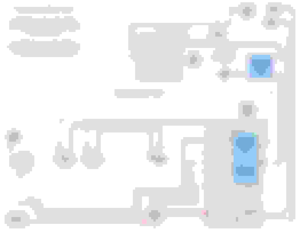
This is what I put together for a fuse block that is IGN Hot only. Inspiration from how a remote wire from a aftermarket head unit can be used to set up a relay for amps. The colors on the wiring diagram correspond to the colors in the car (and hopefully reads better than my first diagram).
The BAT Power and IGN Hot power have been sourced from the C238 Junction Block behind the driver kick panel. Used factory Pack Con II 24 and 27 connectors to hook into the powered rails. Wiring checked with a multi-meter and the block and relay coil only got power once the key was in the ignition on position. Trigger coil measured about 0.15amps while the new fuse block used a whopping 0.62 - 0.76 amps. It was easy to verify as the audio amps only came on when the remote wire got power.
Couple quick questions pertaining to the relay trigger.
What is the most amps a relay trigger handle?
Do I need an actual device on the trigger wire to ensure the relay will work correctly or is hooking it straight to ground OK?
Last edited by Chris Knight; Oct 30, 2019 at 01:36 PM.
Reason: Updated Content and Images