When you click on links to various merchants on this site and make a purchase, this can result in this site earning a commission. Affiliate programs and affiliations include, but are not limited to, the eBay Partner Network.
Hey Guys I'm taking my dash cluster apart finally got it out yesterday.
gauges are working in terms of arm but the dash lights are not working. I have a new battery and the headlights and tails and side markers all work, as well as courtesy lights and dome light if i wiggle it a bit.
The map light by t top is not working, the service engine light does work but the others don't. I turned the headlights on and turned the **** left and right and i have very faint dim lighting on some of the gauges on the left and the hvac area in the console is very dim as well as aftermarket radio. my buddy said the more i unplug and plug back in they might work as its been sitting 3 years. Im going to swap all the gauge bulbs with led but im now wondering if the printed circuit board is bad or if its the dimmer switch entirely with the electrical part, or even the sockets that hold the bulbs . I found that whole replacement for 57 bucks and the circuit board sheet is 99 bucks just wanna know what should i do to address this efficiently without buying stuff i don't need. all fuses look good and aren't cracked as well but i may just replace the fuses and see if it makes a difference. i just wanna get all the bulbs working properly in the dash . circuit board sheet
I just rebuilt my gauge cluster after finding all the correct gauges and what not. That printed circuit board "looks" fine to me. You could use a voltmeter and insure you have continuity to each bulb path and also use it when install the bulbs. I went with non-led bulbs since I am going for a more period correct look. I would also look at the prongs where the circuit board plugs into the dash to make sure, they are clean and line up to the board nicely. All this probably will not solve your overall problem, but if you are there with the cluster pulled out you could replace the dimmer switch? That is super easy with the gauge cluster out. The last recommendation is to check the ground wires under the dash. Take the self-tapping bolt out, clean the metal with a little sandpaper as well as the eyelet connectors. Again, may not solve the problem.
I just rebuilt my gauge cluster after finding all the correct gauges and what not. That printed circuit board "looks" fine to me. You could use a voltmeter and insure you have continuity to each bulb path and also use it when install the bulbs. I went with non-led bulbs since I am going for a more period correct look. I would also look at the prongs where the circuit board plugs into the dash to make sure, they are clean and line up to the board nicely. All this probably will not solve your overall problem, but if you are there with the cluster pulled out you could replace the dimmer switch? That is super easy with the gauge cluster out. The last recommendation is to check the ground wires under the dash. Take the self-tapping bolt out, clean the metal with a little sandpaper as well as the eyelet connectors. Again, may not solve the problem.
Thanks seems like you are basically saying to do everything im considering... When you say ( prongs where the circuit board plugs into the dash) what do you mean when i pulled the gauge cluster out i only see 2 rectangular port looking things about 2 inches wide that are white but nothing is plugged into them. not sure if this is what youre referring to or not and or if this could be causing the issue if somethings missing
"When you say (prongs where the circuit board plugs into the dash) what do you mean when i pulled the gauge cluster out i only see 2 rectangular port looking things about 2 inches wide that are white but nothing is plugged into them"
The gauge cluster plugs into those "ports". That is what make the connection from the harness to the gauges cluster via the printed circuit board. If you look closely at those white "ports" the wires are terminated to silver looking prongs (for lack of a better word). Make sure those are clean. I used a small flat head to gently lift each "prong" up a "tab" in the white "ports" to make sure there was a good contact between the two parts.
I would not spend the money on the printed circuit board IMO.
Needs a bulb most likely. It's powered by the same circuit as the dome light so it's not a fuse and not likely the wiring.
service engine light does work but the others don't
Check the INST LPS fuse. Probably not The Problem butt wouldn't hurt to take a look.
2 rectangular port looking things about 2 inches wide that are white but nothing is plugged into them
Those are the connectors that connect the whole cluster to the rest of the car. The reason nothing is plugged into them is because the cluster is in your hand instead of in the dash. If you LOOK AT where it came from, you'll see the 2 connector halves back in there, just waiting for the cluster to be pressed back on over them.
Most likely, the whole thing isn't grounded properly. The flex PCB carries ground to all the things that need it; gauges, lights, etc. If that connection, either where the connector plugs into it, or the other end of the ground wire where it lands on metal behind the dash, is bad, then all sorts of things won't work. Gauges, high beam indicator, illumination, TS indicators, EVERYTHING that requires ground, will be affected. Note that the SES light would NOT be affected by this: one side of the bulb goes to the pink/blk circuit (ECM 12V), and the other side goes to the lamp driver, therefore the ground on the PCB isn't involved. Some of the other indicators may also work without that ground for the same reason, I just don't remember that much detail about it all. There are several pins on that thing that are ground (i.e. ground is either split up or duplicated before going to each device), at least 3 if memory serves, therefore it would take 3 or more simultaneous failures to disable the whole dash, therefore it is EXTREMELY unlikely to be the fault of the connection between the cluster and the dash. FAR MORE likely to be the wire from the dash connectors to the car's metal chassis. That wire will be black and will have a ring terminal at the chassis end that gets screwed down.
Again, LOOK AT the flex PCB. You'll observe that EVERY ONE of the illumination bulbs has 2 terminals, and that EVERY ONE is connected to the same 2 traces of the PCB. One of those is the power to light the lights; the other is ground. You can tell which is which by LOOKING AT where those traces go: the ground side goes to other things that need to be grounded, such as certain of the gauges, and the other goes to nothing butt other illumination lamps. Easy enough to do the math on which one is which. Follow the ground trace down to the connector; make double damn sure that the copper is clean and bright where the connector plugs into it, and that the mating surface of the connector in the dash is also clean and bright. If necessary, clean them up: use a rag moistened with vinegar to wipe them, followed by another rag moistened with a solution of baking soda in hot water, followed by another rag moistened with clean pure water. Be absolutely certain that no trace of vinegar remains anywhere. I'd only do this if I find corrosion or whatever on the contacts as this is highly unlikely to be The Problem.
The bulb in the 2nd pic looks good to me; at least, I see no breaks in the filament. The others, I can't tell. The illumination bulbs, in the grey housings, are part # 194. Just swap em all out.
I don't see anything wrong with your flex PCB beyond normal old age. Nothing burned up etc. Those don't go bad much except by too aggressive handling (pencil eraser on the contacts for example), wearing through where things connect to it, or burning up at a connection. I'd hold off on spending money on anything other than bulbs, especially since it's so eeeeeeezy and quick to pop the cluster out again if need be.
All of this is extremely simple. It's the simplest part (lights) of the simplest system (electrical) in one of the simplest assemblies made by humans (a car). It's just not that hard.
Last edited by sofakingdom; Nov 6, 2025 at 11:24 AM.
"When you say (prongs where the circuit board plugs into the dash) what do you mean when i pulled the gauge cluster out i only see 2 rectangular port looking things about 2 inches wide that are white but nothing is plugged into them"
The gauge cluster plugs into those "ports". That is what make the connection from the harness to the gauges cluster via the printed circuit board. If you look closely at those white "ports" the wires are terminated to silver looking prongs (for lack of a better word). Make sure those are clean. I used a small flat head to gently lift each "prong" up a "tab" in the white "ports" to make sure there was a good contact between the two parts.
I would not spend the money on the printed circuit board IMO.
Thanks yea after starring at the back of cluster and circuit board i see what you mean with the male plugs going into the female area of the cluster with copper points touching, i ordered new bulbs and sockets for all the bulbs was probably 25 bucks or so. i sprayed eletrical cleaner into the ports with tabs but did not lift any with a flathead like you mentioned. i may disconnect the battery and try that this weekend. ill keep ya posted thanks
helpful info thank you, yea i found one ground under the steering collumn wiped the metal and put a washer between that and the bolt might hve to sand the metal a bit or remove the washer not sure if thats helping or hindering it. i only have found that one ground wire by the steering collumn not another that they say is behind the radio or something
I think the one near the column is the one in question.
I try VERY HARD to avoid messing with connector parts unless it's absolutely unavoidable. The metal they're made out of isn't capable of withstanding bending back and forth too much. More often than not, "tightening" them only shortens their life span; they work GREAT for a little while, butt then fail again and need "bent" back some more, and then they fail again in about half the time, and then in about half that time the next time, and so on. Pencil-erasing them has a similar effect: whatever plating or coating they might have had, gets stripped off, and you're left with base metal that corrodes 5 times as fast as the original. All of it is stepping off the path to chase after the shiny things.
Speaking strictly as someone that has worked as an electrical and electronic engineer for the best part of 50 years now. Test eqpt, telephone systems, broadcast stations, live & recording studio audio, most recently hospital operating room power systems. So, not like I've ever seen any connectors or anything.
I think the one near the column is the one in question.
I try VERY HARD to avoid messing with connector parts unless it's absolutely unavoidable. The metal they're made out of isn't capable of withstanding bending back and forth too much. More often than not, "tightening" them only shortens their life span; they work GREAT for a little while, butt then fail again and need "bent" back some more, and then they fail again in about half the time, and then in about half that time the next time, and so on. Pencil-erasing them has a similar effect: whatever plating or coating they might have had, gets stripped off, and you're left with base metal that corrodes 5 times as fast as the original. All of it is stepping off the path to chase after the shiny things.
Speaking strictly as someone that has worked as an electrical and electronic engineer for the best part of 50 years now. Test eqpt, telephone systems, broadcast stations, live & recording studio audio, most recently hospital operating room power systems. So, not like I've ever seen any connectors or anything.
so do you recommend using a washer or not ? otherwise i will just bend the terminal a bit and sand the metal that it bolts into
Now I don't know for a fact that the gages cluster in a Z28 is the same as that of a Firebird but it could be close.
The 1988 Firebird gages cluster illumination circuit look like this.
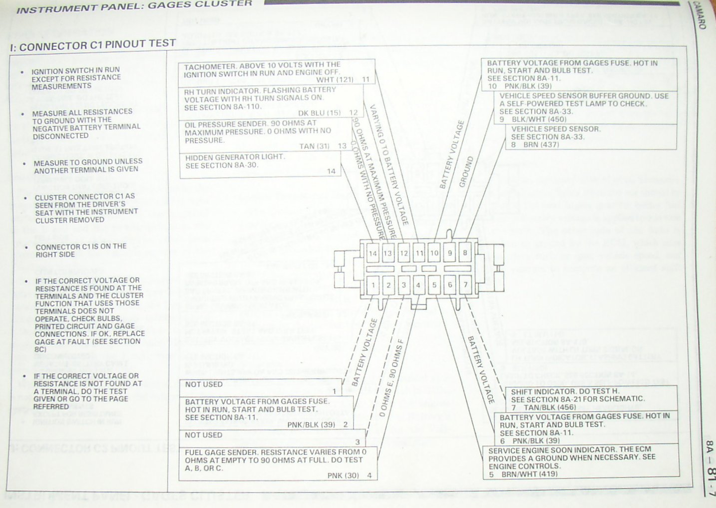
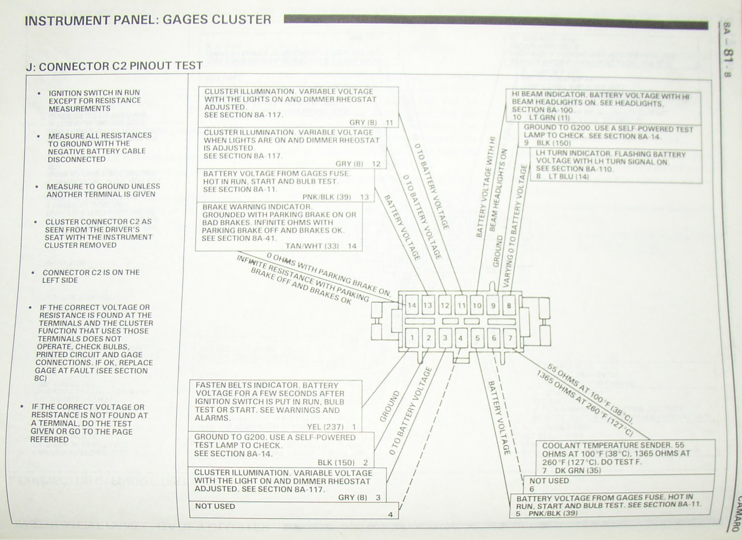
From this drawing you can see that the power for your gages cluster illumination is supplied by pin 3 on connector 2 and pin 3 on connector 1.
The path to ground for these lamps is through pin 2 on connector 2 and pins 2 and 12 on connector 1.
The connector location and pin out for the gages cluster is as bellow.
So if you supply 12 V and ground or 0V to the correct pins you should be able to determine if the bulbs are lighting up or if you have a bad contact or bulb.
I just did the cluster on a 1966 Chevrolet Caprice and I had to use a fine Scotch Brite and WD40 to clean the traces before I could get some of the bulbs to work even with new bulbs installed.
Remember these drawings are from a 1988 Pontiac Firebird service manual so yours might be a little different.
What is most important is to get all conducting surfaces (traces and sockets) nice and clean and grounds as well.
Save yourself some guesswork and try to get a Camaro service manual.
If you can get a star washer of an appropriate size, put that between the terminal and the metal piece. Otherwise, a flat one won't really do any good.
The Firebird & Camaro dashes are substantially different in the details, butt of course very similar in principle. Exactly the same except completely different.
As stated above, I would avoid using ANY form of abrasive or chemical on the PCB unless there is absolutely no other option. Clean them with lacquer thinner, and then after exhausting all other options, resort to the corrosion removal with mild acid (vinegar) followed by a neutralizer (baking soda) and clean water. You might find it helpful to use some clear dielectric grease on the contacts after cleaning them. Same for the bulb sockets: their contacts can get corrosion too.
thanks I cleaned the copper and pcb sheet with a little vinegar and electrical cleaner mild wipe, as i looked at the bulb sockets more closely all the bulb wires had blueish rust and when i pulled the bulbs out the metal wires on the corroded parts ripped on almost 90 percent of the sockets. Im guessing corrosion caused them to not work. I have all new sockets and led bulbs in the mail so ill update this week after i replace them all and put it back together. Ill also clean the ground a bit more by the steering column and the other by radio or console. if none of that works its gota be the headlight switch motor. Wish me luck we making progress