

Valve Train Geometry. Conclusions.

Thread Starter
Supreme Member


Joined: Dec 2005
Posts: 9,919
Likes: 885
From: 53.0907� N, 113.4695� W
Valve Train Geometry. Conclusions.
Here's an arrangement that one of the forum members is putting together.
gbettner is assembling a Gen 1 SBC and the details are in his thread
https://www.thirdgen.org/forums/tech...-thread-3.html
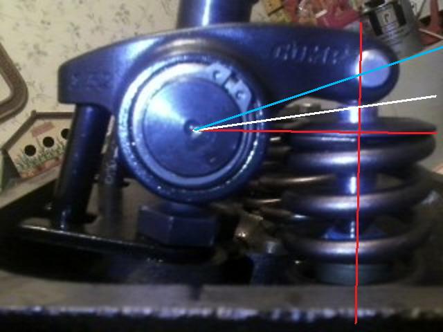
I've marked up his pictures showing the angles involved in the mid-lift method of setting up the correct geometry.
As the method suggests the contact of the rocker tip on the valve at midlift should cross the 90 degree intersection of the valve stem and a line drawn through the centre of the rocker trunion.
When done correctly, this a) minimizes the contact patch on the valve tip and b) the resulting forces are more effectively pushing the valve along it's axis rather than off to the side. Full lobe lift is also realized when correct geometry is achieved.
As far these results look, my thoughts are that it's close. I'm uncertain as to the accuracy of finding mid lift. I don't believe a dial indicator was used but more or less eye balled. That could skew the results enough to make a difference here one way or the other. Admittedly the drawings are a little crude but I think they illustrate the objective fairly well.
The blue line is what we're trying to resolve. Ultimately it should overlap the red line (horizontal or x-axis).
The white line is the contact point. If this were a non-roller tipped rocker, the white line is what would need to be resolved to overlap the red line.


gbettner is assembling a Gen 1 SBC and the details are in his thread
https://www.thirdgen.org/forums/tech...-thread-3.html
I've marked up his pictures showing the angles involved in the mid-lift method of setting up the correct geometry.
As the method suggests the contact of the rocker tip on the valve at midlift should cross the 90 degree intersection of the valve stem and a line drawn through the centre of the rocker trunion.
When done correctly, this a) minimizes the contact patch on the valve tip and b) the resulting forces are more effectively pushing the valve along it's axis rather than off to the side. Full lobe lift is also realized when correct geometry is achieved.
As far these results look, my thoughts are that it's close. I'm uncertain as to the accuracy of finding mid lift. I don't believe a dial indicator was used but more or less eye balled. That could skew the results enough to make a difference here one way or the other. Admittedly the drawings are a little crude but I think they illustrate the objective fairly well.
The blue line is what we're trying to resolve. Ultimately it should overlap the red line (horizontal or x-axis).
The white line is the contact point. If this were a non-roller tipped rocker, the white line is what would need to be resolved to overlap the red line.


Last edited by skinny z; Mar 29, 2014 at 09:35 AM.
Moderator

Joined: Jul 1999
Posts: 17,269
Likes: 170
From: 51�N 114�W, 3500'
Car: 87 IROC L98
Engine: 588 Alcohol BBC
Transmission: Powerglide
Axle/Gears: Ford 9"/31 spline spool/4.86
Re: Valve Train Geometry. Looking for Opinions.
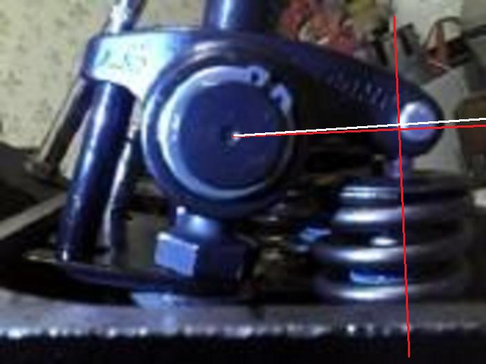
A rocker 90* to the valve stem at mid lift will produce the smallest mark across the tip of the stem. As long as the mark isn't way off to the side of the tip, it doesn't need to be directly over the center of the tip. Location off the direct center isn't as critical as a getting the smallest mark is.
Looking at your pictures I'd almost have to say you need a little longer pushrod. At mid lift, the red line from the trunion to the roller tip isn't passing through the center of the roller.
Looking at your pictures I'd almost have to say you need a little longer pushrod. At mid lift, the red line from the trunion to the roller tip isn't passing through the center of the roller.

Member
iTrader: (2)
Joined: Mar 2013
Posts: 260
Likes: 1
From: Close to Boggstown Indiana ( out in the middle of a corn field)
Car: 89 Iroc, saved from scrapyard
Engine: 350 vortec w/stealth ram
Transmission: 85 corvette 700r4
Axle/Gears: 3.73 posi
Re: Valve Train Geometry. Looking for Opinions.
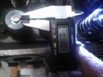
Just to clarify, I DID use a dial indicator for exact measurement down to the thousanth. If you look close you can see part of it on the rocker and the base in the background.
Last edited by gbettner; Mar 20, 2014 at 08:00 PM.
Thread Starter
Supreme Member
Joined: Dec 2005
Posts: 9,919
Likes: 885
From: 53.0907� N, 113.4695� W
Re: Valve Train Geometry. Looking for Opinions.
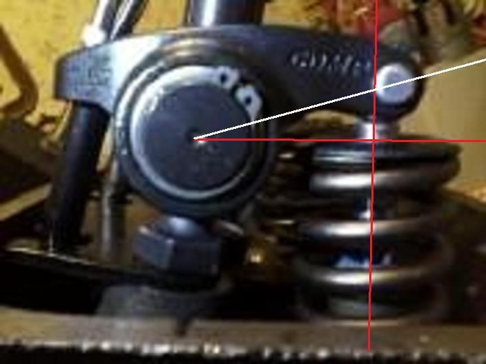
The centre picture is fair representation of the rocker at mid lift. If anything, it looks like the rocker is slightly past 90 degrees at that point. Shortening the pushrod would bring it nose up a little. If you were splitting hairs, the adjustable pushrod I had talked about could be used. Take a little out or add a little and observe the results.
The thing to consider too is that once you achieve that mid lift geometry, the contact patch is the smallest it can be. That's one of test procedures many use to achieve these same results. They don't take the angles into play but rather just keep adjusting lengths until the contact is at it's narrowest.
Last edited by skinny z; Mar 20, 2014 at 08:25 PM.
Thread Starter
Supreme Member
Joined: Dec 2005
Posts: 9,919
Likes: 885
From: 53.0907� N, 113.4695� W
Re: Valve Train Geometry. Looking for Opinions.
A rocker 90* to the valve stem at mid lift will produce the smallest mark across the tip of the stem. As long as the mark isn't way off to the side of the tip, it doesn't need to be directly over the center of the tip. Location off the direct center isn't as critical as a getting the smallest mark is. .
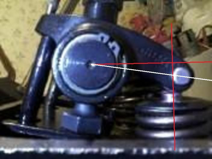
The yellow and green lines are a different but related matter and that's bringing the pushrod /rocker angle into alignment. That's a different beast altogether.
Moderator
Joined: Jul 1999
Posts: 17,269
Likes: 170
From: 51�N 114�W, 3500'
Car: 87 IROC L98
Engine: 588 Alcohol BBC
Transmission: Powerglide
Axle/Gears: Ford 9"/31 spline spool/4.86
Re: Valve Train Geometry. Looking for Opinions.
I see it now. Yeah, a shorter pushrod is needed.
Trending Topics
Moderator
Joined: Jul 1999
Posts: 17,269
Likes: 170
From: 51�N 114�W, 3500'
Car: 87 IROC L98
Engine: 588 Alcohol BBC
Transmission: Powerglide
Axle/Gears: Ford 9"/31 spline spool/4.86
Re: Valve Train Geometry. Looking for Opinions.
I use shaft rockers that have a little tool for determining the shaft height. Once the rocker position is determined, the pushrod length is easy to calculate.
With those pedestal rockers, instead of guessing at pushrod length, buy one of these tools. It takes all the guesswork out.
http://www.summitracing.com/int/part...6789/overview/
Instructions
http://static.summitracing.com/globa.../pro-66789.pdf
With those pedestal rockers, instead of guessing at pushrod length, buy one of these tools. It takes all the guesswork out.
http://www.summitracing.com/int/part...6789/overview/
Instructions
http://static.summitracing.com/globa.../pro-66789.pdf

Supreme Member
Joined: Sep 1999
Posts: 7,072
Likes: 13
From: Philly, PA
Re: Valve Train Geometry. Looking for Opinions.
Skinny Z- while a shorter pushrod might give better geometry, that is sometimes not achievable. Look how close the bottom of your rocker arm is to the radius at the bottom of the rocker stud. If you go too short, there could be contact there.
In situations like that you pretty much have to abandon the quest for perfect rocker geometry and use sticks that are long enough to avoid rubbing parts against eachother.
In situations like that you pretty much have to abandon the quest for perfect rocker geometry and use sticks that are long enough to avoid rubbing parts against eachother.
Member
iTrader: (2)
Joined: Mar 2013
Posts: 260
Likes: 1
From: Close to Boggstown Indiana ( out in the middle of a corn field)
Car: 89 Iroc, saved from scrapyard
Engine: 350 vortec w/stealth ram
Transmission: 85 corvette 700r4
Axle/Gears: 3.73 posi
Re: Valve Train Geometry. Looking for Opinions.
I use shaft rockers that have a little tool for determining the shaft height. Once the rocker position is determined, the pushrod length is easy to calculate.
With those pedestal rockers, instead of guessing at pushrod length, buy one of these tools. It takes all the guesswork out.
http://www.summitracing.com/int/part...6789/overview/
Instructions
http://static.summitracing.com/globa.../pro-66789.pdf
With those pedestal rockers, instead of guessing at pushrod length, buy one of these tools. It takes all the guesswork out.
http://www.summitracing.com/int/part...6789/overview/
Instructions
http://static.summitracing.com/globa.../pro-66789.pdf
Yeah I have one of those pushrod length checkers. I checked with that first and it seemed to check out fine. Only confusing part is you can gain or lose a little on the checker by moving the pushrod back and forth in the guideplate slot so it didn't seem very precise.
Thread Starter
Supreme Member
Joined: Dec 2005
Posts: 9,919
Likes: 885
From: 53.0907� N, 113.4695� W
Re: Valve Train Geometry. Looking for Opinions.
Skinny Z- while a shorter pushrod might give better geometry, that is sometimes not achievable. Look how close the bottom of your rocker arm is to the radius at the bottom of the rocker stud. If you go too short, there could be contact there.
In situations like that you pretty much have to abandon the quest for perfect rocker geometry and use sticks that are long enough to avoid rubbing parts against eachother.
In situations like that you pretty much have to abandon the quest for perfect rocker geometry and use sticks that are long enough to avoid rubbing parts against eachother.
As for giving up, once you've wasted a set of valve guides in a few thousand miles, the quest becomes unavoidable. I don't like the idea of having my heads rebuilt every season.
Thread Starter
Supreme Member
Joined: Dec 2005
Posts: 9,919
Likes: 885
From: 53.0907� N, 113.4695� W
Re: Valve Train Geometry. Looking for Opinions.
....buy one of these tools. It takes all the guesswork out.
http://www.summitracing.com/int/part...6789/overview/
Instructions
http://static.summitracing.com/globa.../pro-66789.pdf

The adjustable pushrod I use, gives me the actual length down to tenths of an inch. Since I'm using a Comp checking tool, ordering Comp pushrods gets me exactly what I'm looking for. Remember that we're talking of selections in .050" increments. Some precision is needed.
Last edited by skinny z; Mar 22, 2014 at 11:34 AM.
Thread Starter
Supreme Member
Joined: Dec 2005
Posts: 9,919
Likes: 885
From: 53.0907� N, 113.4695� W
Re: Valve Train Geometry. Looking for Opinions.
Here's what we're trying to achieve.
This produces the smallest contact on the valve tip as well as maximizing the rocker ratio and limiting side stresses.

This produces the smallest contact on the valve tip as well as maximizing the rocker ratio and limiting side stresses.

Supreme Member
Joined: Sep 2011
Posts: 2,080
Likes: 34
From: Spring Hill, Fl.
Car: 87 iroc-z
Engine: 454
Transmission: th350
Axle/Gears: 3.73
Re: Valve Train Geometry. Looking for Opinions.
IDK, i'd probably run it. the marks look fine.
heres another article with pics about rocker/pushrod geometry.
http://forums.chevyhiperformance.com...sh-rod-length/
might help?
heres another article with pics about rocker/pushrod geometry.
http://forums.chevyhiperformance.com...sh-rod-length/
might help?

Joined: Dec 2005
Posts: 6,499
Likes: 31
From: Macon, GA
Car: 1992 Camaro RS
Engine: Vortec headed 355, xe262
Transmission: T56
Axle/Gears: 9-bolt 3.70
Re: Valve Train Geometry. Looking for Opinions.
skinnyz, thanks for this post. I've learned a hell of a lot about what I had originally thought was complete voodoo.
Thread Starter
Supreme Member
Joined: Dec 2005
Posts: 9,919
Likes: 885
From: 53.0907� N, 113.4695� W
Re: Valve Train Geometry. Looking for Opinions.
IDK, i'd probably run it. the marks look fine.
heres another article with pics about rocker/pushrod geometry.
http://forums.chevyhiperformance.com...sh-rod-length/
might help?
heres another article with pics about rocker/pushrod geometry.
http://forums.chevyhiperformance.com...sh-rod-length/
might help?
If you combine gbettner's marked up drawings and the marks on the valve tip, it could be said that his mark is too wide and the bulk of the valve motion is before TDC.
That said, if the adjustable pushrod can be used and a new round of pictures and valve tip markings can be made, then we can make the proper selection. It may very well be that after running the tests again, the original pushrod (length) MAY in fact , do the job.
I for one, am very interested to see this come to a conclusion.
Thread Starter
Supreme Member
Joined: Dec 2005
Posts: 9,919
Likes: 885
From: 53.0907� N, 113.4695� W
Re: Valve Train Geometry. Looking for Opinions.
Here's an example of another engine I've been working on. This is a ZZZ OEM short block that's slightly decked. AFR 195 heads. Full Comp retro-roller valve train. Valve lift .570".
If you look at the illustration, you see that a perfect VTG relationship has a contact patch of only .027" wide. That's with a valve lift .580".
Examining the pictures of the contact patches, shows the marks to be wider than the target .027". Quite a bit wider in the case of one valve shown.
It should be noted that this same engine, albeit with Brodix heads (but the same valve train) ate up a set of guides in just a few thousand miles. We had put down that failure due to high RPM component separation and troubles inherent in the OEM roller lifter (at revs beyond 6000). Perhaps that was not entirely to blame.
Moderator
Joined: Jan 2000
Posts: 19,664
Likes: 313
Re: Valve Train Geometry. Looking for Opinions.
What's unfortunate is when the aftermarket offers parts which cannot possibly work with other aftermarket parts, and someone selects parts without consideration for that synergy. I recently encountered that on a Dart/SBC 385 and had to acquire higher offset rocker from Comp to clear the springs and get the roller over the stem without putting the push rod into the intake flange. It's a good thing Comp recognizes this and offers those. You may have a similar situation someday.
Thread Starter
Supreme Member
Joined: Dec 2005
Posts: 9,919
Likes: 885
From: 53.0907� N, 113.4695� W
Re: Valve Train Geometry. Looking for Opinions.

Member
iTrader: (2)
Joined: Mar 2013
Posts: 260
Likes: 1
From: Close to Boggstown Indiana ( out in the middle of a corn field)
Car: 89 Iroc, saved from scrapyard
Engine: 350 vortec w/stealth ram
Transmission: 85 corvette 700r4
Axle/Gears: 3.73 posi
Re: Valve Train Geometry. Looking for Opinions.
Emailed you the new round of pics Skinny (if you don't mind doing your thing with them again). After recieving the new adjustable pushrod I determined that exactly 7 1/2 turns out from the fully collaped position was exactly equal to the stock pushrod. I turned the tool exactly 1 turn shorter to 6 1/2 turns and ran the test again. Wear pattern on valve looks same or bigger if you ask me. Calipers show it at about 0.127 wide the best I can tell if that matters.
Looks like each half turn is about a 1/16th of an inch. Each full turn is 1/8th inch?
Stock seems to measure 7 and 3/16ths. half turn down on the adjustable seems to be 7 and 1/8th. Not sure but should I only be testing "full turns" with the both lines on the adjustable pushrod lined up as that's the ordering increments?
Last edited by gbettner; Mar 24, 2014 at 04:20 PM.
Thread Starter
Supreme Member
Joined: Dec 2005
Posts: 9,919
Likes: 885
From: 53.0907� N, 113.4695� W
Re: Valve Train Geometry. Looking for Opinions.
Your OEM roller block should have 7.2" pushrod (7.195'). That's stock. The pushrod tool fully collapsed has a 6.8" length. Each full turn is .050" or 1/20th of an inch. Eight turns should add .400" to the checker and equal your stock pushrod. 7 1/2 is close considering we're dealing with how GM measures pushrods and how Comp does it.
Joined: Sep 2003
Posts: 25,895
Likes: 429
From: Pittsburgh PA
Car: 89 Iroc-z
Engine: 555 BBC Turbo
Transmission: TH400
Axle/Gears: MWC 9� 3.00
Re: Valve Train Geometry. Now With MORE Pictures.
http://www.aera.org/engine-professio...cker-geometry/
http://www.aera.org/ep/downloads/ep1...2010_20-30.pdf
Good article and you seem to have this figured out. Measure half lift and you want the rocker body to be positioned as displayed in the article.
I install valve micrometer and set it to half my lift. Then install pushrods til i get 90 deg rocker trunion to contact centerline to valve stem alignment. Thats your pushrod length.
Other way guys do it, they install dial indicator at edge of rocker tip perpendicular to valve stem plane. They adjust pushrod length and measure resulting sweep of rocker tip.
Thread Starter
Supreme Member
Joined: Dec 2005
Posts: 9,919
Likes: 885
From: 53.0907� N, 113.4695� W
Re: Valve Train Geometry. Now With MORE Pictures.
The paper by Jim Miller is an eye opener. This article clears up any misconceptions.
I'd like to run another test with an even longer pushrod and observe the contact patch.
Gbettner was getting an increasingly narrower patch as they pushrod length increased even beyond what was considered to be the correct mid lift geometry. A different measuring technique as illustrated in Miller's paper puts a different light on the subject. A light that brings a few answers more into focus. Such as why did the contact get narrower as length increased beyond optimum? Perhaps because that wasn't optimum and the measurements are off slightly.
If Gbettner can bear with me, I'll rework those drawings (later today) and post them.
Perhaps I'll have another couple of pictures to work through too.
Last edited by skinny z; Mar 25, 2014 at 10:16 AM.
Joined: Sep 2003
Posts: 25,895
Likes: 429
From: Pittsburgh PA
Car: 89 Iroc-z
Engine: 555 BBC Turbo
Transmission: TH400
Axle/Gears: MWC 9� 3.00
Re: Valve Train Geometry. Now With MORE Pictures.
Also account for hydraulic lifter flex if not using a light enough check spring and not a fully extended pumped up lifter. I used to make solid lifters out of spare ls7 lifters and use them for checking. Worked great
Thread Starter
Supreme Member
Joined: Dec 2005
Posts: 9,919
Likes: 885
From: 53.0907� N, 113.4695� W
Re: Valve Train Geometry. Now With MORE Pictures.
We're using a stacked up hydraulic lifter to simulate a solid in these tests. Full spring too so that slack is taken care off.
I've been using my plotting points (for the drawings) as the centre of the rocker trunion and the point where the roller tip contacts the valve. Millers paper describes the measuring points as being the centre of the trunion and the centre of the roller tip. That puts a whole new spin on the approach and may explain why as the pushrod length was extended beyond stock length, the contact patch became increasingly narrower.
Further to this, I was dissecting the parts list of a particulat Gen 1 SBC build and came across a retro-roller setup that used a 7.450" pushrod. That's more than 2/10ths longer than what's considered as the norm for these engines (all else being equal like heads and deck, etc.)
Certainly more testing needs to be done.
Thread Starter
Supreme Member
Joined: Dec 2005
Posts: 9,919
Likes: 885
From: 53.0907� N, 113.4695� W
Re: Valve Train Geometry. Conclusions.
Here it is.
We've gone from the "stock" length of 7.2" ( for OEM lifters) in the original pictures to a 7.4". There's room for improvement at 7.5" however the contact point gets very close to the exhaust side of the valve. The decision was made to err on the short side.
It should be noted that the approach was changed after the original pictures were posted. It was found that it's the centre of the axis of the roller tip that is the data point were looking for when using the mid lift method rather than the contact point on the valve tip. The drawings were modified to reflect that change. Unfortunately, a couple of the conversations that follow the initial posting don't make much sense now however I hope the contributors understand the changes made.
7.4" zero lift

7.4" mid lift
7.4" max lift

7/4" contact

We've gone from the "stock" length of 7.2" ( for OEM lifters) in the original pictures to a 7.4". There's room for improvement at 7.5" however the contact point gets very close to the exhaust side of the valve. The decision was made to err on the short side.
It should be noted that the approach was changed after the original pictures were posted. It was found that it's the centre of the axis of the roller tip that is the data point were looking for when using the mid lift method rather than the contact point on the valve tip. The drawings were modified to reflect that change. Unfortunately, a couple of the conversations that follow the initial posting don't make much sense now however I hope the contributors understand the changes made.
7.4" zero lift

7.4" mid lift

7.4" max lift

7/4" contact

Supreme Member
Joined: Sep 1999
Posts: 7,072
Likes: 13
From: Philly, PA
Re: Valve Train Geometry. Conclusions.
Skinny- draw two lines on that graph going straight up through the rocker stud and the valve stem. Notice they are not parallel. The higher the rocker sits on the rocker stud, the more it pushes the rocker tip towards the exhaust side of the valve stem tip.
Like Vader said, there's more to it that just the sweep width. Things MOVE POSITION in absolute terms as you lengthen the sticks. 7.4" is looking like it's already a bit TOO LONG to me, though I admit it's a little tough to tell from the pics.
You're in the ballpark there between the 7.2 and 7.4" sticks. I don't think you're going to make some kind of horrible, collossal mistake anywhere in that range.
Thread Starter
Supreme Member
Joined: Dec 2005
Posts: 9,919
Likes: 885
From: 53.0907� N, 113.4695� W
Re: Valve Train Geometry. Conclusions.
Skinny- draw two lines on that graph going straight up through the rocker stud and the valve stem. Notice they are not parallel. The higher the rocker sits on the rocker stud, the more it pushes the rocker tip towards the exhaust side of the valve stem tip.
Like Vader said, there's more to it that just the sweep width. Things MOVE POSITION in absolute terms as you lengthen the sticks. 7.4" is looking like it's already a bit TOO LONG to me, though I admit it's a little tough to tell from the pics.
You're in the ballpark there between the 7.2 and 7.4" sticks. I don't think you're going to make some kind of horrible, collossal mistake anywhere in that range.
Like Vader said, there's more to it that just the sweep width. Things MOVE POSITION in absolute terms as you lengthen the sticks. 7.4" is looking like it's already a bit TOO LONG to me, though I admit it's a little tough to tell from the pics.
You're in the ballpark there between the 7.2 and 7.4" sticks. I don't think you're going to make some kind of horrible, collossal mistake anywhere in that range.
Unfortunately, as you state, the limitations of the parts used may prevent the realization of a VGT that's ideal in every sense. Conventional thinking puts the emphasis on keeping the contact as narrow as possible however there are inevitably compromises to be made.
I can tell you that a couple of tenths, (that's the range you've selected), could make the difference between these guides lasting a long time (as in plenty miles, not drag strip passes) as opposed to them getting worn quickly. As for this install, gbettner made the choice to shorten up on the pushrods. Add to that the amount he'll gain from the lifter pre-load (1/2-3/4 turn on a 24tpi stud is about .030") and he should get a long service life out of those heads. (Provided of course everything else is up to the task.)
Supreme Member
Joined: Sep 1999
Posts: 7,072
Likes: 13
From: Philly, PA
Re: Valve Train Geometry. Conclusions.
Skinny- since you've obviously throught it through to this point, let me give you the missing piece that most people don't know about stock valvetrain geometry.
The factory NEVER used the mid-lift rule. Not even close. Remember they use scrubber rocker arms. The friction sliding them across the valve tip is NOT linear. It increases with spring tension. So the factory allows a lot more movement of the rocker pallet across the valve stem in the lower lifts when spring tension is low, while it remains nearly stationary as it approaches max lift. In short, that IS the factory solution for minimizing valve guide wear. Make all the side-thrust happen while spring tension and rocker tip friction is lowest.
In short, they ALWAYS use sticks that are shorter than optimal according to the mid-lift rule. And on a stock head it's a bit difficult to install long enough sticks for optimal geometry without pushing the contact area way out towards the exhaust side of the valve tip.
Let that sink in for a moment and you should be thinking something like "Oh, so THAT'S why I've been beating my head against the wall over this!!"
With roller tip rockers you obviously don't have nearly the friction issues to deal with of a stock scrubber-rocker. So you can play with the geometry in a fairly wide range and it'll still work just fine, valve guides will live a long life either way. But the location of the contact area on the valve tip WILL get pushed towards the exhaust side rather dramatically as you install sticks long enough for optimum mid-lift geometry.
Here's hoping this post puts your mind more at ease, rather than making you want to pull more of your hair out.
Last edited by Damon; Mar 29, 2014 at 08:59 PM.

Joined: Sep 2009
Posts: 3,776
Likes: 101
From: Spokane WA
Car: 92 Lingenfelter Z28 articwhite
Engine: Aluminum 615BBC
Transmission: Th400wbrake/curri entps9" locker
Axle/Gears: 4.11/4.30/4.56
Re: Valve Train Geometry. Conclusions.
just looking at the pics..ya need a shorter pushrod. start knocking off. 100thow at a time..
get it back. to just inside the mid of the tip....(no did not read all the post just a few)
but from the pics....its way way off.
use the push rod checker. set to the spot on the valve tip ya want to rid at.. the measure the checker to get the length.
so ya need a caliper to check it...i use one that is larg size.(up to 20")lol arospace was my old job.
ya cant buy the right size??? the guys who make them for compcams. will make them for you.. in 3 days. cost about $130 bucks...but every body knows this....right?
Last edited by articwhiteZ; Mar 29, 2014 at 09:17 PM.
Thread Starter
Supreme Member
Joined: Dec 2005
Posts: 9,919
Likes: 885
From: 53.0907� N, 113.4695� W
Re: Valve Train Geometry. Conclusions.
Skinny- since you've obviously throught it through to this point, let me give you the missing piece that most people don't know about stock valvetrain geometry.
The factory NEVER used the mid-lift rule. Not even close. Remember they use scrubber rocker arms. The friction sliding them across the valve tip is NOT linear. It increases with spring tension. So the factory allows a lot more movement of the rocker pallet across the valve stem in the lower lifts when spring tension is low, while it remains nearly stationary as it approaches max lift. In short, that IS the factory solution for minimizing valve guide wear. Make all the side-thrust happen while spring tension and rocker tip friction is lowest.
In short, they ALWAYS use sticks that are shorter than optimal according to the mid-lift rule. And on a stock head it's a bit difficult to install long enough sticks for optimal geometry without pushing the contact area way out towards the exhaust side of the valve tip.
I think you might find that if you were to examine an entirely stock late model roller valve train (from an SBC) you'll see a decent VGT. Our ZZZ block, when all of the tolerances are considered, comes in around a 1/10th less than ideal. I can't say that for any of the older flat tappet engines. I don't know. A lot was left on the table in the old days because it didn't matter much and maybe to the OEMs is still doesn't. Today, I don't think I would kid myself thinking that the OEMS don't realize the benefit of the reduced friction that comes from lessening the amount the rocker travels across the valve tip.
With roller tip rockers you obviously don't have nearly the friction issues to deal with of a stock scrubber-rocker. So you can play with the geometry in a fairly wide range and it'll still work just fine, valve guides will live a long life either way. But the location of the contact area on the valve tip WILL get pushed towards the exhaust side rather dramatically as you install sticks long enough for optimum mid-lift geometry. [/quote]
I'm glad you brought the roller tip up as a shoe type rocker isn't part of the equation. The benefits of the roller tip are, as you describe, the reduced friction from the elimination of the sliding contact.
I'll have to argue with you on your other point. If the geometry is off, that is to say, you ignore the width of the contact area for the sake of keeping the contact centred, then you'll kill your guides if you've compromise by more than a couple of tenths. I'd say that if you give up a tenth on the optimum length, then you're risking early guide destruction. How early depends on a lot of things. So does how sensitive any given combination will be to a poor setup. What I can say from direct (and all too recent) experience is that 3/10s too short (from the "ideal" mid lift geometry) had my witness mark dead centre but very wide. The guides were done in about 3000 miles. I made the mistake of going for centre over width.
You're also giving up information that's being passed along by the cam lobe. Why do that?
Keep the movement as small as possible, keep the contact within reasonable boundaries of the valve tip and I think that'll give the best results. At least from a mathematical standpoint it does. Efficiency rules.
I understand all of your points. I have thought this through like you said and I've got some background too.
My hair is fine.
Thanks.
Thread Starter
Supreme Member
Joined: Dec 2005
Posts: 9,919
Likes: 885
From: 53.0907� N, 113.4695� W
Joined: Sep 2009
Posts: 3,776
Likes: 101
From: Spokane WA
Car: 92 Lingenfelter Z28 articwhite
Engine: Aluminum 615BBC
Transmission: Th400wbrake/curri entps9" locker
Axle/Gears: 4.11/4.30/4.56
Re: Valve Train Geometry. Conclusions.
ok ill try to help.. this is going to sound dumb..But.
make sure all your rockers are all the way down on the stud. with the poly lock cup facing up(the right way)... just checking..go with this..
make sure your using a dummy lifter/solid. if this is a hydraulic cam.
making sure its the right length.
you can use your full power springs. but i go to ace hardware and pick up some small springs (50cents ea)
now when your all set. run your checker down to the spot your rocker tip rides in the middle of the valve.. then back it down to the start of the sweep. starts just before the center of the tip of the valve..
now measure your caliper to get the right size of push rod ya need..easy easy.
you will need to do this on about half of the valves...to get a all over ballpark size. of push rods.. i just a set and had to get almost 200thow longer over stock..some time long some times short..
hope this helps
Last edited by articwhiteZ; Mar 29, 2014 at 10:11 PM.
Supreme Member
Joined: Sep 2011
Posts: 2,080
Likes: 34
From: Spring Hill, Fl.
Car: 87 iroc-z
Engine: 454
Transmission: th350
Axle/Gears: 3.73
Re: Valve Train Geometry. Conclusions.
Here it is.
We've gone from the "stock" length of 7.2" ( for OEM lifters) in the original pictures to a 7.4". There's room for improvement at 7.5" however the contact point gets very close to the exhaust side of the valve. The decision was made to err on the short side.
It should be noted that the approach was changed after the original pictures were posted. It was found that it's the centre of the axis of the roller tip that is the data point were looking for when using the mid lift method rather than the contact point on the valve tip. The drawings were modified to reflect that change. Unfortunately, a couple of the conversations that follow the initial posting don't make much sense now however I hope the contributors understand the changes made.
7.4" zero lift
7.4" mid lift

7.4" max lift
7/4" contact
We've gone from the "stock" length of 7.2" ( for OEM lifters) in the original pictures to a 7.4". There's room for improvement at 7.5" however the contact point gets very close to the exhaust side of the valve. The decision was made to err on the short side.
It should be noted that the approach was changed after the original pictures were posted. It was found that it's the centre of the axis of the roller tip that is the data point were looking for when using the mid lift method rather than the contact point on the valve tip. The drawings were modified to reflect that change. Unfortunately, a couple of the conversations that follow the initial posting don't make much sense now however I hope the contributors understand the changes made.
7.4" zero lift
7.4" mid lift
7.4" max lift
7/4" contact
my opinion as just a hobbyist may not mean much, but i'll give my thoughts.
from these pictures i feel the pushrod is too long. the wear mark shows it towards the exhaust side too. just doesnt seem right to me. as stated the 7.4's will probably work, but i see the guides wearing out quicker that way. JMO,...and it may not mean much?

Thread Starter
Supreme Member
Joined: Dec 2005
Posts: 9,919
Likes: 885
From: 53.0907� N, 113.4695� W
Re: Valve Train Geometry. Conclusions.
ok ill try to help.. this is going to sound dumb..But.
make sure all your rockers are all the way down on the stud. with the poly lock cup facing up(the right way)... just checking..go with this..
make sure your using a dummy lifter/solid. if this is a hydraulic cam.
making sure its the right length.
you can use your full power springs. but i go to ace hardware and pick up some small springs (50cents ea)
now when your all set. run your checker down to the spot your rocker tip rides in the middle of the valve.. then back it down to the start of the sweep. starts just before the center of the tip of the valve..
now measure your caliper to get the right size of push rod ya need..easy easy.
you will need to do this on about half of the valves...to get a all over ballpark size. of push rods.. i just a set and had to get almost 200thow longer over stock..some time long some times short..
hope this helps
The tests that are the subject of this thread have OEM hydraulic lifters and one has been stacked up as a solid. The real trick here would have been to leave a gap equal to the amount lost due to lifter preload but you can work that value out at the tail end. Same as if you were to make a serious move with heads gaskets. Up or down on the gaskets any significant amount and the pushrod length may need to be revisited. Same with getting the heads milled and as in my case, swapping out short blocks AND changing to a lifter with a different seat height.
For a retro-fit roller the lifters that can't be stripped down (at least mine can't) unless you cut the rivet's out of the link bar, checking springs are an alternative but there's a degree of misinformation because they aren't strong enough. You could use your hydraulic roller and take all of the preload out of it by collapsing it fully. That's a known value and again I suppose you can add it on in the final calculations.
Selecting several valves to examine would be standard procedure as well. Selecting pushrods based on individual cylinders or valves I think would be beyond the scope of this build or mine. If one stands out more than the rest, then there are other issues.
Incidentally , I did purchase my checking springs at Ace.
Last edited by skinny z; Mar 30, 2014 at 08:04 AM.
Thread Starter
Supreme Member
Joined: Dec 2005
Posts: 9,919
Likes: 885
From: 53.0907� N, 113.4695� W
Re: Valve Train Geometry. Conclusions.
my opinion as just a hobbyist may not mean much, but i'll give my thoughts.
from these pictures i feel the pushrod is too long. the wear mark shows it towards the exhaust side too. just doesnt seem right to me. as stated the 7.4's will probably work, but i see the guides wearing out quicker that way. JMO,...and it may not mean much?
from these pictures i feel the pushrod is too long. the wear mark shows it towards the exhaust side too. just doesnt seem right to me. as stated the 7.4's will probably work, but i see the guides wearing out quicker that way. JMO,...and it may not mean much?
Here's a link to a great paper written by a patent holder on VTG procedure.
http://www.aera.org/engine-professio...cker-geometry/
or
http://www.aera.org/ep/downloads/ep1...2010_20-30.pdf
I can tell you first hand (with pictures too) what happens when the pursuit of the centred contact outweighs that of trying to get as little movement as possible across the valve tip (as in narrow contact). It's valve guide death. Interestingly enough, if this were a drag race only engine, it would have lasted a dozen seasons. But several thousand miles getting beat up on the street crushed the guides.
The mid-lift rule has that objective in mind. You just have to set limits. I'll go with this rather than repeat what I've done before.
Last edited by skinny z; Mar 30, 2014 at 08:06 AM.

Thread
Thread Starter
Forum
Replies
Last Post
355tpipickup
Tech / General Engine
9
Sep 13, 2015 11:35 PM