When you click on links to various merchants on this site and make a purchase, this can result in this site earning a commission. Affiliate programs and affiliations include, but are not limited to, the eBay Partner Network.
Hi All,
I am having trouble finding this answer, so I thought this would be the best place to ask the question and have the answer available to everyone, as it is a gap in the info available about this.
Question 1:
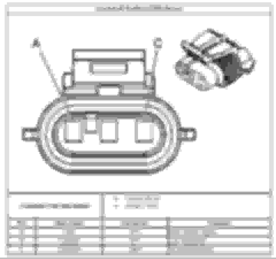
Using a Vortec distributor as the Cam Position Sensor, and looking down the connector at the pins, are these the correct wiring diagrams?
Where C= 12v (Red 39 on 0411 PCM)
B=signal from dizzy (Blue 73 on 0411 PCM)
& A= Low Reference / ground from PCM? (Blue 61 on 0411 PCM)
Question 2:
For the EFI Connection supplied 24x crank sensor, is the below diagram correct:
Where A=Sensor signal (Blue 12 on 0411 PCM)
B= Low Reference / Ground by PCM (Blue 21 on 0411 PCM)
& C=12v (Blue 2 on 0411 PCM)
I'll edit this once someone posts the correct CONFIRMED wiring.
If Pocket or Wildside can weigh in on this it'd be great.