When you click on links to various merchants on this site and make a purchase, this can result in this site earning a commission. Affiliate programs and affiliations include, but are not limited to, the eBay Partner Network.
DFI and ECMDiscuss all aspects of DFI (Digital Fuel Injection), ECMs (Electronic Control Module), scanners, and diagnostic equipment. Fine tune your Third Gen computer system for top performance.
I can't find any threads relating directly to making DIY cables for the earlier cars, certainly not using USB, so is there anything else I will need? I've found diagrams using serial cables, which feature more resistors, but I don't think I'll need those with the FT232.
I know about the 10kohm resistor between pins A and B and I've purchased a pack of those to experiment with too. And I know I'll have to tap into Pin E on the ALDL connector to get data.
My ECM is a 1226865, which I believe is only 160 baud, and I was planning to use Tunerpro, or else WinALDL if I can't get that to work.
Is there 12v to the ALDL connector on these early cars? I'm slightly worried that the 5V limit on that serial cable might mean it gets fried...
Are there any issues with running the car with cable connected? Should I make the 10k ohm resistor switchable? I've heard that the car won't run properly with those pins bridged.
Ah, thanks for the warning! Checking the Service manual, I guess pin G to the fuel pump might have 12V. I'll be especially careful not to mis-wire to that. I should only be using pins A and E and possibly B. The service manual does advocate driving with the ALCL scanner connected, although it's not clear if it bridges pins A and B to do so.
The ALDL serial data is 0 - 5 V, so good to go there. Wouldn't hurt to place a 270 ohm resistor in series with the cable.
Note that there are locations in the ALDL port that do have 12 volts on them. So need to be careful connecting to the port.
RBob.
I've done a bit more googling and I can't find any reference to a 270 ohm resistor anywhere else. Why would this be useful? And would it go on the connection to pin A or pin E?
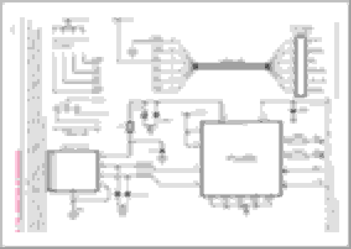
The reason for the 270 ohm resistor is for some protection of the TTL to USB chip. Here is the schematic of the cable you purchased. Note how FTDI placed a 100 ohm resistor in series with the TX data line.
You can do similar on the RX line into the chip (on the yellow wire).
Thanks for the information and circuit diagram - they're invaluable! Interestingly, the wire colours don't tally with what I've got in front of me
Fortunately I've found this diagram online, and the colours referred to in the firebirdnation post also tally with the same colours.
Referring to your wiring diagram, it seems I'm connecting black (GND) to pin A (GND), which is logical, and then joining RXD and TXD together to connect into pin E (data). Does that make sense?
The 10k ohm resistors haven't arrived yet, but I'll connect it across pins A and B with a 5V switch.
I wonder if it'll work....!
I don't have a 270ohm resistor for RXD available to me, but as it takes 5V it'll probably be ok, won't it?
I opened up my 12 to 16 pin cable to check the connections, and found no connection to pin E. Annoying, but I could possibly re-pin the ALCL connector on my car to M and then use that... so I went out to my car to check..
And found no pin E.
My car doesn't seem to have any kind of data connection... only pins A for ground, B for test, C for the AIR pump and D for 'check engine light'.
Am I missing something? I assumed there must be some kind of data link if there's an ECM on board. Do I connect to pin D? The shop manual does refer to connecting an ALCL tool, so information must come from somewhere....
Sadly my cut-in-half 12-16 pin converter is proving quite useless. Only pins A, M, G and K are connected.
Black - A
Red - K
Orange - G
Brown - M
Green - Not connected to any pins!
Yellow - Not connected to any pins!
Bizarre...
I suppose I could re-pin D to M, and B to K....
Last edited by ndndndnd; Aug 13, 2019 at 02:24 PM.
Well, I've tried every which way I can I'm not getting any data. Frustrating!
I tried to solder some paperclips (as I saw suggested elsewhere) to provide some temporary ALDL connectors and tried to use those. No dice, very low connection numbers - 1-4. I got some RAW data, but just junk which I guess came from the paper clips rattling in the connectors as the engine idled. Tried again using piece of copper wire and crocodile clips, checked and double-checked the connections, I get the pulsing CEL light, but absolutely no data whatsoever. Just a little bit of junk if I pull out the wire and tap it on the ALDL connector.
I've tried everything I can think, including different baud rates and nothing seems to make any difference. I'm getting 5V between A-B and a small amount voltage between A-D.
I've been using WINALDL as I can't find the correct ADX/BIN/ADS files for my ECM for tunerpro, plus tunerpro is really complicated when I all I really want is to verify the CTS reading the ECM is seeing!
I'm going to make up my FT232 cable with properly soldered joints to my cut-off and 12-pin connector and then switch the pins around in the ALDL socket to absolutely confirm it's not a connection issue. Both WINALDL and Tunerpro confirm that my FT232 cable is functioning properly. I've selected the correct COM port and switched COM ports and USB ports on my (old Vista) laptop to try to rule that out too...
...but is there any other reason why I'm not getting any data?
This is a really informative thread, and it's hard to believe the technology is only 35 years old and we are having trouble communicating with it. Reminds me of this:
My next guess is to measure the voltage between Pins A and D with a 10kohm resistor between pins A and B. I think I read somewhere that I should see spikes of 5V as data is transferred. Can anyone confirm or say what I should see instead? I did measure voltage between A and D without the resistor in place and I got a trace voltage, but I'm trying to establish if packets of information are actually being transferred. I'm wondering if my eBay cable is faulty, although Tunerpro reckons it's fine...
Yes, that pulsing occurs with the 10kohm resistor between pins A and B, which is what makes me think the ECM is behaving properly. However, I'm not sure if this signal is being relayed to Pin D - although I haven't checked how they're wired, so perhaps the CEL will only pulse if signal is present at Pin D - however I was thinking I'd check for pulsing (5V?) signal at Pin D. If that's present, I'm starting to suspect my FT232 cable may be faulty...
A little bit of googling led me to this link https://www.trishtech.com/2015/01/te...r-using-putty/ and a piece of software called puTTY. I've run my cable through this and it would seem my cable is fine, even when tested at different baud rates.
Finger points back at the car. I'm sure I've read somewhere about the cigarette lighter being rusty stopping the signal...
ACC fuse and cigarette lighter seem fine, so I've parked that idea for now.
I measured voltage between pins A and D with the Key On, Engine Off and got a trace voltage of 0.8 or so. I tried again with the 10kohm resistor between Pins A and B and re-read the Voltage between Pins A and D. It now read nearly 12V! The voltage fluctuated between about 8V and just under 12V, which suggests me that the ECM is trying to transfer data, albeit at a much higher voltage than I was expecting! Is this my problem?
RBob, you mentioned a 270ohm resistor before - could this be the difference between the FT232 absorbing usable information and being overwhelmed by the voltage?
Cheers,
ND
ETA: This is interesting: https://www.techedge.com.au/vehicle/aldl160/aldl_hw.htm
Apparently 12V through the data port is normal for some cars. I need to sit down and absorb this some more. I'm not sure how this serial design could relate to the FT232RL thing I have...
Last edited by ndndndnd; Aug 24, 2019 at 02:47 PM.
I'm looking at this diagram and scratching my beard.
This diagram is a for a circuit that is designed to work with a 12V output. I'm only working at 160 baud, so apparently I can ignore Q1, D1 and R3. The website says "Q2 converts the ECM's ALDL serial output to a pseudo RS232 voltage." which I'm guessing is something that later ECM's don't need as they run at 5V, which is directly compatible with FT232...
The thing that puzzles me about that diagram is that it omits the 10kohm resistor between pins A and B ,which I presume is still needed to put it into diagnostic mode. I could buy some NPN transistors and have a play about... but the connections do seem very different to what's mentioned elsewhere....
...and this article keeps saying RS232 rather than FT232, and a quick google suggests they're a bit different. Does FT232 just means it talks to USB ports rather than serial ports?
If you go on the WinALDL website there is a circuit diagram to build a ALDL to serial cable this is the link http://winaldl.joby.se/aldlcable.htm
I built the one without the external 12v supply and it worked perfectly. I purchased a quality serial to usb cable and connected to the PC via that. Looking at the circuitry it looks like it just inverts the data stream. I just used three wires with flat lugs on the ends that I could push into the ALDL connector terminals.
On the early Y body cars you need the 10k resistor to put the ECM in ALDL mode. Also the early Y body cars do not have 12v present at the connector, I imagine F body cars are similar.
Hopefully this helps.
ACC fuse and cigarette lighter seem fine, so I've parked that idea for now.
I measured voltage between pins A and D with the Key On, Engine Off and got a trace voltage of 0.8 or so. I tried again with the 10kohm resistor between Pins A and B and re-read the Voltage between Pins A and D. It now read nearly 12V! The voltage fluctuated between about 8V and just under 12V, which suggests me that the ECM is trying to transfer data, albeit at a much higher voltage than I was expecting! Is this my problem?
RBob, you mentioned a 270ohm resistor before - could this be the difference between the FT232 absorbing usable information and being overwhelmed by the voltage?
Cheers,
ND
ETA: This is interesting: https://www.techedge.com.au/vehicle/aldl160/aldl_hw.htm
Apparently 12V through the data port is normal for some cars. I need to sit down and absorb this some more. I'm not sure how this serial design could relate to the FT232RL thing I have...
Odds are the FT232 chip input popped due to the voltage. I had forgotten that the CCC ECMs run the ALDL stream through the lamp driver module. The 270 ohm resistor may have been enough to protect the FT232 chip.
The other circuits that are being posted are for a serial port on the laptop, not USB.
The other circuits that are being posted are for a serial port on the laptop, not USB.
RBob.
Yep that�s correct. I built the serial cable because it was cheap and easy, then purchased a nine pin rs232 to usb conversation cable and connected to the ECM through it. The cable I bought has an orange LED that flashes green when data is flowing, which is quite helpful when you are trying to get it to work.
If you go on the WinALDL website there is a circuit diagram to build a ALDL to serial cable this is the link http://winaldl.joby.se/aldlcable.htm
I built the one without the external 12v supply and it worked perfectly. I purchased a quality serial to usb cable and connected to the PC via that. Looking at the circuitry it looks like it just inverts the data stream. I just used three wires with flat lugs on the ends that I could push into the ALDL connector terminals.
On the early Y body cars you need the 10k resistor to put the ECM in ALDL mode. Also the early Y body cars do not have 12v present at the connector, I imagine F body cars are similar.
Hopefully this helps.
That's actually hugely helpful - thank you. I've gone back to look at the winaldl serial instructions and they're starting to make mores sense to me. Unlike the later cars which can communicate directly through the RS232, I need to create the circuit shown to convert the signal, as referred to on www.techedge.com.au
Originally Posted by RBob
Odds are the FT232 chip input popped due to the voltage. I had forgotten that the CCC ECMs run the ALDL stream through the lamp driver module. The 270 ohm resistor may have been enough to protect the FT232 chip.
The other circuits that are being posted are for a serial port on the laptop, not USB.
RBob.
I've just checked my cable again through puTTY, and it seems to check out, so hopefully I haven't damaged the circuit by 'buzzing' it with a higher voltage.
You're right that the circuits are all discussing a serial connection, but they still refer to RxD, TxD and GND, which seem to translate directly into the wiring for the FT232. I think this means I can wire up the winaldl circuit directly to the FT232 connections, and then the FT232 can communicate with the USB.
I assume I won't need to worry about any 12V inputs, as the USB will power the FT232 itself - hence I'll omit the DTR power connection and R2 resistor mentioned.
Looking closely, the techedge and winaldl circuits are actually the same - except the winaldl circuit omits the TxD circuit, as the early ALDL system can't receive information from the computer. Apart from that, the winaldl circuit also includes R4 - a 1.5kohm resistor bridging across the NPN transistor. As mine's a carb'd car, I guess I'll need that too.
I guess I'd better hit the electronics section of eBay! Thanks Greg and RBob, I'll keep you informed of how I get on!
You will need that 10k resistor on pin 2 (supplied by 5 or 12v). When the transistor turns on it puts that high level (12 or 5v) low (0v). That is how pin 2 is receiving an inverted signal.
Hope that makes sense.
Hmmm... I do have a 5V wire (shown red on the picture I posted higher up in post #6). Perhaps that's the equivalent of the DTR and I need to put a 10kohm resistor between the red (5V) and white wires (RxD)?
The inverted signal bit doesn't make much sense - but that's because I know ZIP about electronics and have to rely on good people like you!
That will work or you can connect the the DTR (data terminal ready) control line of the serial connector. IIRC when a serial terminal is active it lifts DTR (ie raises the voltage above 0v normally 5v these days). The device at the other end of the cable lifts RTS (request to send) and the the terminal lifts CTS (clear to send). This is the handshaking that is done before data is transferred. Anyway that�s a quick description on how RS232 works. So in the circuit above It is known the DTR will be high so it is being used as a voltage source.
So now a quick description of what that transistor is doing. The transistor is inverting the data stream from the car. The first thing to remember is that if you have a wire connected to a 12v supply and you attach a 10k resistor to one end you will be able to measure 12v on each side of the resistor. If you then connect the other end of the resistor to ground you will measure 12v on one side of the resistor and 0v on the other side. Make sense so far? The transistor has the other end of the 10k resistor connected to the collector. Think or the transistor as a switch that is turned on and off by applying voltage to the base (actually transistors work on current not voltage in this case current flowing into the base and out the emitter but it�s easier to think of voltage being applied to the base to turn the transistor on). When the transistor is turned on current can flow between the collector and emitter. When this happens that 10k resistor is connected to ground and 0v are present at the receive terminal.
So putting it all together when the data signal from the car is high the transistor turns on and the data signal on the receive pin is low. Likewise when the data stream from the car is low the transistor is off and the data stream on the receive pin is high. Thus the signal is inverted.
Sorry this is so wordy it�s hard to explain without pictures but hopefully it makes sense.
I don't have a DTR connection, I don't think, only the 5V supply on the red wire. Hopefully that will work in the same way.
I've read your description about transistors back and forth a couple of times, and the bit I don't understand is why you'd read 0V on one side of the resistor and 12V on the other when the resistor is connected to ground - surely the resistor would depress the voltage of the entire circuit?
I had hoped to have all the bits I need to make up the wiring today, but unfortunately my 1.5Kohm resistors haven't arrived yet!
I've bought some little switches so that I can switch out the 10kohm resistor between pins A and B if I want to. Is there any value in switching the resistor? My understanding is that no data at all will flow without the 10kohm resistor in place, but that will put the car into diagnostic mode - advance the timing etc. Does anyone know if it would be possible to run the car out of diagnostic mode (no resistor) and still get any data through the cable? I did find this thread: http://www.montecarloss.com/communit...Number=1027568 which suggested re-burning the PROM to remove the changes the diagnostic mode made, so I'm guessing not!
Ok I went back and read you original post and the links you provided. It looks like you can reprogram the ft232 chip in your cable to invert the RX and TX signals. If you did gat successfully then you would not need the serial cable transistor circuit. You could simply connect RX and ground to the data and ground terminals of the ALDL connector and insert a 10k resistor between terminals A and B.
if you were unable to reprogram the ft232 chip in your cable then you will need the transistor circuit to invert the signal. You asked about voltage drop across the resistor and how that works. I started to write a explanation but it became too long and confusing. I suggest that you google it, but trust me it works the way I described it above. 12v will drop across a 10k resistor 1.2 milliamps will flow and the voltage of the circuit will not collapse.
You have also voiced concerns about running with the 10k across terminals A and B. I don�t think your car will collect data with that resistor removed. My 84 corvette needed the resistor in to work. It�s not a concern thought, ALDL mode effects very little. Your timing will still be controlled but knock retard will be disabled and that�s about it, well that�s the case with my corvette anyway. Someone else might have more details on your model.
I plugged it in, got the pulsing CEL etc, and winALDL and TunerPro registered no data whatsoever.
I know my 'prototype' (to be flattering!) is rough, but can anyone see what stupid mistakes I've made?
My next thoughts were to remove the 1.5kohm resistor, and then to try to remove the 5V resistor, but I'm just stabbing wildly in the darkness at that point...
I think you previously mentioned that you were going to switch the DATA from E to D. Did you do that?
You are wired correctly according to the diagram in post #19 above. Are you sure the pins of your transistor are E-B-C?
I know nothing about getting the data from your ECM, but I am able to trace your circuit.
Yes that looks correct. The big thing that sticks out here is that the data should be on Pin E not D well that�s how it is on my car anyway. If it�s not something silly like that then you could try 4800 baud because I heard that�s what some of the old cars need. You could try the WinALDL software because it allows you to select the correct ECM. You could look in the windows device manager and ensure you are using the correct com port. ie in the usb info it should have detected the ft232 chip in your cable and allocated a com port ie com8 that you then set in you tuner software. Failing all that maybe try with the resistor R4 1.5k disconnected.
Also just to confirm did you reprogram the ft232 to invert the signal? If you did that transistor circuit is not required.
Thanks for reassuring me that I wasn't going crazy and couldn't read a simple diagram! I'll miss out the part where I accidentally used 100kohm resistors...
Pin D is the source of data on my car - I think GM couldn't make their minds up which system to use in the early 80's! I discovered this in Post No. 7 above...
I did see your comment Greg, about reprogramming the FT232 to invert the signal. However, I couldn't find any useful results from a quick google, and I already had started gathering the pieces to make the circuit. Do you know how to do it? It would be more elegant...
Thanks for suggesting the Baud rate though - I was rushing and really should have been doing something else instead of tinkering with the car, and it escaped my mind to try the different Baud rate. I did use the correct COM port - WinALDL complains quite loudly if you don't!
I'll give it another go tonight (...if my wife lets me!)
Yeah I had a bit of trouble getting this to work initially but once it does you wonder why it was a problem.
i my case I built a serial cable and plugged it into a com port. The result was a big fat zero. So then I plugged the serial cable I had made into a serial to usb cable and after a bit of stuffing around it sprang into life. So I don�t know why the serial com port didn�t work but it doesn�t matter. The usb to serial cable I used probably has the ft232 chip but I don�t know for sure, it does have a flashing data LED which is surprisingly helpful.
I only learned that you can reprogram that FT232 chip from your posts above but I�m willing to bet Rbob knows how to do it.
i never used tunerpro with this setup so I can�t help there. With WinALDL I thought that the connection box turns green when active but it�s been a while since I used it. Also IIRC WinALDL only showed a connection if you chose the correct ECM from the drop down box.
In my case I did not need the 1.5k resistor (it�s just biasing the transistor) but you do need the 10k from the five volt supply.
So reprograming the FT233 sounds like the cleanest option but if you can�t you will have to persist with the transistor circuit.
You could test test that you have data with a multimeter. Measure AC volts between the collector and ground, when the transistor switches you will measure an ac voltage between 0 and 5v. If you don�t measure anything then try between pin D of your ALDL connector and ground, if you see volts there then your transistor circuit isn�t working, if you don�t there is no data present.
I did a bit of a more-thorough Google about reprogramming chips and found FTDI's very own FT_PROG, which can be used to invert signals etc.
However, when I plugged my chip in, it came up as an FT232BM, not the FT232RL that I thought I had ordered. I think theoretically they should do the same thing, and the BM is simply an older version of the RL, but I stumbled on this thread: https://www.apriliaforum.com/forums/.../t-216682.html where some states how the FT232RL chip did work when trying to use it for diagnosis, but the FT232BM didn't.
Not comparing apples and apples, I know... but perhaps I have the wrong chip to start with! Bloomin' eBay!
I did check for voltage at Pin D before - mentioned in post #14 above - and found a fluctuating voltage between 8V and 12V, which I think shows the data is coming through. Thinking about it, if I have a 12V data stream, do I need more than 5V from the USB to operate the transistor?
Ok, I revisited this when I planned to tune up my carb, got out my analogue multimeter/dwell meter and found it dead. Replacements are hard to come by/expensive/old so I thought I'd look into reading data from the ALCL and seeing if I can tune the MCS through that.
After re-reading my threads and picking up where I'd got to (really handy way of recording what on earth you were doing!) I thought I'd try to buy the read-deal FT232RL, rather than a clearly-fake eBay special.
A bit eccentric in the days of the internet, but I called the FTDI technical line for some advice, and they were really helpful!
The advantage of the RS232 cable is that it contains and FT232RQ chip, plus a level shifter. This means it can cope with Voltages up to 15V, quite handy when your ALCL is pumping out data at battery voltage.
I simply plugged it into FT_PROG and inverted the RxD (received data) input and then went out to the car.
10k ohm resistor between pins A & B, connect GND (black wire) to pin A and RxD (yellow wire) to Pin D, fire up WinALDL, select 4800 baud and the 'CLCC car 1984, 1985, 1986' configuration. Key on.... and data simply started flowing.
After all that pissing about it was dead easy in the end - I just had to buy the right fricking cable in the first place!
Thanks to everybody for your help - it was a marvellous example of what a great place the car community can be!
Hopefully the next person who fancies messing about with the ALCL and their E4ME can find this thread and it will save them enduring my headaches all over again!
That�s great news I was wondering the other day whether you ever go it going. I looked back at some of my posts here and I did bombard you with information, but the summary is simple. The Rx (and Tx if you have an ECM that you can write to) signal needs to be inverted it�s that simple and on an older ECMS a 10k resister needs to be put across the data pin and ground to put the ECM in ALDL mode.
Now you have a much better chance of diagnosing faults and working out what�s going on with your car. Good luck.
Your input was very welcome! It was a long route, but ultimately I wouldn't have known to invert the signal etc. without the conversations had here, which is what made it so straightforward to use the RS232 cable.
Next challenge is how to actually make the data useable. My idea was to use the WinALDL data to adjust the MCS, but of course putting it in diagnostic mode advances the timing and forces it into closed loop, which isn't that useful!
I might need to start a new thread on this... I think I read somewhere (on a Grand National forum!) that you need to re-burn the PROM to prevent it behaving like this. I did take a quick look at the PROM burning forum on here, and quickly ran away rather intimidated!
Your timing will still be controlled by the ECM in ALDL mode, the only thing that is turned off is knock retard. Burning proms is not for the faint hearted and there is not a lot of info out there for the early ECMs. If you wanted to use TunerPro then you would need a definition file for you ECM, you could read in your ECM settings and change them in TunerPro but then you would need to burn that back into the eprom, there are a few more steps in the process but that�s the concept. WinALDL is really only a diagnostic tool because with an eprom you can�t simply write changes to it. If you really want to alter your ECM my recommendation would be to purchase a EBL Flash II from Dynamic EFI. If you contact @RBob he will give you all the info you need to make the conversation. There is a Ham board available which makes it kind of plug and play.
I'm casting about and googling to see if I can find an answer as to what the diagnostic mode actually does, but I can't find a definitive response. My shop manual says nothing, but it does refer to driving about with a scan tool plugged in to help with diagnosis, so it can't be anything to severe.
I've seen a few references to the 10k ohm move advancing the timing by 8-10 degrees, which I can't confirm on my car, but the idle did drop to 650rpm before going to closed loop, whereupon it shot up to 900-1100. I'm guessing this was due to the timing being advanced, although I could check if the throttle kicker is involved: I did get a flag for the A/C being engaged, even though it's switched off at the dash and removed from the car!
I'll have to steal some more time to tinker with the car again!
Ok, I revisited this when I planned to tune up my carb, got out my analogue multimeter/dwell meter and found it dead. Replacements are hard to come by/expensive/old so I thought I'd look into reading data from the ALCL and seeing if I can tune the MCS through that.
After re-reading my threads and picking up where I'd got to (really handy way of recording what on earth you were doing!) I thought I'd try to buy the read-deal FT232RL, rather than a clearly-fake eBay special.
A bit eccentric in the days of the internet, but I called the FTDI technical line for some advice, and they were really helpful!
The advantage of the RS232 cable is that it contains and FT232RQ chip, plus a level shifter. This means it can cope with Voltages up to 15V, quite handy when your ALCL is pumping out data at battery voltage.
I simply plugged it into FT_PROG and inverted the RxD (received data) input and then went out to the car.
10k ohm resistor between pins A & B, connect GND (black wire) to pin A and RxD (yellow wire) to Pin D, fire up WinALDL, select 4800 baud and the 'CLCC car 1984, 1985, 1986' configuration. Key on.... and data simply started flowing.
After all that pissing about it was dead easy in the end - I just had to buy the right fricking cable in the first place!
Thanks to everybody for your help - it was a marvellous example of what a great place the car community can be!
Hopefully the next person who fancies messing about with the ALCL and their E4ME can find this thread and it will save them enduring my headaches all over again!
Hey ndndndnd!
Hope you're still sticking around as I would like to resurrect this thread since I'm having issues getting ALDL data out of my 1984 Firebird (V8, 5.0L, 305cid, carb) too.
I followed exactly your solution described above:
- got the exact same cable
- inverted RxD with FT_PROG
- used a 10k resistor btw. ALDL Pin A and B to put the ECM in ALDL mode (double checked it being 10k with a multimeter and confirmed)
- used Real Term to check that the cable (com port, wire-colors, etc.) is working correctly, which it does. yellow wire is RxD, orange wire is TxD
Since I also have an early Firebird with no M or E Pins to read data from the ECM, I had hoped to have found a solution with what you described, but no matter what I do, data doesn't start to flow in WinALDL. (same configuration parameters as you, correct com port)
When I measure the voltage on each ALDL Pin (using bin A as GND and ignition on) it reads like this:
- B: 5V
- C: 0.2V
- D: 0.47V consistent without 10k resistor, 0.13V - 0.2V with the resistor in place
- F: 0.15V
Compared to your results, even though the 10k resistor seems to have some effect, the voltage readings are much much lower and I assume even too low to receive any data.
Does anyone have any tips for me how to get this thing working?
Any help is much appreciated!
Thanks and cheers,
Thomas
Ok, I revisited this when I planned to tune up my carb, got out my analogue multimeter/dwell meter and found it dead. Replacements are hard to come by/expensive/old so I thought I'd look into reading data from the ALCL and seeing if I can tune the MCS through that.
After re-reading my threads and picking up where I'd got to (really handy way of recording what on earth you were doing!) I thought I'd try to buy the read-deal FT232RL, rather than a clearly-fake eBay special.
A bit eccentric in the days of the internet, but I called the FTDI technical line for some advice, and they were really helpful!
The advantage of the RS232 cable is that it contains and FT232RQ chip, plus a level shifter. This means it can cope with Voltages up to 15V, quite handy when your ALCL is pumping out data at battery voltage.
I simply plugged it into FT_PROG and inverted the RxD (received data) input and then went out to the car. the
10k ohm resistor between pins A & B, connect GND (black wire) to pin A and RxD (yellow wire) to Pin D, fire up WinALDL, select 4800 baud and the 'CLCC car 1984, 1985, 1986' configuration. Key on.... and data simply started flowing.
After all that pissing about it was dead easy in the end - I just had to buy the right fricking cable in the first place!
Thanks to everybody for your help - it was a marvellous example of what a great place the car community can be!
Hopefully the next person who fancies messing about with the ALCL and their E4ME can find this thread and it will save them enduring my headaches all over again!
Thank you for this post, i was struggling to get winaldl to work with my 83 T/A L69. i tried different cables and adapters. but still had issues. the USB-RS232-WE-1800-BT-0.0 Cable and inverting the sign worked like a charm.