When you click on links to various merchants on this site and make a purchase, this can result in this site earning a commission. Affiliate programs and affiliations include, but are not limited to, the eBay Partner Network.
Calculation needed from you useful electrical wizards
Wondering if somebody can run a circuit calculation for me to tell me what resistor I should be using in my fuel gauge to correct the calibration.
Given:
* Fuel sender resistance is a range of 40 Ohm Empty, to 250 Ohm Full. (I measured it before installing in tank)
* Resistors used in my '89 Firebird fuel gauge is 43 Ohm and 250 Ohm. (I changed it myself)
* Resistance of wiring not known.
* Fuel gauge reads spot on at Full when tank is full. Gage reads a bit under 1/4 tank when tank is dry.
Question:
What resistor(s) value should I use in the fuel gauge to correct the Empty calibration? I'm guessing this is a fairly easy calculation for people with the right education.
Re: Calculation needed from you useful electrical wizards
I can try. Is 250 ohm at full or empty? Also, what does the circuit look like? According to 89 manual, sender should read 0 ohms at Empty and 90 ohms at Full. When the sender is at 0 ohms, maximum current flows through the Empty coil and none through the Full coil so the needle should be pulled all the way to the E side from the magnetic force created by the E coil. If the fuel sender connection is "dirty" and doesn't go to zero, you won't get maximum current and voltage across the E coil and always have some going through the Full coil keeping the needle off of E.
Last edited by Tootie Pang; Dec 7, 2018 at 04:20 PM.
Re: Calculation needed from you useful electrical wizards
Maybe get a 0-60? ohm pot to figure it out in place of the low side resistor? I am very glad you are pioneering this thread. I was planning on doing this too since I changed my original 4th gen sender with the revised Delphi/Aptive and the Grand Prix resistor board didn't fit. So my gauge reads past full 100% of the time and I just have to go by the trip meter in the dash to know ~ when I am close to empty. I was going to go with a 50 ohm resistor for the low side and a ~240 for the high side, but that may not have worked out well in the end from what I am reading here
Re: Calculation needed from you useful electrical wizards
Maybe buy variable resistors/potentiometers and see if you can dial it in. The issue I see here is with the 4th gen sender not going to 0ohm the low side can never get low enough resistance.
Re: Calculation needed from you useful electrical wizards
If I'm reading the tech article correctly then the empty coil is constant and the full coil varries based on the sender resistance to ground. 0 ohm being full current pulling the needle to full. So the goal is at 40ohm on the sender the high side needs to fully over power the the low side. You seem to have gotten that. But at 250 ohm the low side needs to win.
I've got family plans today, if you can get me the original resistor values I will get with my electrical engineer friends.
Re: Calculation needed from you useful electrical wizards
This is what I have so far. I put everything in terms of unit-less numbers that can be compared apple to apples. The idea is to fiddle with resistor values to make the new curve track along the stock curve.
My set up with 4th gen sender, and gage with 43 and 250 Ohm resistors, diverges from the stock curve around 30% fuel level.
Re: Calculation needed from you useful electrical wizards
Changing the fuel gage 'Empty' resistor has no effect on the shape of the curve whatsoever. Is this really true or did I just waste all my time so far?
Need an electronics kind of person to step in here.
Re: Calculation needed from you useful electrical wizards
I haven't looked at a firebird gauge yet for this mod as the project I am currently working on is an '88 sport coupe and I decided last year when I put the LS plastic tank in I would just leave the 4th gen sender as is instead of putting a sender mod (grand prix) as I have done before. since I ran out of time last spring before I got to the wiring I had just put the project on hold over the summer to get back to it this winter
since I saw your post it got me thinking about this so I took apart a spare camaro cluster today to look at its fuel gauge.
it apparently is not quite the same as the firebird in terms of its setup. it has one flat resistor of 90 ohms across the positive and sender leads.
I verified at 0 ohm the gauge reads empty and with 90 ohms the gauge reads full
I changed the 90 ohm resistor to 220 ohms (a resistor that was on top in my parts box) and again if I now use basically 220 ohms as the simulated sender resistance it shows full.
this of course makes sense as the original circuit for full positioning of the needle is basically counting on similar current sharing between the two coils in the gauge to move the needle to full. so full is pretty easy as you have seen.
empty is the problem, as at least on the camaro gauge when the original sender is sending empty its ohms is zero, ie basically tying the sender input on the gauge to ground and current flows through one of the needle coils as you can see from the diagram but not the other. adding any resistance to that basically voltage divides and moves the needle up... I even drill out the rivets that hold the gauge face to the circular case on the back to verify the only thing inside is two wound coils... so need to consider a different way of solving
on the firebird you have two resistors by your pic, when I get a chance I will try and look at a spare cluster I have and look at the circuit
Last edited by alan91z28; Dec 8, 2018 at 06:35 PM.
Re: Calculation needed from you useful electrical wizards
That's a fancy dancy tool you've got there.
Ya, basically the Firebird gage is a voltage divider with a variable resistor in the tank. It seems the only real purpose of the 'Empty' resistor is to limit the current of the circuit. The 'Full' resistor seems to do all the tuning.
But not much tuning.... I can shove damn near any fuel gage resistors through my calculation worksheet and the gage will still read right for practical purposes, as long as the sender is 0-90 Ohm.
Re: Calculation needed from you useful electrical wizards
I'm trying really hard to follow this. From what I see, your gauge needs to see ZERO ohms to read EMPTY.
That is never going to happen with a sender that only goes down to 40 ohms.
Also, any resistance above 90 ohms is going to read FULL.
You may need to make some type of conversion circuit as a go-between.
Given:
* Fuel sender resistance is a range of 40 Ohm Empty, to 250 Ohm Full. (I measured it before installing in tank)
* Resistors used in my '89 Firebird fuel gauge is 43 Ohm and 250 Ohm. (I changed it myself)
* Resistance of wiring not known.
* Fuel gauge reads spot on at Full when tank is full. Gage reads a bit under 1/4 tank when tank is dry.
Question:
What resistor(s) value should I use in the fuel gauge to correct the Empty calibration? I'm guessing this is a fairly easy calculation for people with the right education.
Last edited by NoEmissions84TA; Dec 8, 2018 at 10:36 PM.
Re: Calculation needed from you useful electrical wizards
Originally Posted by NoEmissions84TA
I'm trying really hard to follow this. From what I see, your gauge needs to see ZERO ohms to read EMPTY. That is never going to happen with a sender that only goes down to 40 ohms.
Yep, that's what I'm seeing in my worksheet too. If I change the tank sender from 40-250 Ohm to 0-250 Ohm then the modified and stock curves overlay perfectly.
Re: Calculation needed from you useful electrical wizards
I'm getting more confident my worksheet is legit and that I can predict any scenario.
For example, people that use a 4th gen tank and keep the stock fuel gage complain that the gage stays on full for a long time and then suddenly run out of fuel somewhere around 3/4 tank. That's what the chart predicts too.
Re: Calculation needed from you useful electrical wizards
Originally Posted by QwkTrip
Changing the fuel gage 'Empty' resistor has no effect on the shape of the curve whatsoever. Is this really true or did I just waste all my time so far?
Need an electronics kind of person to step in here.
one thing that would be helpful to do if you haven't already (not sure you did or not as i didn't see a pic of what you are using as your final gauge schematic) is to make sure you have the schematic of the gauge and sender drawn out correctly... remember you need to take into account the coils themselves not just the two resistors. just for the sake of being obvious, as again you may have already done this (but it didn't look like initially you had this so why i am just noting this for completeness), if you look at the camaro gauge schematic you can see on that gauge if the sender is on empty so basically at ground, the resistance in the circuit is the one coil itself only driving the needle, the 90 ohm (or whatever you change it to for a different senders "full", ie 250 ohm) has no effect on the gauge movement at that point and is just going along for the ride... it incrementally comes in to influence the circuit as the sender resistance rises
So an example of the total circuit for the original camaro at "Full" (sender at 90 ohms) is as follows (refer to schematic in earlier post) from a spreadsheet calc, and then verified by duplicating and reading the meter (you can see my calculate volts across and actual meter readings are very close and verifies how the circuit is actually operating in the camaro case)... you can see the magnetic influence of each coil on the needle is not exactly the same at full
the magnetic action of moving the needle then is of course the equivalent fields effect of the current flowing through only the two actual coils, the resistors have helped set up the circuit but the coil current that is actually influencing the needle movement in the camaro gauge would be the volts across the signal to respective +/- terminals across the coil winding (ie 5.83V / 83, etc)
Last edited by alan91z28; Dec 9, 2018 at 06:11 AM.
Re: Calculation needed from you useful electrical wizards
so just to illustrate further the camaro schematic with 90 ohm external resister and sender equiv resistance at full of 90 ohms …
you can also see easily from this drawing (again the camaro gauge), that if the tank is empty and the sender is then zero current would then only flow through one coil to position the needle on "E" and is why if the sender is changed to have empty signal equivalent ohms above zero this circuit does not have the means by itself to position the needle back to E
Last edited by alan91z28; Dec 9, 2018 at 06:42 AM.
Re: Calculation needed from you useful electrical wizards
here is what the internal windings of the gauge assembly looks like, as you can see the armature is permanently incased inside the coil windings � nothing to modify inside so no reason to open up the case for future reference
however thinking about it some more, one possible method to resolve this for the 40 - 250 ohm sender would then be to remove the needle (without break it or bending the thin shaft) and re-position it so basically 40 ohms mechanically has the gauge at "E" and then change the resistance ratio for the full position to have the gauge positioned correctly at 250 ohm... I am going to think about this some more after I get back from church
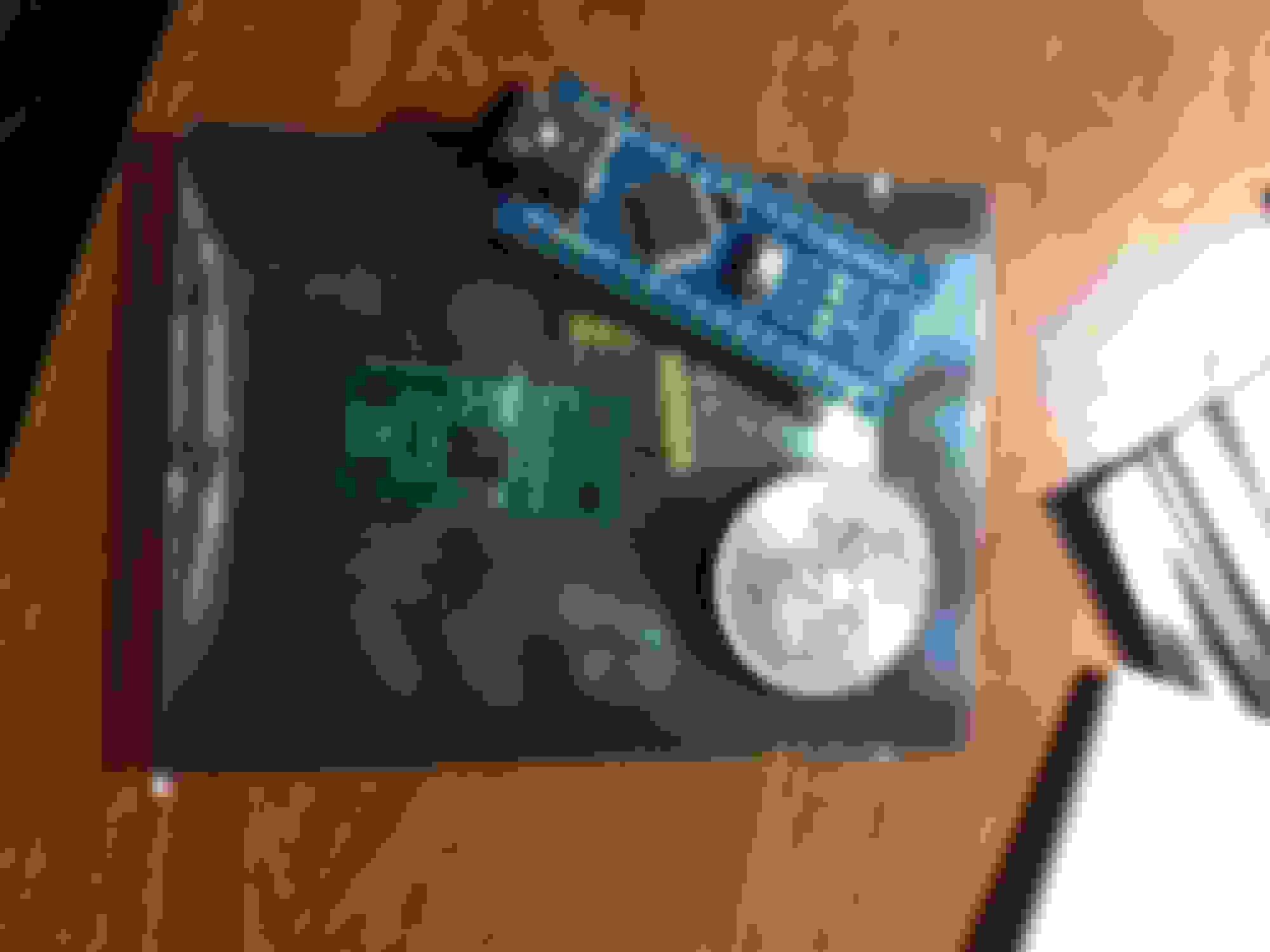
I'm pretty sure I can do the same with an Arduino and a digital potentiometer. For about $20. I've ordered the Arduino all of my other ones are currently in projects.
Re: Calculation needed from you useful electrical wizards
I just replaced the two gauge resistors wit 0-1k pots and found no combination where a 40-240ohm signal will work. I can get one end or the other but not both. Also the gauge seemed to be very lazy (not that it needs to be fast but just an observation). I was going to suggest a signal conditioner and saw Aviators post which should work.
Re: Calculation needed from you useful electrical wizards
Thought, it's works as a voltage divider? Can you use a pick up resistor and a diode to prevent it from sending current to the sender. So that 40ohms still gives you the voltage of 0ohm under orginal setup?
Re: Calculation needed from you useful electrical wizards
I forgot that I had an extra set of gages so I pulled the fuel gage and measured out a few things (picture below). Can you speculate how the coils are wired in that circuit? I'm guessing it has to be in series with the resistors.
PaulyC, nice work! I think you just squashed the idea that resistors can be changed for compatibility with 4th gen sender. Maybe the team will now come up with an alternative that does work.
Re: Calculation needed from you useful electrical wizards
PaulyC,
Can you dial in 43 Ohm and 250 Ohm gage resistors and tell me how the fuel gage acts when sweeping through the 40-250 Ohm range a 4th gen tank sender? Specifically, what are the gage readings when sender is at the 1/4, 1/2, 3/4, and full points? (93 , 145 , 198 , 240 Ohms)
I am still wondering if I have a lot of resistance in wiring between gage and tank. Your answers will help me figure that out. Thanks!
Re: Calculation needed from you useful electrical wizards
So I worked on this some more this afternoon, again focusing on the camaro gauge and believe I can make the gauge work acceptably with the 4th gen sender now over the 40 ohm empty to 250 ohm full range
- First thing I did was to validate that if I lowered the external resistance relative to the full sender resistance of 250 ohm (ie make the external resistance smaller than 250 ohm vs equal) I can "overdrive" the needle position relative to full and give myself some additional sweep. I wanted to do this do to what I was going to do next
- Next I decided that since empty with the 4th gen sender is 40 ohms vs zero ohms and knowing I didn't have with the present circuit a way of electrically only resolving that I decided to mechanically remove the needle. I used a plastic interior panel removal tool I had and it "popped" off fairly easily although it is a little bit of force, not terrible but also it doesn't just slide right off. but it came off without damage
- I then proceeded to experiment a little bit to get the best position of empty to full using the freedom to mechanically position the needle and adjust the external resistor
- In the end I ended up actually with my 220 ohm resistor I had pulled from my pile (although I did use a pot to move around and actually came almost right to 220 using it!) and mechanically positioned the needle with that resistance to be on empty with the sender at 40 ohms.
This resulted in a pretty good gauge range. At 40 ohm it is on empty, and at 250 ohm it is near full... I could make it exactly full, but do to the fact that I had to offset the gauge circuit/mechanics I needed to give a little windage at full so that at around half the sender range (~145 ohm) the gauge reads about 5/8... Anyways to me I now have the gauge more than accurate enough for its purpose and I didn't need to modify the tank sender or introduce a new circuit. If you are a stickler you are going to have to either go back to in tank sender mod or use the suggested external circuit box to interpolate the signal
I haven't yet looked at the firebird circuit but likely again using both a mechanical adjustment and resistor probably could get it to be reasonable as well
Last edited by alan91z28; Dec 9, 2018 at 03:37 PM.
Here is another version they sell. The instructions are there too.
I suppose that the easiest place to tie into the fuel gauge wires is where the wires drop from the dash down to the door sill on the way to the back of the car.
Re: Calculation needed from you useful electrical wizards
The eBay one only maps 3 ponts. It might be good enough but I would want the full sweep. The best thing about the converter box is everything is replaceable.
People also use Arduino boards to drive car cluster for racing game simulators. I've seen video of people driving BMW clusters tach and speedometer with them. So you could also use one to calibrate the lag at high rpm of the factory tach.
Re: Calculation needed from you useful electrical wizards
Originally Posted by QwkTrip
PaulyC,
Can you dial in 43 Ohm and 250 Ohm gage resistors and tell me how the fuel gage acts when sweeping through the 40-250 Ohm range a 4th gen tank sender? Specifically, what are the gage readings when sender is at the 1/4, 1/2, 3/4, and full points? (93 , 145 , 198 , 240 Ohms)
I am still wondering if I have a lot of resistance in wiring between gage and tank. Your answers will help me figure that out. Thanks!
Re: Calculation needed from you useful electrical wizards
Originally Posted by alan91z28
I then proceeded to experiment a little bit to get the best position of empty to full using the freedom to mechanically position the needle and adjust the external resistor
You got me curious so I hooked up a little Duracell 9V battery to my Firebird fuel gage and ran the needle from empty to full. The needle hits the mechanical stops at about 1/8 tank beyond E and F, so there is some wriggle room to clock the needle position toward E and still be able to indicate a full tank. It also seems the armature is willing to move a bit past the stops if allowed (stops are built into the needle). So that gives even more wriggle room to clock the needle toward E and maybe still be able to hit F mark.
Picture of Firebird gage at E and F mechanical stops.
Re: Calculation needed from you useful electrical wizards
yes I would think that you could get it to work reasonably well, just like I demonstrated with the Camaro gauge... the adapter boxes are nice, but I just hate to add additional gadgets if I don't have to for long term durability and ease of maintaining operability over the long haul...
I have had to remove firebird speed needles as currently working on replacement odometer gear with Odometer Gears. those needles come off pretty easy, I haven't tried a fuel gauge one yet, but the Camaro one wasn't bad. when I get a chance I will try and take apart one of my spare firebird gauges to look at it, my guess is changing the one resistor and moving the needle position will work, but will have to try it
Re: Calculation needed from you useful electrical wizards
Yes, it was easy to pop off the needle. I couldn't get a good enough grip with my fingers to pull it off, but it came off easy by supporting the board with my fingers and pulling the motor straight out the back. The board is ample rigid in that area to not crack. The armature shaft is a tiny little thing. I think you're less likely to bend it pulling on the motor than trying to pry off the needle from the motor.
Re: Calculation needed from you useful electrical wizards
Ok, I tried a 47ohm and 220ohm on the gauge (I didn't have enough pots to run one on everything so I used resistors) and it makes the whole thing really not responsive and I got the same reading with different resistances on the tank resistor. Seems like the factory values are tuned with the gauge coils or something. I don't think it would be reliable this way.
Next I installed a 150ohm resistor in parallel with the tank unit. With the tank at 40ohms I set the pointer to E and increased the resistance and read the following:
40 = E
71 = 1/4
102 = 1/2
193 = 3/4
250 ends up 2 ticks over 3/4
If you do the math on the 150ohm it basically drops the resistance of the circuit when the tank is at 250 to approx. 90 (the gauge F value). This makes the max reading the difference between 0 (gauge E) and 37 (tank 40ohms and the 150ohm paralleled) or so it equals when the tank is empty at 40ohms. If you don't set the pointer to E at 40ohms this will read F when tank is at 250ohms but be just under 1/4 at tank 40ohms. I hope that makes sense, its simpler than it sounds.
Possible a higher resistance would get you closer to F but if it were me I am more worried about E being correct than F. I repeated this test with a 100ohm but it just narrowed the resolution and topped out at one tick over 3/4.
Re: Calculation needed from you useful electrical wizards
Thank you! Well, it seems we've sliced and diced this resistor thing any way we can and conclusion is the 3rd gen gage just won't operate properly with a 4th gen sender. The culprit is not being able to achieve 0 Ohm resistance from the sender at empty. Seems the coils in the gage are tuned around that value.
Just for reference, the gage in my car will move between 1/4 to F with the 4th gen sender, and gage modified to have 43 and 250 Ohm resistors. The needle is on the F mark when tank is full. The gage spends a lot of time between F and 3/4 as the fuel is being used. Once the needle gets to 1/2 it will begin to drop pretty darn fast to 1/4 tank where the car will run out of fuel at any moment.
Aviator857, I think your ideas are next on the agenda!
Re: Calculation needed from you useful electrical wizards
Originally Posted by PaulyC
Ok, I tried a 47ohm and 220ohm on the gauge (I didn't have enough pots to run one on everything so I used resistors) and it makes the whole thing really not responsive and I got the same reading with different resistances on the tank resistor. Seems like the factory values are tuned with the gauge coils or something. I don't think it would be reliable this way.
Next I installed a 150ohm resistor in parallel with the tank unit. With the tank at 40ohms I set the pointer to E and increased the resistance and read the following:
40 = E
71 = 1/4
102 = 1/2
193 = 3/4
250 ends up 2 ticks over 3/4
If you do the math on the 150ohm it basically drops the resistance of the circuit when the tank is at 250 to approx. 90 (the gauge F value). This makes the max reading the difference between 0 (gauge E) and 37 (tank 40ohms and the 150ohm paralleled) or so it equals when the tank is empty at 40ohms. If you don't set the pointer to E at 40ohms this will read F when tank is at 250ohms but be just under 1/4 at tank 40ohms. I hope that makes sense, its simpler than it sounds.
Possible a higher resistance would get you closer to F but if it were me I am more worried about E being correct than F. I repeated this test with a 100ohm but it just narrowed the resolution and topped out at one tick over 3/4.
yes pretty much that empty having the 40 ohm offset vs original being zero ends up making it a compromise as i found on the camaro gauge. you can get it reasonable but not exact. i agree with you on having the lower end be correct... i am also going to try one of the adjustment boxes as am interested in seeing how they work as well. good job looking into this!
Re: Calculation needed from you useful electrical wizards
FWIW the speedway adapter box has a max ohm of 240 according to their videos on youtube. http://www.marshallinstruments.com/products/9230.cfm seems to meet the bill (this is the one on ebay, I've emailed them to find out if it does the full sweep or just the 4 points)
the classic instruments one seems pretty solid and has the 40-250 ohm and 0-90ohm settings built in so less hassle.
Also one issue is Delphi redesigned the 4th gen pump assembly so the grand prix sender board no longer fits on it.
Re: Calculation needed from you useful electrical wizards
I ordered the one from marshallinstruments off ebay https://www.ebay.com/itm/372485808354 after emailing them they confirmed it does a linear sweep of the gauge so it should move consistently with the fuel level, they way their website was worded I was afraid it only mapped the E, 1/2, F levels to the gauge.
I'm also going to do the Arduino/digital pot just so I can do the write up... though the main reason I ordered an arduino is that I want to build a buffer to my tach so I can take the output from the PCU and fudge it a little to the tach so its not 2-300 rpm low above 4k RPMs. I bought a few of them. Basically taking this idea from the video game people
Re: Calculation needed from you useful electrical wizards
I got my electronics training in the 80s, so to me that Arduino is cheating. But I will admit - it's cool.
I guess this another area I have become a dinosaur.
Re: Calculation needed from you useful electrical wizards
I did buy http://www.marshallinstruments.com/products/9230.cfm and it does work but its slow to respond, and reads high on the down sweep, that is each ohm increase the gauge reads right, but each ohm decrease it doesn't read as accurately. It also makes a high pitch wine.
The Arduino works, but I think I may have decided ultimately I am going to build new guts for my fuel gauge using the stepper motors that newer clusters use. It should in the end be a direct replacement gauge. With one glitch the needle pin is a little to large for the factory needles so you would need to drill out the needle some.
http://www.mikesflightdeck.com/instr...struments.html will tell you more than you want to know about how the factory gauge works. As Qwktrip said above the resistors doesn't have a large effect you would have to do new winding in the air core to get the right balance at the different ohms.
I also see that 19121306 will work on the new style pump housing but I can't find out if its 0-90 ohm or the 40-250 ohm
Re: Calculation needed from you useful electrical wizards
Hey @Aviator857 - I am doing a '99 LS1 tank swap into my '91 Z28 and your solution is the closest and cleanest I have seen to plug-and-play - which is what I'm going for. Would you be willing to share your code/Arduino sketch? I have a background in software and DIY electronics and would like to think I'm more than capable of finishing this off. Thank you


 f:0
f:0