
9 Second project coming together.....


Thread Starter
Member
Joined: Jun 2002
Posts: 268
Likes: 0
From: Midlothian, Texas
9 Second project coming together.....
Alright guys. I've been working on this project for the past two years and have a little free time to re-cap where I started from and where I am at now. I've been getting quite a few questions about the setup and I am starting this thread to address them. The plan has been to build a car that can repeatedly make low 9 sec passes. Here's the info:
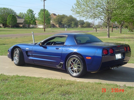
1992 Heritage Edition Z28
415 cid
Dart block
Lunati forged crank
Lunati rods
JE pistons
Cam Motion solid roller blower grind
Jesel belt drive
T&D shaft rockers
AFR 227 cylinder heads
Hogan's sheet metal EFI intake
FAST 86 lb/hr injectors
FAST XFI engine management with all the bells and whistles
MSD 10-Plus ignition
F1R Procharger with cog drive
Air-to-Water intercooler
Custom heat exchanger
2-Stage NOS system (#1 Dry & #2 Direct port NOS fogger)
Manual Brake conversion (thanks Ed Quay)
Manual steering conversion (thanks S10)
Full roll cage.
Last edited by Kendol; Jul 7, 2010 at 01:54 PM.


Thread Starter
Member
Joined: Jun 2002
Posts: 268
Likes: 0
From: Midlothian, Texas
Re: 9 Second project coming together.....
Some pics of the engine:
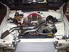
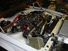
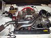
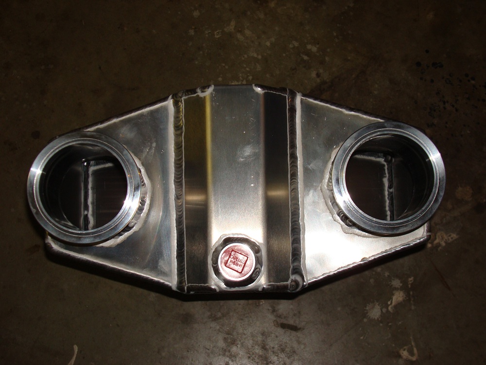
I wanted to keep the charge air tube as short and straight as possible.


I wanted to keep the charge air tube as short and straight as possible.
Last edited by Kendol; Jul 7, 2010 at 02:31 PM.


Trending Topics


Joined: Sep 2003
Posts: 25,895
Likes: 429
From: Pittsburgh PA
Car: 89 Iroc-z
Engine: 555 BBC Turbo
Transmission: TH400
Axle/Gears: MWC 9� 3.00
Re: 9 Second project coming together.....
Wow. Impressive. Shouldnt have a problem with 1000 hp and low 9's with that setup. Even off the footbrake.
Thread Starter
Member
Joined: Jun 2002
Posts: 268
Likes: 0
From: Midlothian, Texas
Re: 9 Second project coming together.....
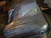
Thought I would post some pics of the fuel tank mods I did. I left the original intank pump in place and use it to feed the direct port NOS system off its' own fuel pressure regulator.


Thread Starter
Member
Joined: Jun 2002
Posts: 268
Likes: 0
From: Midlothian, Texas
Re: 9 Second project coming together.....
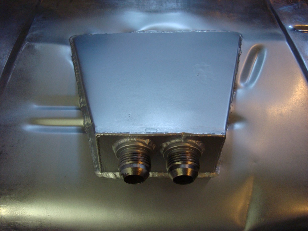
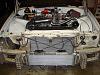
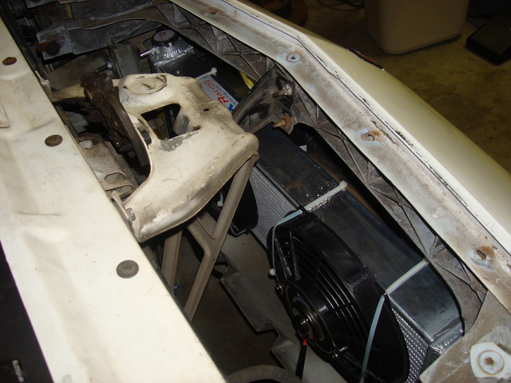
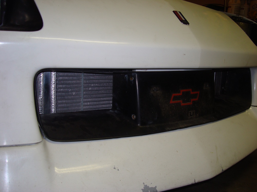
Even though I will be using a 10 gallon water tank mounted in the rear hatch well filled with ice, I also added a heat exchanger to help keep the water temps in check for street use. I mounted the heat exchanger in the front bumper and intend to use air through the bumper opening to provide cooling air for the radiator.


Thread Starter
Member
Joined: Jun 2002
Posts: 268
Likes: 0
From: Midlothian, Texas
Re: 9 Second project coming together.....
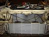
I mounting my transcooler today. I found a way to place it under the intercooler on the passenger side of the front inner fender. I think the additional air flow over the intercooler case should help prevent heat saturation. It has an electric fan that will be controlled by a thermostatic switch. I'll take some pics this afternoon and post them when I am done.


TGO Supporter


Joined: Jul 2001
Posts: 4,991
Likes: 1
From: Cheyenne, Wyoming
Car: 1992 B4C 1LE
Engine: Proaction 412, Accel singleplane
Transmission: built 700R4 w/custom converter
Axle/Gears: stock w/later 4th gen torsen pos
Re: 9 Second project coming together.....
I really do love the work and your car. It seems like you have refused to cut a lot of corners. That intake must have been pure rape on your finances.
It makes me think of my own car:
http://www.outlawperformance.com/ima...stuff/progress
Do you drive this around or is it pure track?
Which tires/wheels are you running?
Have you considered E85?
Did you do the whole acid bath and tank coating stuff after welding the fuel tank?
Which trans are you running?
which rear end?
what suspension?
I see you and my friend ran the same kind of coolant hose for the liquid to air. He runs no exchanger, just coolant and ice. It seems low tech, but trust me, it is simple tech. It has its own thread here:
https://www.thirdgen.org/forums/powe...o-350-ls1.html
Last edited by B4Ctom1; Jul 6, 2010 at 04:27 PM.

Joined: Sep 2003
Posts: 25,895
Likes: 429
From: Pittsburgh PA
Car: 89 Iroc-z
Engine: 555 BBC Turbo
Transmission: TH400
Axle/Gears: MWC 9� 3.00
Re: 9 Second project coming together.....
I wouldnt mind trying one of these air to water deals. Looks fantastic. I would need two smaller units up under the nose somewhere, one for each turbo but looks like I'd have alot to gain with a setup like that. Ice water would really help things out but for general street driving, i would think water would reach ambient and be no more effective than air to air in the end. Maybe just alittle bit more since liquid transfer more heat.
Thread Starter
Member
Joined: Jun 2002
Posts: 268
Likes: 0
From: Midlothian, Texas
Re: 9 Second project coming together.....
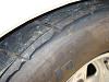
The goal was to build something to drive around on the streets when I get bored with the Z06. I guess, its mostly going to be a strip car but it WILL see some street time. I'm running Crager drag stars in back (15x10) and up front (15x3.5). I'm currently running 275x60R15 BFG drag radials out back, but found a problem this morning with them rubbing the fender lip under hard acceleration. Not sure how I'm going to fix this???? I checked the rubber bumper (axle limiter) and its completely degraded on both sides. Replacing them may help limit the interference, but i'm afraid I may have to raise the rear suspension or go to a different tire. D@$@T! I am not a fan of alcohol and how tough it is on aluminum parts. With its stellar latent heat of vaporization it works great, but defeats the street car theme.
As far as the fuel tank goes, once we finished all the welding, we acid dipped the tank, pressure tested it 6 psi, and sprayed on a rust preventative coating. Please keep in mind though, I started with a new tank and refused to weld on a used one. With the right saftey precautions in place (i.e. backfilling with Argon or another inert gas) you MIGHT be OK, but I wasn't willing to take the chance.
Transmission is a ProBuilt 700R4 and a 3200rpm Precision stall converter. I know it wont last under the power levels but, I can do most of my tuning with it. So far, its heldup fine. I'm sure its on borrowed time though. Don't know if it was worth all the trouble of fabbing a kickdown cable bracket on the Accufab throttle body though. Either way, I had to do it to control the 700R4.
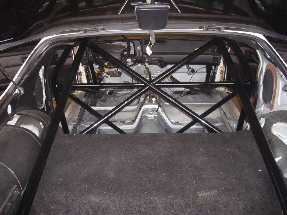
Suspension is mostly stock. I am using new poly bushings but everything else is as the factory made it. It will be fun to see which parts break first. I find that one of the best things about drag racing, you always find the weakest link. I stiffened the chassis a great deal with fabricated subframes and a 12 pt cage. Instead of welding the cage to weak sheet metal, I welded it directly to the subframes.
The rear is a stock 9-bolt Ausi unit, but a Fab9 is in the works.


As far as the fuel tank goes, once we finished all the welding, we acid dipped the tank, pressure tested it 6 psi, and sprayed on a rust preventative coating. Please keep in mind though, I started with a new tank and refused to weld on a used one. With the right saftey precautions in place (i.e. backfilling with Argon or another inert gas) you MIGHT be OK, but I wasn't willing to take the chance.
Transmission is a ProBuilt 700R4 and a 3200rpm Precision stall converter. I know it wont last under the power levels but, I can do most of my tuning with it. So far, its heldup fine. I'm sure its on borrowed time though. Don't know if it was worth all the trouble of fabbing a kickdown cable bracket on the Accufab throttle body though. Either way, I had to do it to control the 700R4.
Suspension is mostly stock. I am using new poly bushings but everything else is as the factory made it. It will be fun to see which parts break first. I find that one of the best things about drag racing, you always find the weakest link. I stiffened the chassis a great deal with fabricated subframes and a 12 pt cage. Instead of welding the cage to weak sheet metal, I welded it directly to the subframes.
The rear is a stock 9-bolt Ausi unit, but a Fab9 is in the works.
Last edited by Kendol; Jul 7, 2010 at 12:57 PM.

Joined: May 2008
Posts: 867
Likes: 1
From: pawtucket RI
Car: 1986 iroc
Engine: alum. head 350 supercharged
Transmission: 6speed
Axle/Gears: ford 9in 3.90 35 spline moser axles
Re: 9 Second project coming together.....
cars looking SICK man 
TGO Supporter
Joined: Jul 2001
Posts: 4,991
Likes: 1
From: Cheyenne, Wyoming
Car: 1992 B4C 1LE
Engine: Proaction 412, Accel singleplane
Transmission: built 700R4 w/custom converter
Axle/Gears: stock w/later 4th gen torsen pos
Re: 9 Second project coming together.....
The goal was to build something to drive around on the streets when I get bored with the Z06. I guess, its mostly going to be a strip car but it WILL see some street time. I'm running Crager drag stars in back (15x10) and up front (15x3.5). I'm currently running 275x60R15 BFG drag radials out back, but found a problem this morning with them rubbing the fender lip under hard acceleration. Not sure how I'm going to fix this???? I checked the rubber bumper (axle limiter) and its completely degraded on both sides. Replacing them may help limit the interference, but i'm afraid I may have to raise the rear suspension or go to a different tire. D@$@T! I am not a fan of alcohol and how tough it is on aluminum parts. With its stellar latent heat of vaporization it works great, but defeats the street car theme.
Attachment 202467
Attachment 202468
Attachment 202469
As far as the fuel tank goes, once we finished all the welding, we acid dipped the tank, pressure tested it 6 psi, and sprayed on a rust preventative coating. Please keep in mind though, I started with a new tank and refused to weld on a used one. With the right saftey precautions in place (i.e. backfilling with Argon or another inert gas) you MIGHT be OK, but I wasn't willing to take the chance.
Transmission is a ProBuilt 700R4 and a 3200rpm Precision stall converter. I know it wont last under the power levels but, I can most of my tuning with it. So far, its heldup fine. I'm sure its on borrowed time though. Don't know if it was worth all the trouble of fabbing a kickdown cable bracket on the Accufab throttle body though. Either way, I had to do it to control the 700R4.
Suspension is mostly stock. I am using new poly bushings but everything else is as the factory made it. It will be fun to see which parts break first. I find that one of the best things about drag racing, you always find the weakest link. I stiffened the chassis a great deal with fabricated subframes and a 12 pt cage. Instead of welding the cage to weak sheet metal, I welded it directly to the subframes.
The rear is a stock 9" Ausi unit, but a Fab9 is in the works.
list of E85 equipped Texas gas stations
http://www.seco.cpa.state.tx.us/zzz_...l-stations.pdf
There are plenty of E85 stations in our area too.
As far as how hard alcohol is on parts, straight alcohol is harder than E85, and even then a lot of the damage is related to people who don't take simple precautions. Hell if thousands if not millions of stock flex fuel vehicles running mass produced factory parts can run it without issue, then by god my vehicle with much better parts can.
I agree with you about the drivetrain, I doubt at your power levels that 700 trans or tiny 9 bolt Aussie will hold up for long. The rear is more valuable as a collectors item than a race piece.
Thread Starter
Member
Joined: Jun 2002
Posts: 268
Likes: 0
From: Midlothian, Texas
Re: 9 Second project coming together.....
Sorry. Had a brain fart. I was thinking straight methanol. As far as E85, there really isn't a need in my application--I'm using an alky injection kit from snow performance.
Joined: May 2008
Posts: 867
Likes: 1
From: pawtucket RI
Car: 1986 iroc
Engine: alum. head 350 supercharged
Transmission: 6speed
Axle/Gears: ford 9in 3.90 35 spline moser axles
Re: 9 Second project coming together.....
doesn't the battery have to be in asealed box or is that just for the acid batteries?
Joined: Sep 2003
Posts: 25,895
Likes: 429
From: Pittsburgh PA
Car: 89 Iroc-z
Engine: 555 BBC Turbo
Transmission: TH400
Axle/Gears: MWC 9� 3.00
Re: 9 Second project coming together.....
Curious as to how much power you are attempting to make before spraying it. I would think you could make over 800whp on straight pump gas alone on medium boost before the need to meth inject it. Thats a lower 9 second car for sure.
Thread Starter
Member
Joined: Jun 2002
Posts: 268
Likes: 0
From: Midlothian, Texas
Re: 9 Second project coming together.....
Tom86Iroc- The battery is sitting in the rear hatch area for ease of access. I actually fabbed a mount for it to reside in the passenger side rear fender well (where the spare tire used to be). Unfortunately, as I work on the car and I drain the battery, I have to remove that rear plastic cover to charge it.
You bring up a good question though. Optimas are still acid batteries--don't let anyone lie to you and say they're not. As for needing a sealed box, the rule book says I do, but I know of a lot of guys getting away with it mounted in the spare tire area. I understand the rule, in that, if fumes start escaping from the battery they don't want them to fill the driver's compartment. Anyone else have input on this?
You bring up a good question though. Optimas are still acid batteries--don't let anyone lie to you and say they're not. As for needing a sealed box, the rule book says I do, but I know of a lot of guys getting away with it mounted in the spare tire area. I understand the rule, in that, if fumes start escaping from the battery they don't want them to fill the driver's compartment. Anyone else have input on this?
Supreme Member
iTrader: (8)
Joined: Jul 2001
Posts: 3,204
Likes: 7
From: New Boston, IL, USA
Car: '90 Formula 350
Engine: 383 SBC
Transmission: ProBuilt S/S 700-R4 & ACT 9" Stall
Axle/Gears: 10 bolt 3.23
Re: 9 Second project coming together.....
I've ran a yellow top in the backseat for acouple thousand miles on street use. I've never seen any leakage. Obviously your car is going to see a lot of track use so needs to be up to specs, depending on how picky the techs are.
http://www.nhraonline.com/contacts/tech_faq.html
http://www.nhraonline.com/contacts/tech_faq.html
I have a street car that I occasionally run at the strip. I've relocated the battery to the rear. What else do I need?
Any car with a relocated battery must be equipped with a master electrical cutoff, capable of stopping all electrical functions including ignition (must shut the engine off, as well as fuel pumps, etc.). The switch must be located on the rear of the vehicle, with the "off" position clearly marked. If the switch is of a "push / pull" type, then "push" must be the motion that shuts off the switch, and plastic or "keyed" typed switches are prohibited. Also, the battery must be completely sealed from the driver and/or driver compartment. This means a metal bulkhead must separate the trunk from the driver compartment, or the battery must be located in a sealed, metal box constructed of minimum .024 inch steel or .032 inch aluminum, or in an NHRA accepted plastic box. In cars with a conventional trunk, metal can simply be installed behind the rear seat and under the package tray to effectively seal the battery off from the driver. In a hatchback type vehicle the battery box is usually the easiest solution, since the alternative is to fabricate a bulkhead which seals to the hatch when closed. At present, Moroso is the only company which offers an NHRA accepted plastic battery box, part number 74050.
Any car with a relocated battery must be equipped with a master electrical cutoff, capable of stopping all electrical functions including ignition (must shut the engine off, as well as fuel pumps, etc.). The switch must be located on the rear of the vehicle, with the "off" position clearly marked. If the switch is of a "push / pull" type, then "push" must be the motion that shuts off the switch, and plastic or "keyed" typed switches are prohibited. Also, the battery must be completely sealed from the driver and/or driver compartment. This means a metal bulkhead must separate the trunk from the driver compartment, or the battery must be located in a sealed, metal box constructed of minimum .024 inch steel or .032 inch aluminum, or in an NHRA accepted plastic box. In cars with a conventional trunk, metal can simply be installed behind the rear seat and under the package tray to effectively seal the battery off from the driver. In a hatchback type vehicle the battery box is usually the easiest solution, since the alternative is to fabricate a bulkhead which seals to the hatch when closed. At present, Moroso is the only company which offers an NHRA accepted plastic battery box, part number 74050.
Thread Starter
Member
Joined: Jun 2002
Posts: 268
Likes: 0
From: Midlothian, Texas
Re: 9 Second project coming together.....
I've actually overcharged one before, and it filled the shop up with sulfur fumes. I know there is a risk and if it doesn't conform to the rules I will have to change it. No biggy, I'll just buy the Moroso box and modify my existing bracket to fit.
Thread Starter
Member
Joined: Jun 2002
Posts: 268
Likes: 0
From: Midlothian, Texas
Re: 9 Second project coming together.....
Fireturd350--
Thanks for posting that NHRA rule recap. It brings up another more serious question though.... The emergency battery disconnect switch should be able to kill the engine in an emergency right? That means the alternator charging wire has to be on the battery side of the disconnect switch! If the car is running when the switch is thrown, the alternator will continue to power the cars electonics and prevent it from dying. This is a huge problem for me as I just went out and checked it and my car will not stop. S@$t! guess that means I'll have to run the alternator charging wire all the way to the back of the vehicle.
Thanks for posting that NHRA rule recap. It brings up another more serious question though.... The emergency battery disconnect switch should be able to kill the engine in an emergency right? That means the alternator charging wire has to be on the battery side of the disconnect switch! If the car is running when the switch is thrown, the alternator will continue to power the cars electonics and prevent it from dying. This is a huge problem for me as I just went out and checked it and my car will not stop. S@$t! guess that means I'll have to run the alternator charging wire all the way to the back of the vehicle.
Joined: Sep 2003
Posts: 25,895
Likes: 429
From: Pittsburgh PA
Car: 89 Iroc-z
Engine: 555 BBC Turbo
Transmission: TH400
Axle/Gears: MWC 9� 3.00
Re: 9 Second project coming together.....
I have the plastic battery box on my car mounted on the passenger side frame rail. (that big flat spot between trunk floor and the spare tire well.) Bolted to the floor pan but I think its supposed to be to the frame rail. I just welded nuts to the floor pan and used that as the hold down. NEVER had a problem with tech inspections this way.
Alternator charge wire goes back to the battery. Battery positive to the switch. then switch to starter. If you kill the switch while running the alternator will not beable to back feed the motor with this configuration. So yes, alternator to battery side of switch.
Alternator charge wire goes back to the battery. Battery positive to the switch. then switch to starter. If you kill the switch while running the alternator will not beable to back feed the motor with this configuration. So yes, alternator to battery side of switch.
Thread Starter
Member
Joined: Jun 2002
Posts: 268
Likes: 0
From: Midlothian, Texas
Re: 9 Second project coming together.....
Orr89RocZ--
The duel stage NOS system will be used as a back up. I've had blower belts break or stretch in competition and, typically without a replacement, the race day is over. I thought a good way to stay competitive would be to have a backup NOS system that can produce as much power alone as the blower did. My 1st stage is a 150hp dry shot with the XFI handling the fuel enrichment and timing retard. The 2nd stage is a 300hp wet (direct port) shot with the XFI only handling the timing retard and activation.
As far as using them inconjunction with the blower, though tempting, I doubt it will ever happen. I have been contemplating a dry 75hp shot to help cool the air charge, but it will be illegal in most competitions that only allow for one power adder. Last year one of my buddies did this and it worked great. We saw that the effects were almost double (i.e. 75hp equated more to 150hp) when he was spraying his blown Corvette. Besides, if I ever get desperate to win a race or just want to see how much power the dart block can handle, I can always run them full tilt with the blower.
Thread Starter
Member
Joined: Jun 2002
Posts: 268
Likes: 0
From: Midlothian, Texas
Re: 9 Second project coming together.....
The primary reason I don't want to rerun the alternator charging wire is that I am using a 0-Awg charging wire now and the additional distance will cause me to go up one wire size (00-Awg) to combat voltage drop. Not to mention I will need to figure out a way to get the charging wire through the firewall and back to the battey. This, in turn, means I will have to pull the carpet as I run it through the interior of the car. Da@@$t!!!!!!!!
Last edited by Kendol; Jul 7, 2010 at 12:49 PM.
Joined: Sep 2003
Posts: 25,895
Likes: 429
From: Pittsburgh PA
Car: 89 Iroc-z
Engine: 555 BBC Turbo
Transmission: TH400
Axle/Gears: MWC 9� 3.00
Re: 9 Second project coming together.....
Thats a huge wire. My main feed line from battery box to motor is 0 AWG I think (whatever came with the kit) but my alternator feed wire is only 4 AWG. Much smaller. I never had charging problems until this year running stock alternator. this year i have a few more electric gauges, an electric water pump, and both fans are now on their own switches/relays so it sucks power. I think the alternator is going out anyway.
But before with the nitrous 383 i had, standard belt driven water pump, and only 1 fan on i had no problems.
I dont think you need that large of a charging wire.
But before with the nitrous 383 i had, standard belt driven water pump, and only 1 fan on i had no problems.
I dont think you need that large of a charging wire.
Thread Starter
Member
Joined: Jun 2002
Posts: 268
Likes: 0
From: Midlothian, Texas
Re: 9 Second project coming together.....
It might be worth pointing out all the electrical accessories I have:
2 - Primary cooling fans for the radiator
2 - Primary fans for the AWIC heat exchanger
1 - Primary fan for the transcooler
2 - AeroMotive Eliminator fuel pumps
1 - Meziere electric water pump for the engine
1 - Meziere electric water pump for the AWIC tank
1 - FAST XFI
1 - MSD 10Plus ignition box
1 - ALky injection kit
2 - NOS stages
5 - accessory guages
1 - XFI touchscreen datalogger
& all the standard loads for lights, widshield wiper, and basic radio.
Last edited by Kendol; Jul 7, 2010 at 12:48 PM.
Senior Member
iTrader: (1)
Joined: Jun 2006
Posts: 999
Likes: 0
From: Iowa
Car: 1987 IROC
Engine: 350 vortec
Transmission: TH350 3500 stall
Axle/Gears: 3.73 10 bolt grenade
Re: 9 Second project coming together.....
i don't think i've ever heard of anyone using that large of alternator wire. 4GA should be plenty to carry all the current back to the battery. just think about a modern vehicle with multiple control modules and everything electronic, the wire is what like 12GA? maybe 10?
Thread Starter
Member
Joined: Jun 2002
Posts: 268
Likes: 0
From: Midlothian, Texas
Re: 9 Second project coming together.....
Let's do some math:
(12A continuous each) 2 - Primary cooling fans for the radiator
(8A continuous each) 2 - Primary fans for the AWIC heat exchanger
(6A continuous) 1 - Primary fan for the transcooler
(11A conituous each) 2 - AeroMotive Eliminator fuel pumps
(5A continuous) 1 - Meziere electric water pump for the engine
(5A continuous) 1 - Meziere electric water pump for the AWIC tank
(6A continuous, but more if I use PWM outputs)1 - FAST XFI
(3A @ idle, 16A @ 6000 rpm) 1 - MSD 10Plus ignition box
(4A when activated) 1 - ALky injection kit
(5A for 1st, 18A for 2nd) 2 - NOS stages
(2A continuous) 5 - accessory guages
(3A but more if I use PWM outputs) 1 - XFI touchscreen datalogger
(15-20A at night) & all the standard loads for lights, widshield wiper, and basic radio.
That's over 100A with all the accessories running. When sizing wire you should always go for worst case. Now, all the accessories may not be running all the time, but if 75% are then I am still over 75A. If you look up a wire ampacity chart you will see a 12AWG wire is only good for 20A continuous, 30A intermittant rating. A 0-AWG wire can handle 150A continuous (both assume copper conductor). A 4AWG wire can handle 70A continuous and 85A intermittant. Either way, I would rather run a wire slightly larger than what I need than one too small.
Thread Starter
Member
Joined: Jun 2002
Posts: 268
Likes: 0
From: Midlothian, Texas
Re: 9 Second project coming together.....
Another thing worth noting is that I am using a 140A alternator. I have proven it can run the car with all of its loads even with the battery disconnected. I will use my amp clamp and measure the load placed on the alternator when I do this. This will be a real world test to see how much of a combined drain there is on the battery. Another thing worth considering is that the longer the cable, the greater the voltage drop. The easiest way to offset this is to go up in wire size. I have a 15'+ run back to the battery in the trunk.

Supreme Member
iTrader: (1)
Joined: Jan 2002
Posts: 4,432
Likes: 1
From: garage
Engine: 3xx ci tubo
Transmission: 4L60E & 4L80E
Re: 9 Second project coming together.....
Nice build.
#2 copper would have easily met the requirements. #0 is way overkill but doesn't hurt anything. It is just much larger and harder to work with.
What did you upgrade the alternator to to put out the amps you need? Is it a AD144 150amp model? They work nice and make a great stick welder power source too.
Supreme Member
iTrader: (1)
Joined: Jan 2002
Posts: 4,432
Likes: 1
From: garage
Engine: 3xx ci tubo
Transmission: 4L60E & 4L80E
Re: 9 Second project coming together.....
Another thing worth noting is that I am using a 140A alternator. I have proven it can run the car with all of its loads even with the battery disconnected. I will use my amp clamp and measure the load placed on the alternator when I do this. This will be a real world test to see how much of a combined drain there is on the battery. Another thing worth considering is that the longer the cable, the greater the voltage drop. The easiest way to offset this is to go up in wire size. I have a 15'+ run back to the battery in the trunk.
Even at 15 feet the #2 copper is enough.
EDIT: It also sounds like you correctly wired in the battery disconnect switch with the alternator. Most people hack it and get random run-on with the switch.
Last edited by junkcltr; Jul 7, 2010 at 01:39 PM.
Thread Starter
Member
Joined: Jun 2002
Posts: 268
Likes: 0
From: Midlothian, Texas
Re: 9 Second project coming together.....
junkcltr--
Good point about the DC output ripple. I've never looked at the output of an alternator directly with an o-scope, but I'm sure the rectifier bridge isn't lab quality.
Here is a shot of the cable I am running now:
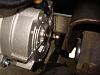
The alternator is a satin finish power master.
Good point about the DC output ripple. I've never looked at the output of an alternator directly with an o-scope, but I'm sure the rectifier bridge isn't lab quality.
Here is a shot of the cable I am running now:

The alternator is a satin finish power master.
Thread Starter
Member
Joined: Jun 2002
Posts: 268
Likes: 0
From: Midlothian, Texas
Re: 9 Second project coming together.....
I've just been burned too bad with my other thirdgen 89GTA. It has always had charging system issues even when I replaced the alternator with the same 140A PowerMaster unit and used a Yellow top Optima battery. I've checked all the main battery connections and wires, starter connections and wires, and I can't get the charging system to keep up (i.e. battery voltage is <12.2 V at idle, sometimes at night with the AC on <11.8V). I don't have underdrive pulleys, so that isn't the problem. With the charging system I have on my Z28, It works flawlessly. It holds 13.3V even when the car is idling at 900rpm and all the lights, fans, and electronics are on. I like it the way it is now and don't want a repeat of the problems I have with my 89GTA.
Supreme Member
iTrader: (1)
Joined: Jan 2002
Posts: 4,432
Likes: 1
From: garage
Engine: 3xx ci tubo
Transmission: 4L60E & 4L80E
Re: 9 Second project coming together.....
The rectifier is just 6 diodes with no cap or resistors. The only thing that reduces ripple is the load and battery. If the load is higher then there is less ripple w/o the battery, but still a fair amount of ripple.
The #0 copper looks good. weldingsuppy.com carries various gauge and colors (red) at a decent price. Figured I would put that out there if you needed more in the future.
The other trick some play with is creating voltage drop for the sense wire in order to put the output of the alternator higher. Some rely on the factory v_drop so that the alt. lug is higher and then tie the fuel pump in there in order to increase the output.
Supreme Member
iTrader: (1)
Joined: Jan 2002
Posts: 4,432
Likes: 1
From: garage
Engine: 3xx ci tubo
Transmission: 4L60E & 4L80E
Re: 9 Second project coming together.....
I've just been burned too bad with my other thirdgen 89GTA. It has always had charging system issues even when I replaced the alternator with the same 140A PowerMaster unit and used a Yellow top Optima battery. I've checked all the main battery connections and wires, starter connections and wires, and I can't get the charging system to keep up (i.e. battery voltage is <12.2 V at idle, sometimes at night with the AC on <11.8V). I don't have underdrive pulleys, so that isn't the problem. With the charging system I have on my Z28, It works flawlessly. It holds 13.3V even when the car is idling at 900rpm and all the lights, fans, and electronics are on. I like it the way it is now and don't want a repeat of the problems I have with my 89GTA.
Is that a stock 140amp off of something, or did you put in bigger parts in your stock case?
Thread Starter
Member
Joined: Jun 2002
Posts: 268
Likes: 0
From: Midlothian, Texas
Re: 9 Second project coming together.....
I never really thought about playing with the sense wire to create an artificial voltage drop. Guess I could always tie in the in-line fuel pump B+ relay supply wire there to see if it helps. I have a sneaking suspicion though that there is something damaged in the factory wiring and I just can't bring myself to tear into it. It is a real PITA.
Joined: Sep 2003
Posts: 25,895
Likes: 429
From: Pittsburgh PA
Car: 89 Iroc-z
Engine: 555 BBC Turbo
Transmission: TH400
Axle/Gears: MWC 9� 3.00
Re: 9 Second project coming together.....
I'm going to buy that alternator for my car and give it a shot. i know I need more amps too. Now I'm kinda worried my 4G wire is too small but I dont have as many power accessories. I do not know the amp loads of all the accessories either so I cant calculate the load i would have. I have half the stuff you have so I dont think I'm over the limit with 4G wire. I do know when i turn on my secondary fan the voltage drops alot and almost stalls the car  Gotta look into my battery charging, I think the stock alternator is too weak.
Gotta look into my battery charging, I think the stock alternator is too weak. Thread Starter
Member
Joined: Jun 2002
Posts: 268
Likes: 0
From: Midlothian, Texas
Re: 9 Second project coming together.....
It might be worth noting before I used the 0-AWG wire I used the high current wire that came with the alternator. Mind you, it was only to do a brief run check before I finished all the wiring, but I DID notice a pretty healthy voltage drop when I turned on both of my electric fans. I wasn't really concerned though because I knew I was going to a much larger wire in the end. If I remember correctly it was either an 8-AWG or 4-AWG wire. It was finely stranded and was very flexible.
Thread Starter
Member
Joined: Jun 2002
Posts: 268
Likes: 0
From: Midlothian, Texas
Re: 9 Second project coming together.....
Thought you guys might be interested in test results I just obtained while running the car with the AWIC and water tank. My custom tank won't be here until Tuesday next week from Chiseled Performance. I have an old 3 gallon aluminum fuel cell I decided to plumb in temporarily just to see what kind of a temp reduction in air temps I would see.
As expected, running the car without running water through the AWIC resulted in very high MATs. I have a water temperature sensor mounted in the AWIC core and and additional air temp sensor mounted in the tube going to the AWIC. This gave me the opportunity to watch the air temps both pre and post the intercooler and the intercooler water temp.
It has been rather hot today (i.e. 95*-98*) so this will represent a typical summer day here in Texas. I ran the car until the coolant temp stabilized at 180*-185* and watched the air temps. The AWIC water temp stabilized at 90*-95*. With the car idling and supercharger picking up hot air off the headers, the pre-AWIC air temp was in the 175*-180* range and the post temperature was 110*-115*. Loading the car against the brake and building 5 psi of boost, I saw the pre-AWIC air temp jump to 275*-280* almost immediately. Interestingly, the post air temp slowly (and I mean slowly) rose to 140*-150*. After which, I allowed the car to go back to idle and the AWIC heat exchanger slowly (5 min) lowered the water IC water temp back down to 100*. I repeated this test three times and the results were the same. Needless to say, I was very impressed. Mind you, this was with a 3 gallon tank, water temp starting at ambient, and I still saw almost a 50% reduction in air temps at low boost levels. I'm convinced now I made the right decision.
My custom tank will be 10.5 gallons and I will use ice water for drag night. I should be able to obtain MATs well below ambient at extremely high boost levels. I can't wait to test this on the dyno.
Last edited by Kendol; Jul 7, 2010 at 05:02 PM.
Thread Starter
Member
Joined: Jun 2002
Posts: 268
Likes: 0
From: Midlothian, Texas
Re: 9 Second project coming together.....
Crunching the numbers:
Efficiency= (T2-T3)/(T2-T4)
T2 = blower outlet temp (280*)
T3 = Intercooler outlet temp (150*)
T4 = Intercooler water temp (125*)
E = (130)/(155) = 83.9%
That's pretty freaking effective. Mind you this was with ambient temperature water (i.e. with the water at a typical street cruise temp). Once I use ice water the gains will really be impressive. An efficiency of well over 100% will be obtainable. I can see drag racing on a 100* day with boost pressures well over 20 psi and the intake manifold temp only being 80 degrees. Hooray for technology. It may be more complicated than a typical AAIC to install, but it's much more effective. I am a believer.
Joined: Sep 2003
Posts: 25,895
Likes: 429
From: Pittsburgh PA
Car: 89 Iroc-z
Engine: 555 BBC Turbo
Transmission: TH400
Axle/Gears: MWC 9� 3.00
Re: 9 Second project coming together.....
SOme good results there. But at 20 psi the air temps are going to be hotter than the 280 you measured at just 5 psi. Even with ice water, will it come down that much? Still more effective than air to air.