When you click on links to various merchants on this site and make a purchase, this can result in this site earning a commission. Affiliate programs and affiliations include, but are not limited to, the eBay Partner Network.
Hi everyone I'm new here. I recently picked up an 84 camaro without an engine for $500 So it's going to turn into dr. Frankenstein's monster. Work as a welder/fabricator/machinist so I wanted a project car to go a little wild on. I don't want to BUY parts I want to MAKE parts because that's what I enjoy.
I have a L92/6l80E I'm going to stuff in it, which means fabricating some engine mounts, and that got me thinking why not just make a tubular K member? Then that got me looking at coilover conversions. Lots of people like them, some don't because it limits wheel fitment. Naturally as I tumbled down that rabbit hole, fabricating some suspension parts came to mind, moving points around to relieve some of the clearance issues, etc.
I'm not familiar with this platform or how it handles on the road though so I'm hoping that I can get some input from pro touring or track guys about good or common tweaks people do to their setup to get the best performance. I don't plan on doing hardcore racing with it but I figure while I'm at it, it couldn't hurt to correct some issues that a 30 year old design might have.
any suggestions from the guys out there that have experience on this platform? I can handle the design and fabrication no problem. I just don't know what handling characteristics this car suffers from or excels at having never owned one before...
Thanks! I had to hunt a little for info pertaining to suspension geometry, but it did provide some good insight as to the weak points of this car's design. (The grip II was very helpful with this)
-My biggest takeaways were to move the lower mount point of the strut inboard. This will:
--Decrease SIA for better caster split
-- Raise RC
-- Allow for better wheel clearance with higher backspacing (less scrub, and more clearance for coilovers)
Secondly, lowering the lower ball joint will also raise the RC.
It will be a little while before I pull the front off the car and get it modeled up in Solidworks. Once I do that it will be more apparent how much movement we are talking about, what's within possibility and what's within reason... At the end of the day I don't need the PERFECT track car, and honestly the stock geometry would probably suit me just fine, but I figure as long as I am designing and building new parts I might as well tweak some dimensions to make things a little better.
There is a small part of me that wants to just go crazy and do a UCA/LCA conversion with exotic cantilevered coilovers for nothing other than to say I did and show factor... but that's a little more engineering than I want to do at this point... maybe someday!
Pulled Kmember and suspension assembly tonight. Before that I also roughly positioned the "new" l92 motor in the bay, and the 6l80E under it. This gave me a pretty good idea of all the clearance issues. Tunnel will need probably about an extra 1.5" all around, and the engine, as many have said, will need the shallower pan and probably lower intake manifold.
But for now, the new K member! It's time for lots of measuring and modeling in solidworks!
Part of me wants to try retrofitting the rack and pinion from the yukon. It would need bracket to narrow the inner tie rod mount points but it would be doable... part of me wants to try and retrofit an electric assist rack from one of the new camaros... part of me wants to just get it on the road... so many choices!
I'm working on getting the stock parts modeled up, but despite checking my measurements, re checking, and checking again, I CAN NOT seem to get negative static camber! Is this right? I knew it was bad on these cars but I think something must be off... I have the upper struts set at 40.5" apart, which is pretty close to the limit of adjustment on my car as far as negative camber goes, but I'm still measuring about .5* positive camber at a fairly neutral control arm angle.
I'm racking my brain to try and figure out what I measured wrong, but coming up blank... My control arm length from the pivot axis to the ball joint is 14.5". Top strut mount point width is 40.5". As far as I can tell, my spindle measurements are accurate as well. I have #d printed some gauge pieces based off of my model and they fit on the real world spindle correctly... IS the camber really just this far off or am I missing something?
I don't think it will be a huge deal because I've decided to basically forget the idea of just "tweaking" the existing geometry and make my own from the ground up based on the rough footprint of the OEM design. Instead of going +.5* here or -1* there, I'm just going to model up good figures based on the hard mount points on the frame of the car plus a good degree of adjust ability to be safe. I'm thinking about 1.5*-3* negative camber since we are talking about that would be a good target for fairly aggressive driving but still streetable McPhereson style suspension, but that is purely based on general research figures I've seen so if I'm way off feel free to correct me!
For reference and to check your measurements (measurements may vary).
Here are some measurements from Stan over on FRRAX. First is stock BJ, second is a 1" extended BJ.
My gut was telling me it wasn't right, I just wanted to be sure before chasing that rabbit for hours. While I definitely think a baseline will be somewhat helpful to my endeavor, I don't think it is 100% necessary to spend too much time on it that I could be working on the new model. I have a feeling I have an angle off on the lower strut to spindle interface. It's not exactly easy to measure, I'll try printing some more gauges and see what I can get.
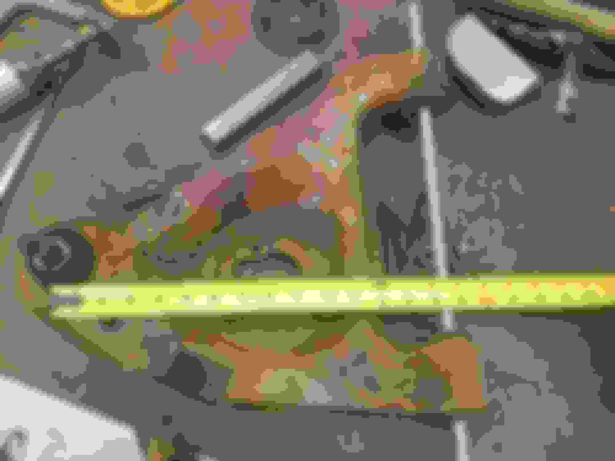
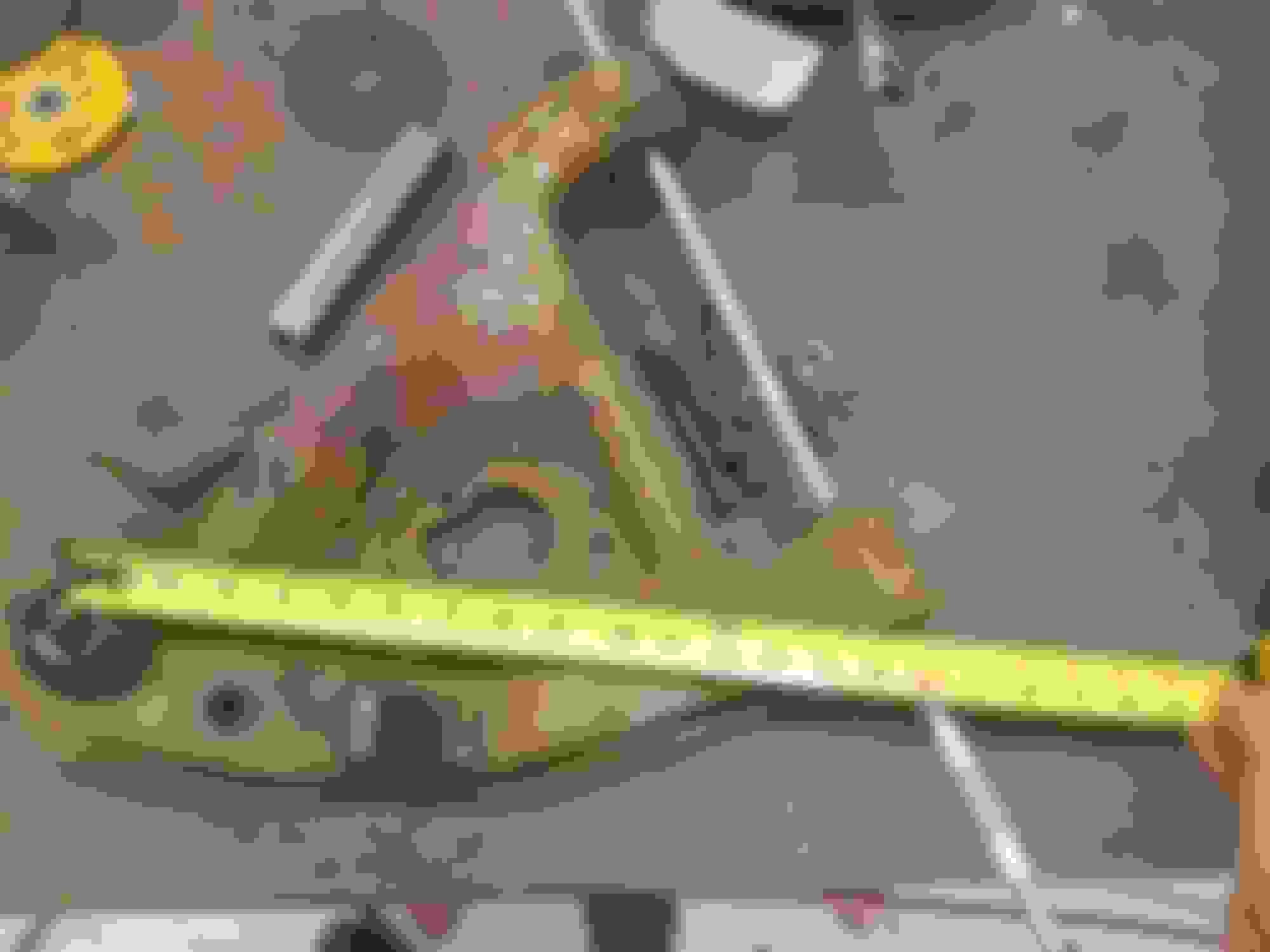
Ok the only two discrepancies I found were the length of the lower arm and the horizontal distance between the top strut mount and lower ball joint, which of course would be off if the lower arm length was different. I am using 14.5" for a lower arm, and he is using 16". If I use 16", the horizontal distance between the LBJ and top strut mount increases and I get about 4 degrees negative camber with a SIA of 18*. This all SEEMS better but I can't understand how he came to the 16" lower arm length. I am measuring from a rod going through the inner pivot points to the center of the ball joint. This is perpendicular to the lower control arm axis in line with the ball joint center. (See picture)
** CORRECTION I was measuring KPA/SAI from the upper strut mount parallel to the shaft. The correct measurement should be the upper strut mount to the ball joint, which puts me at about 14.5* with a 14.5" arm and 16* with a 16" arm (strange coincidence...)
the only way I could come to 16" would be to measure directly from the front pivot point to the ball joint center, but mechanically speaking I don't see how that is the correct measurement. Am I wrong? (Excuse the crude measuring method, but it's the best way I could think of to clearly illustrate in a picture with one hand)
Last edited by TankSinatra; Jul 30, 2018 at 01:58 AM.
Standard on-chassis SAI is +/- 14.5*. I think the spindle SAI off-car is 16.5*. Normal scrub is +/- 2.5. Again, I'm talking normal/average.
There is not much of a camber curve with struts, but you should be able to get much more static than originally posted/measured.
Many have looked at the steering arm/tie rod attachment point - no good consensus. I think it is much more promising to look at the inner tie rod attachment points on the center link. Maybe you could design a custom center link utilizing bearings and monoballs on the ends and also utilize slots and off-set slugs where the inner tie rod attaches.
Also, the spindle/strut attachment shows promise - caster/camber bolts, or DSE's JRi strut has inserts for the same effect.
I recently lengthened my adj a-arm on the back ear or pivot point by 11/16" or so, can't remember exactly off-hand. This moved the BJ forward some. Again, who knows what Stan did to his car - cars and measurements vary.
You could raise the rear LCA pivot point, and lower the front LCA pivot point on the k-member to increase anti-dive AND keep them equal on both sides.
I appreciate the input! I am a firm believer that the best designs always come from the people that are very familiar or use something all the time, so I am at a bit of a disadvantage as far as what is needed for this platform. At this point I can only design based off of theoretical numbers of what *should* be right for car in this configuration. Anything in addition to those nominal values based on input from people such as yourself are greatly valued on my part! Unfortunately the car didn't even have an engine when I bought it so even factory measurements for how the car sits under it's own weight are by the seat of my pants and any info I can gather online. Oh well this cirtainly isnt my dumbest project ever! Best case I have a particularly well handling 3rd gen, worst case I have some valuable data to build from. Either way it should be a fun project!
I've decided that instead of sticking with the oem spindle design, I'm going to convert to a more modern bolt-on wheel hub/bearing package, which should also open the door to much better brake options. I'm thinking either a 5th gen camaro or C5/6 vette unit would work. I need to pick one and model it so I can start on the new spindle design. I'm going to try and reduce SAI as much as possible and bias towards caster in order to favor a little more camber gain -- if I can get the wheels to clear the struts/coilovers, I've got a list of target numbers, but until I have all the pieces modeled up and put together in solidworks they're just targets.
If I could get in the ballpark of say 6* SAI, maybe 8* caster, and 2* camber I think I'll be pretty well set. But that will all depend on how the scrub, roll center, and of course the actually physical reality. We shall see I guess!
I do like those adjustable struts vs just using an eccentric bolt. Seems a lot stronger and won't slip. You could even make your own spacers for whatever angle you want! I may flip that around and put the oval piece in my spindle so im not limited on strut options.
as for the steering linkage itself that's a whole other can of worms I haven't quite gotten to yet. I'm definitely leaning towards a rack and pinion conversion. The cheapest option would be to use the yukon rack I have in my shop right now. It's a little wide but that's workable. I also need to check it's throw but that can also be accounted for on the spindles. OR I could go with a more modern electricly assisted unit off of a new camaro. It is probably closer to the right packaging but I am weary of the feel of the electric units I've heard mixed reviews. It would simplify the engine bay though, no PS pump or hoses is appealing... I guess I'll just have to burn that bridge when I get to it!
for now I'll just have to focus on the suspension geometry and hopefully get at least a K member cranked out soon so I can get the engine in!
Last edited by TankSinatra; Jul 30, 2018 at 03:35 AM.
I recently lengthened my adj a-arm on the back ear or pivot point by 11/16" or so, can't remember exactly off-hand. This moved the BJ forward some. Again, who knows what Stan did to his car - cars and measurements vary.
You could raise the rear LCA pivot point, and lower the front LCA pivot point on the k-member to increase anti-dive AND keep them equal on both sides.
good to know. I'm thinking he must have extended his A Arms in order to get a 16" pivot, either that or he just measured from the front pivot to the ball joint which I still think is an incorrect way to measure it. I don't see any other way to get to 16" on stock arms, but it still doesn't explain why I can't get more camber in my model. I tried another 3D printed part on my spindle and it squared right up to the axle from the strut mount holes so the angle I have there must be right. I'll need to make one more part to see if I have the distance from the vehicle centerline right...
that's a good idea with the A arm mounts as well, I've been paying so much attention to the spindles I haven't put much thought into modifying the geometry of the k member. I'm not in front of the computer now but I believe there was only about 1/2" difference in height front to back. I think squaring it up will also benifit the movement of the whole assembly as the strut's cycle will have less non linear force on it. Making adjustments like that now are easy vs once it's all fabricated!
I'm no expert. There are plenty of guys on this forum who are.
I've been around a while and picked up a few things along the way so I can at least participate in the discussions.
You'll have to use the search feature - others have used the bolt on hub design before.
I finally got the C6 hub in today and got it all modeled up! After that I played with the geometry a little and I think this should all work out pretty well!
Here is a screencap showing my current setup:
The horizontal line on the far right shows the ground plane according to the data you shared from Stan's camaro. However when I raise the wheel to that height, the shock is completely bottomed out! I'm assuming that a coilover conversion typically uses a shorter shock so it can be lowered and not bottomed out?
Anyway, the specs as it sits at this height are:
Top strut mount width: 41" (about middle of stock adjustment)
Lower arm length: 15" (+0.5" over stock)
Height from ground to bottom of crossmember: 5.6" (Custom crossmember)
Height from ground to inner LCA pivot: 8"
KPI/SAI: 13.6*
Scrub: +2.39"
Static camber: 2.76*
Roll center height: + 2.35"
Wheel/ tire specs:
Tire: 255/55 R17
Offset: -1" This is from the tire centerline to the face of the hub so depending on the thickness of the rotor mount face it could be more like 0.25"-0.5"
I'll poke at it some more but so far I think things are looking pretty good. Everything seems to be moving in positive directions and I still have a little wiggle room. I can further decrease SAI and scrub if I move the lower strut mount bolts closer to the centerline of the car so I'll look into if that will cause any negative effects with the geometry.
I also haven't looked at caster at all so it should be pretty close to stock as is, I've just been tweaking the parts on the front plane so far...
Stan's car is lowered from stock. When most of us do this, we use an aftermarket strut mount which is taller than stock - bottom of pic. This gives back some height lost, and also has much improved bearings to control the strut.
Front coilovers aren't used in a performance situation and they limit space for wider wheels; and, concentrate the weight bearing on the fender/strut mount area which is not ideal.
I was planning on putting a bearing up top, but hadn't thought about raising it so much so that's some more useful information. I dont know how they got away without using one from the factory, it has even more angle change throughout its stroke than my setup!
also going to reinforce the strut towers, possibly tying into the k member itself if I can figure out a low profile way to gusset it. Going all the way up there without some decent gussets would help take some upward force but wouldn't do much for lateral rigidity... of course it wouldn't get worse either. Tying both towers together at the top will also improve things but why not make it as stiff as possible? Option 2 would be to weld on some gusseting to the wheel well/body OR just cutting a bunch out to make room for better re-enforcement to be added...
The nice thing about starting from scratch with everything is I can do stuff like move in the lower strut mount a little so I CAN clear the coilovers even with 2.5 degrees of camber and less SAI than stock I can further increase clearance with some more backpacking if I want to sacrifice some scrub. In addition to lowering the ball joint I also raised the inner mount points on the control arm which raises the roll center significantly for only a small change.
when I get some more time to work on the project I'll take a closer look at the strut towers. Need to order some C6 brakes as well. Even with cheap OEM brakes it will be an upgrade from the OEM 3rd gen brakes! I'm actually getting pretty excited about this project!
Small update. I've spent most of the time I've had available for this project modeling the 5th gen camaro power steering rack. Very complicated piece to accurately measure and model and I was getting way too bogged down in detail that wouldn't be important to this project so about 70% of the way through I decided to just finish out the model with rough form... So FINALLY I have the rack model in the main assembly and placed roughly where it should be.
The GOOD news is, the front/ back placement is within an inch of where the factory center link would be. The mount points for the rack also fall fairly close to the K member itself so integrating them into it should be trivial. The not so good is how wide it is, and how low it needs to sit to clear the engine. If I move it forward about 1.5" from the factory center link location I can also raise it about 1.25" so I think I'll do that. See the last two pictures. It is my understanding that given the same steering arm geometry on the spindles, that moving the rack forward reduced effective ackerman on a front steer system, but since I am making my own spindles I should be able to account for most of that. It still puts the rack pretty low, so the tie rods would need to be pointed up if I mount them in plane with the center of the rack. Since I plan on using rod ends for the tie rods, I'll need to make adapters for the ends of the rack which means it will be easy to raise the mount points for the tie rods, and maybe even move them inward form the ends of the wide rack.
That just leaves the one issue of how wide the rack is. I will need to do some research on what effects this will have, but the current plan is to simply shorten the control arms and widen their mount points. An added side effect of this will be the increased angle of the control arms which will raise the roll center. Other side effects would be lower motion ratio for the shocks and springs, that would sacrifice some suspension travel but also mean lighter lb/in springs and less shock travel which I don't really see as a bad thing on a road car. I wouldn't like it on an offroad race truck but I'm not exactly planning on taking this thing to the baja 1000...
I really can't wait to get off my *** infront of the computer and solidworks and get to actually fabricating it, but good design now will hopefully prevent headaches and redos down the road.
Spent a good 2 hours on adjusting this thing. Moved the inner LCA pivots up and out. Moved the upper strut mounts up 2" Shortened the LCA's to match the new inner mount points. At the height I have it set at currently the specs are mostly the same but the roll center has raised significantly, much closer to the estimated CG of the car!
Ride height to bottom of cross bar: 5.25"
Static camber: 2.55*
SIA: 12.44*
Roll center height: 6.43"!!!
There is also very little camber change as I cycle through a few inches of wheel travel, bottomed out, there is only about a +1* change and 0* camber is about 3" down.
Going to put this down for tonight and think on it some more but I'm happy where it is headed. Just need to pick up some brakes so I can design the spindles.
This is what I have come up with. I made my own spindle it has pro ackerman the SAI is 11 with the roll center of 3.5" and it has no bump steer. Oh and the 3" hole on the unibody is a brake cooling duct.
This is what I have come up with. I made my own spindle it has pro ackerman the SAI is 11 with the roll center of 3.5" and it has no bump steer. Oh and the 3" hole on the unibody is a brake cooling duct.
Sweet! - pun intended.
Lots of quality showing - more pics?
What are your thoughts on SB size and springs?
very intresting, i did this with a ruler and graph paper years ago
Fortunately for me, CAD simplifies this process considerably! Of course good ol' paper doesn't crash and erase your work since last "save"
Originally Posted by tvc 15
This is what I have come up with. I made my own spindle it has pro ackerman the SAI is 11 with the roll center of 3.5" and it has no bump steer. Oh and the 3" hole on the unibody is a brake cooling duct.
Very nice! I'm liking the cleaned up firewall as well! What size rotors are you running? I have some 14" 5th gen rotors in the mail I'm waiting on to measure and then place the caliper and finish the spindle design.
The other night I came to the fantastic realization once I mirrored the subframe tubes that the steering shaft input for the rack was residing inside of it! Grrr... Had to shake up a lot of what I had done already but I think I've just about got it now. I've refined engine placement as well, I actually bolted it to the transmission and lowered the car over it yesterday. Pretty much what I expected so that's a relief. Just need to trim the tunnel to fit the beefy 6l80e in there!
Additional tweaks I'm thinking about are lowering the rear LCA mount for a little anti dive, and squaring up both mount points more parallel to the forward axis of the car. I'm a little unused to having them at such an extreme angle, I'm used to trucks where they mount to the frame rails basically parallel (angled like TOE, but for the LCA). I'm honestly unsure why it was done like this in the first place? Maybe it was just packaging? I think my best bet will be to make them perpendicular to the strut travel/ caster angle. This will help with steering rack clearances and add back in a little anti dive.
This is what I have come up with. I made my own spindle it has pro ackerman the SAI is 11 with the roll center of 3.5" and it has no bump steer. Oh and the 3" hole on the unibody is a brake cooling duct.
This is what I have come up with. I made my own spindle it has pro ackerman the SAI is 11 with the roll center of 3.5" and it has no bump steer. Oh and the 3" hole on the unibody is a brake cooling duct.
I am pretty sure you could make some money on those spindles, this is what some us where hoping the aftermarket would do, fix the anti Ackerman and other spindle issues. Keep up the good work and keep us posted as the project continues and the results after its done.
I am pretty sure you could make some money on those spindles, this is what some us where hoping the aftermarket would do, fix the anti Ackerman and other spindle issues. Keep up the good work and keep us posted as the project continues and the results after its done.
mine will be set up for the EPS rack so the steering pickups might be a little different from the factory steering box but I could just as easily design and build ones for a different configuration if people want to buy them. Hell I'll sell the whole front end if people want it! I ended up going a different direction from Corvette brakes, so I actually need to order some slightly different hubs now, BUT what I'm working with will be an amazing improvement over stock, and only about $350 per side for OEM components and 14" rotors! I'll post more details later but I'm pretty excited about these things!
The rotors are 14" the firewall was pushed back and I'm starting with 900# springs with a 1 1/4"x 1/8" wall swaybar. Also the spindles on my car would never work on a more stock based car and it would also have to have a rack because of the short steering arms.
Nice. Now I'm thinking about moving my firewall back too, especially because that would help with the placement of the massive EPS rack I'm using... but then again I REALLY need to stop adding complexity to this project. I think I can make it work with what I have now, I'm putting the engine about 3" from the bell housing mount plane to the passenger side firewall. If all else fails I'll bust out the saw and start hacking!
I know there's lots of guys that want bolt on parts, but at a certain point you have to wonder when it's better to just slap a bandaid over the factory garbage OR start from scratch with purpose built parts that might not be compatible with other stock parts. What I'm working on just wouldn't be possible if I was sticking to the box of factory geometry which is exactly why the project has advanced from a quick and dirty subframe and control arm fabrication to a basically complete redesign.
How did you get started using CAD and how long have you been doing it? I wish it was a skill I had, I can see it would be very useful.
I'm actually self taught. I started messing with it when I was about 13 or 14, my dad used it for mechanical design for aeronautical and avionics stuff, robots, medical devices, lots of interesting stuff. Motorsports are more my passion so almost 15 years later I'm using what I've slowly learned and applying it to that industry. I'm hoping to get some more steady work with my own shop designing and fabricating stuff for cars and trucks so I can do it full time!
I use solidworks almost exclusively because that's what I've always used. If you're looking to get started in CAD I would suggest checking out Autodesk fusion 360, they have a licence that is free for non commercial use. Other than that YouTube is your best friend there are lots of tutorials out there!
I actually started with solidworks, but I use autocad for work now. I felt that solidworks was SO much more user friendly, and better for the type of design work you're doing. It's great 3D modeling software. The autodesk mobile apps are free and can do some pretty cool stuff, but obviously they are fairly limited.
The rotors are 14" the firewall was pushed back and I'm starting with 900# springs with a 1 1/4"x 1/8" wall swaybar. Also the spindles on my car would never work on a more stock based car and it would also have to have a rack because of the short steering arms.
It is possible to have short steering arms with stock steering I have them on mine works really well, I AX my car so the faster ratio with the short arms works well and gives better ackerman than stock. I would be interested in the better spindle geometry and lighter weight that you guys designs look to provide. Mine works really well as is but I am always looking for areas to improve, thanks for putting your knowledge and effort into these.
Remember that arm length and Ackerman geometry are mostly independant of eachother. The arm length is just motion ratio/leverage longer arms make steering lighter but will steer less for the same center link travel.
Basic Ackerman geometry comes from the placement of the outer tie rod joint relative to the steering axis. Imagine a line from the center of the rear axle through the steering axis, if the outer tie rod joint is on that line, you have classic Ackerman geometry. Of course there are more contributing factors because as the various linkages move through their range of motion everything else is moving as well, but that is less prominent on a rack vs steering box. It is possible to change the steering arm length with little effect on the Ackerman geometry as long as it stays on that line.
the problem comes on front steering cars because the outer tie rod joint needs to be so far outboard, especially with a longer steering arm. Eventually you end up with interference with the wheels. I have a feeling GM decided to favor light steering over better Ackerman geometry given the confines of the factory wheels. If you use a shortened steering arm and or larger wheels you can push the mount point out farther to get back on that Ackerman line.
Of course there are also schools of thought that promote anti-ackerman geometry for better handling, but I think that requires more study and tuning than I'm willing to do for this project haha!
Just visually your car appears to be neither pro nor anti ackerman. Zero ackerman is definitely better than anti. I have had the setup you are running and you are correct it works fine, but the problem is any looseness in the steering box will be noticed immediately.
Remember that arm length and Ackerman geometry are mostly independant of eachother. The arm length is just motion ratio/leverage longer arms make steering lighter but will steer less for the same center link travel.
Basic Ackerman geometry comes from the placement of the outer tie rod joint relative to the steering axis. Imagine a line from the center of the rear axle through the steering axis, if the outer tie rod joint is on that line, you have classic Ackerman geometry. Of course there are more contributing factors because as the various linkages move through their range of motion everything else is moving as well, but that is less prominent on a rack vs steering box. It is possible to change the steering arm length with little effect on the Ackerman geometry as long as it stays on that line.
the problem comes on front steering cars because the outer tie rod joint needs to be so far outboard, especially with a longer steering arm. Eventually you end up with interference with the wheels. I have a feeling GM decided to favor light steering over better Ackerman geometry given the confines of the factory wheels. If you use a shortened steering arm and or larger wheels you can push the mount point out farther to get back on that Ackerman line.
Of course there are also schools of thought that promote anti-ackerman geometry for better handling, but I think that requires more study and tuning than I'm willing to do for this project haha!
Because of the angle of the stock steering arm when you shorten it it gradually loses anti ackerman. Also I don't believe anti ackerman has any place in a (handling) car, might be useful for Bonneville and going straight, but that's only my opinion.
I shortened the steering about 2" a few years back. It allows the tie rod end, or rod end in this case , to tuck inside the wheel and provide many options for akerman settings. I ran 295/35/18 tires on 10.5" wheels and could turn to full lock at parking lot speeds with no squeezing, hopping, noises nothing. It is well worth exploring.
The rotors are 14" the firewall was pushed back and I'm starting with 900# springs with a 1 1/4"x 1/8" wall swaybar. Also the spindles on my car would never work on a more stock based car and it would also have to have a rack because of the short steering arms.
you sir might give me a run for my money, looking good
Been super busy with a contract at work that should hopefully end up paying for the rest of this car so it has been getting my focus. Definitely haven't forgotten about this project though, I even still habehthe chassis sitting on the lift! I did however get an 85 for cheap that I use as my daily so there is less rush on this one, which means I'm very tempted to go a little more extreme on the build. A little more racecar biased I think! My work deadline is the end of March so after that I should be back with some decent updates!
It is possible to have short steering arms with stock steering I have them on mine works really well, I AX my car so the faster ratio with the short arms works well and gives better ackerman than stock. I would be interested in the better spindle geometry and lighter weight that you guys designs look to provide. Mine works really well as is but I am always looking for areas to improve, thanks for putting your knowledge and effort into these.
I really like what you did here. When you say you shortened the arm 2", do you mean along the arm or do you mean radially from the ball joint pivot?
Also, how do those Viking struts perform for autox? are they the Warrior or Crusader valving?
If I'm measuring properly, shortening the steering arm radius from the ball joint by 2" reduces the required steering travel to ~5 1/2". Can anyone confirm this?
If I'm measuring properly, shortening the steering arm radius from the ball joint by 2" reduces the required steering travel to ~5 1/2". Can anyone confirm this?
I have no doubt. With a shorter steering arm and stock steering gear you reach the stop before full travel.
I'm interested in the actual necessary travel to reach the steering stop with a 2" shorter steering arm. The very few people who have actually shortened their steering arm (including you) could measure this as could anyone with a shortened Racecraft spindle. I attempted the take the measurements with my spindle on my bench top, so what I got is very much an approximation.
I'm curious if anyone has tried to measure this on the car.
Update on the project: I got a bit of a hair brained idea and hacked the front of the car off forward of the firewall. Seemed like a good idea at the time, I'm taking more of a clean slate approach to the engine swap and suspension. Full tube front end so lots of room for activities. I'm currently working on the primary tubes and blocking out where everything is going to go. Once I get the main tubes that connect to the body laid out I will model it up and get to work on the engine mounts and suspension.
The down side to this is I won't have "bolt on" parts that mount to the existing unibody frame rails...
The up side is I'm even less constrained by what was there before. The plan is to widen the stance and probably go with a double wishbone design. I'm still planning on using the new gen electric steering rack but mounting it will be a lot easier. And I'm going for as.much steering angle as possible just to push the limits!
I'm thinking I might start another thread once I progress a little farther.