When you click on links to various merchants on this site and make a purchase, this can result in this site earning a commission. Affiliate programs and affiliations include, but are not limited to, the eBay Partner Network.
Engine SwapEverything about swapping an engine into your Third Gen.....be it V6, V8, LTX/LSX, crate engine, etc. Pictures, questions, answers, and work logs.
the first thing you need to do with the new RAM push conversion clutch is make sure you have good measurements to understand the shimming that is going to be required to have the hydraulic throw out bearing in position with the right gap.
RAM sent good instructions with the need to take 3 critical measurements to find this gap. Basically the crank flange to the engine block, the flywheel crank flange to pressure plate finger distance, and then the throw out bearing to bell housing end.
after i started to work to get these measurements, i didn't really like the repeatability as i needed to set the flywheel on something to simulate the back of the crank flange (used a big hole saw), etc... i am sure it would work, but it seemed like i could get to the right gap with a more accurate and easier method after i thought about it
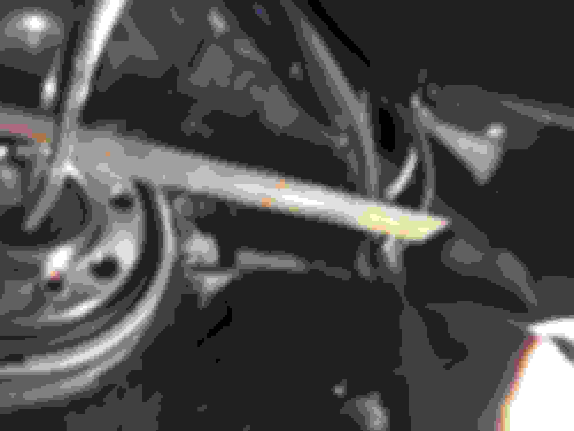
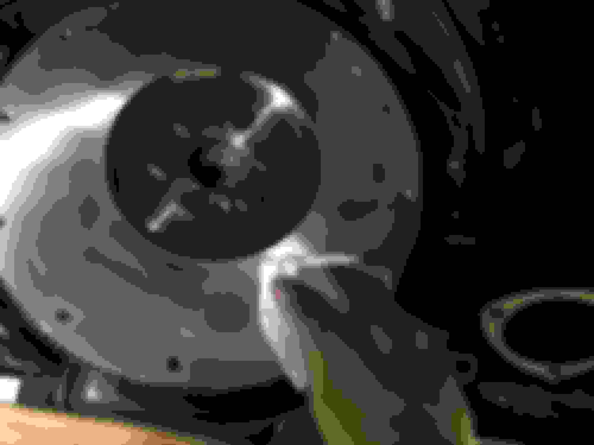
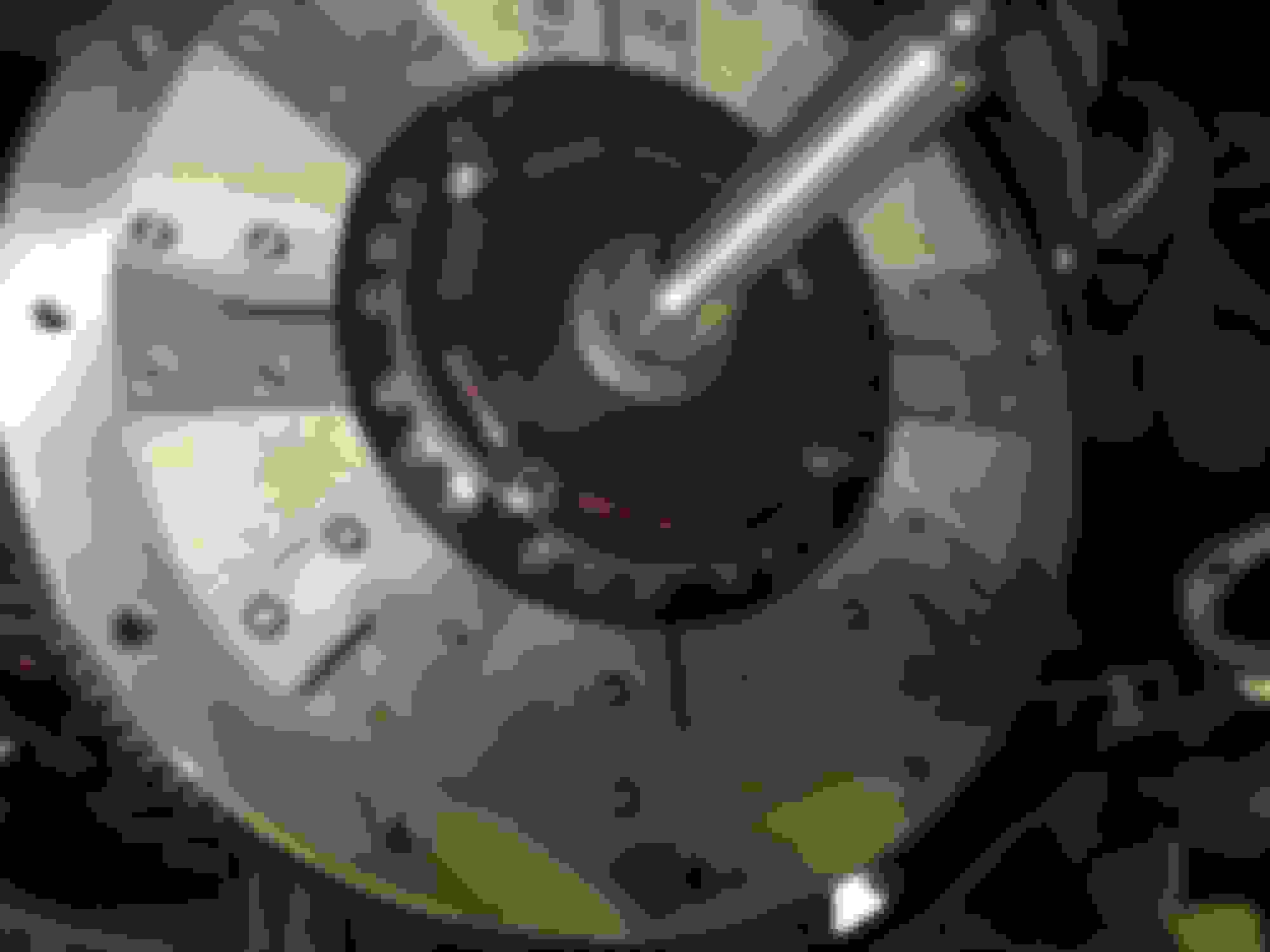
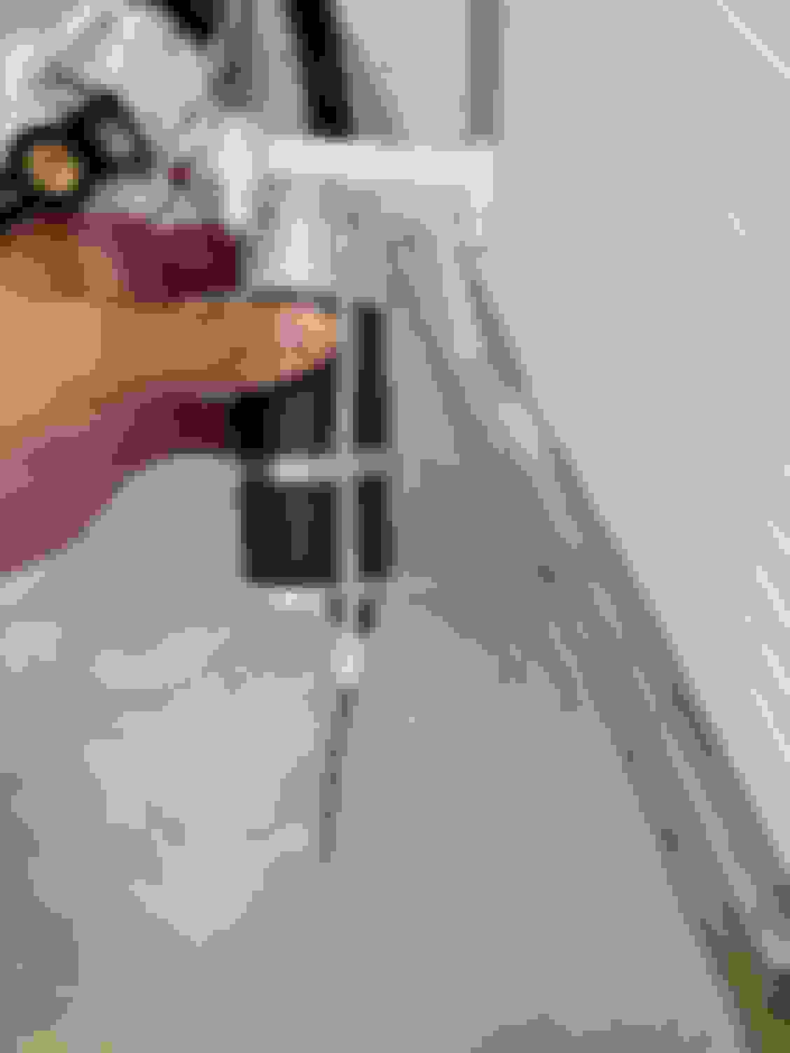
what i decided to do was eliminate some of the measurement error by getting rid of some of the intermediate measurements needed. i decided that i would mount the flywheel, disc and pressure plate fully installed, mount the bellhousing to the engine block fully installed and then measure the gap between the end of the bellhousing and the pressure plate fingers. i would then install the hydraulic throw-out bearing on the transmission and measure its face distance to the end of the transmission frame. with these two measurements i would know the gap and i would be more confident in the numbers and measurements. in addition this is how i install the transmission anyways so accuracy was improved in that it was measured in the actual as installed position
the hydraulic throw out bearing floats and you utilize shims to have it properly spaced for an initial gap of 0.150 to 0.200"
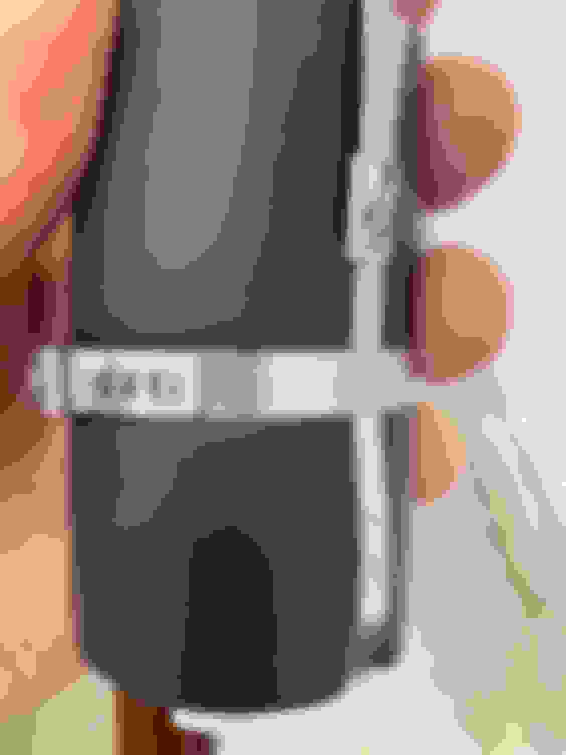
i found with no shims i would have a bearing to pressure plate gap of 0.355".
i first then looked at using 3 of the supplied shims and got down to a measurement of 0.198 - 0.206 vs my 0.205 prediction.
in the end i added the 4th shim (used all 4 included shims in the kit) and ended up with an as measured gap of 0.180 to 0.183" so basically right on target. (the variation in measurement was measuring the throw-out face distance on either side of the transmission. note when you measure you need to push in on the bearing to make sure everything is flat
also on the shims clean them up before applying, they still had the laser cut out burrs on them that made them not seat flat initially
Also I had automatically re-assembled my starter with the same shim pack i had used originally and didn't think about needing to re-measure for the shim (this was the Saturday before Palm Sunday). On Palm Sunday our church and several others had a car procession in a state park since we can't meet in person for church as something fun to do. It was a nice day so I took my 91 Formula and as I went to restart it as we were getting lined up and ready to go from the park lot the starter would engage and make that terrible grinding sound (which it has never done before or since). I moved formula slightly with my foot to rotate the engine and it restarted right away and has been fine since (maybe i have one bad tooth, but never had any trouble before). Anyways it got me re-thinking about my starter on the 88 Camaro and a good thing it did as the shim pack needed to be changed. I think God was again looking out for me as he has done so many times in my life!
So long story short, the RAM flywheel was slightly different in size than the one i took off, to the point though that the Bendix would not be able to even engage the teeth with my original shim pack. In the end i added shims (from 5/64 original to 8/64 with RAM flywheel) to get a clearance of 0.023 tooth and also the 5/32 allen key method. Glad that worked out before i put everything together!
with that complete, now the need to connect the hydraulics, bleed the system, and measure the actual throw out relative to the pedal. too much throw out can damage the bearing. fortunately i am already using a Hawks adjustable master and therefore was able to dial the throw out to the right target by adjusting the pedal to master rod. the target is between 0.400 and 0.500
in the end i adjusted my pedal so that i achieved a throw out of 0.442"... this number combined with my gap of ~0.180 insured that i was below the 0.800 max travel allowed by the bearing
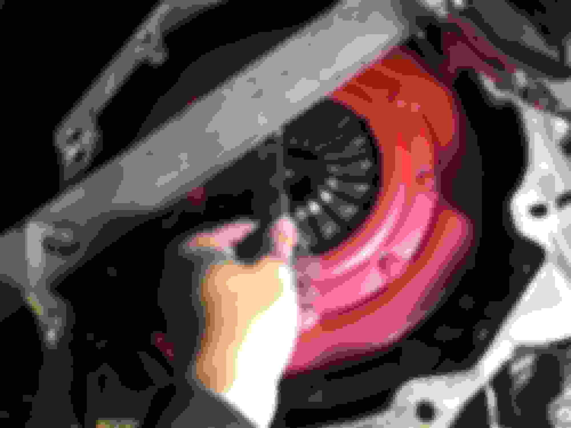
after that was complete, then it is just about securing the lines inside the transmission and making sure the rod that the bearing floats on is cut to the right length. i made sure to position the fittings on the bearing so that they ended up tilting towards the rear of the transmission to make sure the would not be too close to the pressure plate when they moved. i also used a loose fitting clamp to the lines to make sure again they stayed out of the way of the rotating pressure plate
then it was just a matter of bolting the transmission back into place and putting up the rest of the underside (torque arm, exhaust, etc)… using the RAM steel alignment pin in the clutch install has always made sliding these transmission in very easy. it is much more precise than the plastic ones
the clutch pedal to me feels much better. as it snowed here on Friday i have only been able to drive in my driveway basically in 1st and reverse yesterday but it felt great, engaged well, etc... will need a full road test and time to tell, but so far it seems like a big improvement
a couple of updates, i have been working on this Camaro constantly throughout the summer as i have had a lot of trouble with WOT fuel fuel pressure and intermittent misfires
the good - the RAM clutch conversion works great. it is fantastic compared to the original LT1 pull clutch. I like it so much i will be converting another one of my Camaros that has a LT1 pull type clutch when i get a chance
the bad - earlier this summer i began to have problems with low fuel pressure at WOT when the tank would get somewhere between 1/2 to 1/4 full. turns out the venturi line had broken at the bucket connection (split open) and the combination of not having that and also not having the FPR in the tank which directs fuel back into the bucket (i just pulled it out as noted earlier due to having a FPR on the fuel rail with the RAMJET) caused the bucket to become drained and unable to keep up at lower fuel levels. The venturi is a nice idea but over time it seems this line is prone to crack, you are beholden to either stock or Racetronix pump, and new buckets don't seem to be available with the venturi anymore so i wanted to do something better which i will detail in additional posts below
the bad2 - i kept getting intermittent misfires that were very hard to datalog as they would occur 100 miles apart. i had ended up basically trying almost everything on the ignition system one by one (ICM, coil, plugs, wires, cap/rotor, distributor, added CDI, etc, etc) when i finally captured a log on the holley that showed the holley seemed to be very occasionally miscalculated the crank signal feedback from the ICM. As soon as I installed the CDI box it happened as i was backing out of the garage and continued constantly. Basically it seems like the Holley HP can be very prone to electrical noise. I ran new shielded wire from another one of their harnesses, moved the plug wires, etc but couldn't get it to completely go away. Bottom line is i lost confidence in the Holley and pulled it out around July 4th weekend and installed an EBL P4 with the same ignition set up. Problem immediately solved and within 3 days had the RAMJET running better than a year and a half of missing with the Holley. The Holley has some nice features but it is very primitive in many areas as far as available tuning tables (like idle) and with the EMI issue i just said chuck it!
so when i realized i was getting low fuel pressure issues (good to have a fuel pressure sensor) and pulled out the pump from the 4th gen tank i saw that the venturi line was split, etc as detailed above. To get this issue temporarily behind me i bought a Delphi FG0154 and just dropped it in. This is capable of currently supporting my RAMJET 350 and got me back up and running. But as I have other projects with bigger fuel needs I needed to get established what I am going to do for fuel pump as i have the following objectives
- 4th gen tank, it doesn't rust, is easy to put in and take out of the car with the removable neck, vents well, fits right, has good mounting for the pump, etc, etc, etc
- need a fuel pump / bucket solution that supports 600HP and will run with the tank nearly empty
- need a sender solution that is direct interface to stock gauge
over the past month i have been working on a solution and think i now have it
i will detail in additional posts what i did
Last edited by alan91z28; Dec 20, 2020 at 03:39 PM.
the default standard for utilizing the 4th gen tank has been to utilize the original fuel bucket and an upgraded 255 l / hr Racetronix pump that incorporates the venturi. i have used this method in the past (on my LS3 swap for example) and it has worked great. the problem though is that original fuel buckets are now getting quite old and brittle and new replacement pumps seem to now be all upgraded designs. Even the E3368M now appears to be upgraded in such a way that the venturi is no longer utilized. They have a much different internal bucket arrangement.
In the end i decided therefore to think about what i could do to allow a brand new pump bucket to be utilized so its integrity was sound for another 10+ years, a pump system that supported 600 hp, be able to run near empty without issue, and the ability to have a 0 - 90 ohm sender right to the factory gauge.
In the end this is the list of parts that i utilized
- New Herko 4th Gen '99-'02 LS1 Pump and Bucket Assembly, Herko 084GE
- Fuel Pump Walbro Style, I used GSS342 as i wanted 255 l / hr, needed the right inlet / outlet orientation, and inlet filter connection for a push on 11mm inlet and locking pin... you should be able to also utilize higher flow pumps with this method
- Flexible convoluted fuel tube Racetronix FFT-180B (180mm x 8mm) ... this is a little long and i have order 160mm length for future but not confirmed
- Fuel Pump Foam Hose Sock from Racetronix
- Oetiker pinch clamps to connect fuel tube to pump and top of bucket assembly. 11.9mm for pump, 13.3mm for top connection
- Crack resistant teflon pfa clear tubing for return connection, McMaster 5733K78 cut to 220mm length
- Stainless band clamp from summit SUM350131 14" length and Oetiker pinch clamp 45.5mm (16704685) to secure new pump to Herko pump assembly
- Holley Hydramat 16-111 3" x 15" with 11mm and lock pin fittings
- GM 25319676 or Herko FC31 0-90 ohm fuel level sender
Last edited by alan91z28; Aug 9, 2020 at 06:53 PM.
First thing is to disassemble the new Herko pump assembly as we are going to toss the pump, toss the sender, toss the FPR, and modify the bucket
- Remove sender from bucket assembly
- Carefully cut convoluted fuel pump outlet hose at top of pump assembly to allow tube to be disconnected from top assembly
- Separate bucket assembly carefully by pressing on two side tabs and then it will slide out
- Disconnect pump wiring connector and you can then toss the pump
- Disconnect the wiring connector on the top of the pump by removing first the red secondary lock and then squeezing in on the black tab the entire black connector can come out
- Remove the sender pins from this black connector and you can toss the 4th gen sender (you can use a small safety pin to disengage the senders pins that are in the black connector if you do not have the official tool)
- Carefully remove the FPR (if running an external FPR which i am)... to get this out of the herko style pump assembly you need to do a little twisting of the mounting fixture due to the position of the bucket rods, do it gently and you can get the FPR out
- On the bottom of the bucket remove the strainer, this can also be tossed
The bucket and top assembly needs to be modified so it will accept the new walbro type pump, so that you have access to allow the new pump to connect to the Holley Hydramat, and i also added a small hole on the bottom flat side to insure the pump bucket fills initially as i wasn't sure if the pumps float valve on the bottom would be completely covered by the hydramat, and how well the large hole would allow it to fill as the hydramat is completely covering it once installed. now that i did this first one i do not believe this small side hole is needed at all
- Drill 2 3/16 Holes in top assembly shelf to allow new pump retention with stainless steel tie wrap
- Open up existing back hole in top assembly shelf to allow fuel return line tube to pass through without binding
- With 1 3/8 Hole Saw Drill out bottom of bucket using existing bottom bucket radius as a guide (largely will be centered on original bottom bucket feed point
Now if eliminate the FPR the top of the pump assembly is modified to take off the FPR black mounting receptacle and make sure full returns to the bucket direct (note i think this step can be done easier in the future with a FPR fuel bypass plug that i found from ICT but i didn't have it during this time... also you could argue with this mod you don't even need to worry about the fuel directly returning through the bucket so just pull the FPR and be done. I wanted the fuel to go into the bucket
With an air body saw with fine blade and a dremel the fitting can be removed. this will expose the fuel return nipple that a tube can be attached to flowing the fuel to the bucket. note that this black assembly is not on with any adhesive, etc so if you take your time it will come off not too bad, just need some patience as it is in a tight spot with a connection on the top and one molded around the post
After cleaning everything up and making sure all the debris is gone, we can re-assemble the fuel pump assembly with our new system
- Connect one end of the 180mm x 8mm convoluted fuel tube to the new fuel pump. Secure with Oetiker 11.9 pinch clamp and rotate pinch to center of pump
- Install foam sleeve on pump
- Install Oetiker 45.5 pinch clamp around pump but do not pinch at this point
- Insert the new pump into the shelf assembly, note that the fuel pump inlet and outlet should be towards the center of the pump and the electrical connection to the side
- Pass 14" stainless steel tie band through the two 3/16 holes that were made on the pump assembly shelf and feed them through the Oetiker 45.5 around the bottom of the pump on the far side of the securement post vs the 11mm feed opening back through the Oetiker 45.5 and tighten
- Once 14" stainless steel band is installed and tighten gently pinch the Oetiker 45.5 (i just used this as a stabilizer clamp to keep the tie wrap in place and you could probably get away without it
Now you can secure the feed and return tubes to the top of the pump assembly
The return tube is easy, take the McMaster 5733K78 (8mm ID) cut to 220mm length and slide onto the upper fuel assembly body fuel return nipple. Pass the tube through the 1/2" hole that was opened up on the mid shelf
The fuel feed tube is harder. First slide the 13.3 Oetiker Clamp onto the tube. The 8mm tube diameter is smaller than the 3 prong feed nipple on the top of the pump. Carefully use a heat gun to heat the end to make it pliable. Over heating will ruin the tube (you will get blistering on the outside of the tube if it gets too hot). Also if you have a smooth tool to help form the inside larger before attaching it can help.
Once installed position the 13.3 clamp and pinch
At this point you can also attach the wiring. Take the new 0 to 90 ohm sender and place its pins in the appropriate spot in the black connector. Attach the pump connection and the black connector to the top of the assembly. Re-insert the secondary lock. Note that it could be advantageous especially on larger pumps to replace the internal pump feed wiring to a larger gauge
Now we can put the pump assembly back together, install the Hydramat, and snap the fuel sender in place
- The top and bottom assembly will slide right back together. You may need to slightly bend the return tube while getting the assembly first to slide in together
- As you can see from the bottom of the bucket you have a nice new pump waiting for a good strainer / feed system. The Holley Hydramat is a good (and expensive) choice as it is large and really wicks up the fuel. It has been well proven in autocross and other track events. It will be held down on the bottom of the tank by the pump assembly itself. Note that i clipped two of the extra retainment ring positions off for clearance of the bucket hole. Also i positioned the hydramat so that it ran side to side with the long side towards the fuel tank inlet (drivers side). This keeps it out of the way of the fuel sender
- The fuel sender will slide into the buckets existing side rails. The secondary lock does not engage with this style of bucket so i drilled a small hole with 1/8" drill to run a tie wrap through. I didn't want to take the chance on damaging the sender board by trying to swap it to the original sender piece with the Herko pump but that is likely another option
Inserting into the fuel tank itself is straight forward. What i did was insert the long piece of Hydramat first, then the sender float, and then bent down and in the smaller side of the Hydramat. Orient the pump and lock in place. Put tank back in and away you go... Need some good run time on it, but so far so good and i think this now allows a new bucket with all the needed features
also to me the 4th gen tank itself is so much more easy to work with. i always pump the fuel out first using the pump itself and then slide the neck off and you can drop the tank out easy without needing to take a lot apart in the rear (i take down the muffler assembly, pan hard bar, pan hard brace, heat shields, tank straps, and tank... easy in and out no trying to twist around or needing to further drop out the rear
Last edited by alan91z28; Aug 9, 2020 at 08:13 PM.
That's good news. I need to drop my tank again and change my module so I can have a working fuel gauge again. The Herko setup is cheap enough that it's worth buying to experiment with for the past ~2 years I have to go by mileage to know when I need to get gas again. At least when I get close to empty tank the needle goes to about 1/2 tank
just a little follow up... over the last several weeks i have been running this Camaro pretty hard and gone through several tanks of gas running them below 1/4 tank before refill. The pump assembly with the Walbro and Holley Hydramat is working great. Today i ran it down to where the gauge was starting to touch the red and at the gas station put in almost 14 gallons... so i was within ~2 gallons of empty or so. It was running strong WOT pulls, corners, etc with no problems right before i got to the station. I don't usually run that low anyways out of respect for pump cooling and longevity but over the past couple weeks wanted to see over a couple tanks of gas that it would perform without issue. The Hydramat in general has very good reviews and my experience so far supports this.
Also my EBL P4 has been running great as well... no unexpected random misfires, great idle, better off idle tip in and while certainly not a scientific study i have noticed that my mileage is definitely better enough to be noticeable. I should have ditched the Holley sooner, I spent a whole season trying to chase down the random misfire that at this point was almost certainly driven by Holley's higher sensitivity to EMI. Also there is just no comparison to the available tuning features in the OEM based ECMs vs Holley in my opinion. I really liked in the Holley the flexible logic algorithm ability and some other features but in the end it just didn't work out for me and I won't be going back.
Last edited by alan91z28; Aug 26, 2020 at 06:21 PM.
One thing I have been thinking about is my brake set-up on several of my swaps. I have been using LS1 front discs with PBR 1LE/C4 rear discs (12" rotor), 4th gen booster, 4th gen master, and wilwood adjustable proportioning valve.
I actually just updated my son's 87 Formula with the same set-up as shown in detail in this thread and was when I got to initially setting the prop valve I forgot where I ended up so relooked at this '88 for guidance. After a quick look I saw and then remembered I have the prop valve adjusted all the way in, ie max braking pressure / no proportioning. Sure enough setting the Formula like that resulted in no ability on test to have the rears seem to have any problem locking up and causing a problem vs what the front was doing.
So that got me thinking back to my question I actually had and never got to with this swap on what is the front-back ratio this set-up is actually giving
Two great resources I used to think about this-
1. First a book I have that is very informative - Brake Design and Safety by Rudolf Limpert
Bottom line is even with full line pressure going to PBR rears my front - back ratio is about 74 / 26... so easy to understand why I have the Adjustable Prop Valve all the way in. A more ideal ratio is in the 65 / 35 range but obviously that can not be achieved with the current set-up.
Clearly the next step in think about improved braking if I want something more is thinking more about the rear than the fronts.
Let me know what you come up with for rear brakes. I'm in the same boat but with abysmal choices because of a 12 bolt C-clip eliminator axle. If I had a different axle it would make things a lot easier. I've kept the 1LE rears so far only because of the fantastic parking brake (with manual trans). However, the other day I locked up the front brakes at over 100 mph. It became sorely obvious I can't even track my car it is so bad.
I have some rear Hawk pads (more bite) that I want to install this winter. And I'm probably going to ditch the drag radials which will help too (less rear grip). But honestly, I'm so far off from target that I just don't see how the PBR calipers are ever going to work out unless I reduce front brake capability.
Let me know what you come up with for rear brakes. I'm in the same boat but with abysmal choices because of a 12 bolt C-clip eliminator axle. If I had a different axle it would make things a lot easier. I've kept the 1LE rears so far only because of the fantastic parking brake (with manual trans). However, the other day I locked up the front brakes at over 100 mph. It became sorely obvious I can't even track my car it is so bad.
I have some rear Hawk pads (more bite) that I want to install this winter. And I'm probably going to ditch the drag radials which will help too (less rear grip). But honestly, I'm so far off from target that I just don't see how the PBR calipers are ever going to work out unless I reduce front brake capability.
I have been using on several of my 3rd gens EBC Yellow Stuff brake pads. On this camaro I have the EBC yellow stuff and on my son's Formula currently have stock type brake pads (both with 4th gen LS1 front brake, 12" PBR rears)... there is definitely quite a difference between the two especially in that initial bite and no fading, just solid braking. the only down side is the yellow stuff are quite high dust compared to the stock type ceramic... so i should add I am impressed enough about the real street use difference I am going to standardize on yellow stuff pads for any of my third gens with upgraded brakes and put up with the need to clean the wheels more often
I am very much still debating what to do. Likely now that Hawks sells new backing plates I probably will at least move to LS1 type rears for future builds. I have been looking at Wilwood but not yet sure about a much better setup that I would have with the 17" style OEM Hawks wheels
Last edited by alan91z28; Nov 19, 2020 at 06:10 AM.
Did you use the original RamJet 350 sensors ( tps, iac, map,ect...) and injectors with the Holley EFI HP?
when i was running the holley hp, yes i used all the ramjet 350 sensors, however if i remember right i might have had to change something in the wiring for the IAC, ie i believe the holley uses a chrysler default wiring... for injectors i changed to 36 lb/hr holley injectors
i ended up with a lot of struggles with the holley not working well and went to the EBL which has worked great
a couple years ago i ended up cratering the engine with a terrible internal water leak ... i have since replaced it with a blueprint 383 and now have a FIRST TPI on top... just getting ready to fire it up for the first time, will be using the EBL... i need to get some updates into this thread!
Thanks for the great information. You have saved me alot of work. I purchased a new RamJet 350 in 2002 to install in my 1938 Chevy coupe. I have put up with the MEFI3 system for 22 years and have finally decided to make my car run like a car instead of a boat.
just as an update... i ended up summer of '22 with a bad internal water leak that "milkshaked" the engine bad plus likely an overheat... since i decided to pull the engine i thought why not do an upgrade vs the RAMJET... my work schedule really slowed me down, but i ended up putting in a Blueprint 383 with a FIRST TPI intake... after creeping along on the last 10% of the project, i actually got it fired up for first time a couple weeks ago
I am using the EBL P4 and already have it tuned it reasonably well after only 3-4 drives... now have great starting, idling, and moving coast down / stop stability without stalling all after only about 50 miles of driving... i am letting the engine break in some more before i get on it, but even 50% throttle it feels pretty good
A couple quick tuning tips for a good first start-up...
- Take the time to prelube the engine, ie spark plugs out, fuel pump fuse pulled and build real oil pressure prior to attempting to start
For the initial tune
- Use Good Injector Data
- Have Distributor Reasonably Aligned and on right part of the rotation, have balancer marked were your set point with ICM /ECM disconnected will be, i am using 10 deg
- Have your adjustable Fuel Pressor Regulator set close just using the prime key on
- Have a reasonably realistic VE table
- Think about your crank fueling table, many times way to rich at cold / cool conditions
- Have a realistc idle setting and think about the interaction of your thermostat, fans, etc so you can have a steady warm point to dial in IAC / throttle set screw
- Have a plan before starting on what you / your helper is going to do once started (ie confirm fuel pressure, confirm timing, confirm IAC / throttle set screw, etc)
by doing these things i was able to get good starting, idling, driving stability in a couple of drives of ~50 miles total
a couple of things i do at first start-up and initial drives
- record everything with the What's Up Display EBL program... data is everything to get it dialed in
- get your FPR setting right asap after start-up, ie you have your injector data right so get the fuel system in total right
- as the engine warms up get that timing set point dialed in to the setting you have chosen
- i have a wideband hooked up and i watch it, but i use BLM / INT closed loop adjustment to make gross changes to VE table on the initial drives vs trying to be precise... ie i adjusted entire table leaner by 10% after first drive and then from 3000 RPM down by another 5% after second drive as i had started with a reasonably shaped VE table, now i am ready for precise learning
- with engine at steady state idle at full temp, get your throttle screw set right, ie should have IAC around ~30 steps or so is how i do it
Also a key learning from my viewpoint on the FIRST TPI install... very well made, great instructions, and awesome support from Ken...
I did though end up with a leak/weep on the passenger runner lower middle bolt that goes into the intake coolant chamber. I did per notes and instructions make sure i put permatex white paste on the thread. it passed my vaccum test prior to coolant fill and also no leaks/weep until actually warmed up and driving.
In the end since this is a straight thread i went to a specific sealant designed for this situation- Loctite 577. Also i extended the length of this bolt to 1 1/4" vs the supplied 1" used everywhere else on the runners to make sure i ended up with max thread area engagement for sealing.
Re: '88 Camaro Sport Coupe 2.8L V6 to Ram Jet 350 to BluePrint 383 FIRST TPI
There are some things i needed to mechancially do to accomodate the BluePrint 383.
For exhaust i am reusing the Hooker 2460-2HKR Stainless Steel shorty headers and the rest of the exhuast that i had on my RAMJET 350 set-up. However, the BluePrint 383 and its aluminum heads hava exhaust ports raised by about 0.500".
Adapting the exhaust wasn't too bad. Essentially what i did was make a "sandwich" adapter between the shorty headers and the exhaust pipes as you can see in the photos. I also added some thermal insulation to the pipe that crosses the oil pan.
In the future i might change the exhaust as this is likely getting restrictive for the 383, but I wanted to get it going!
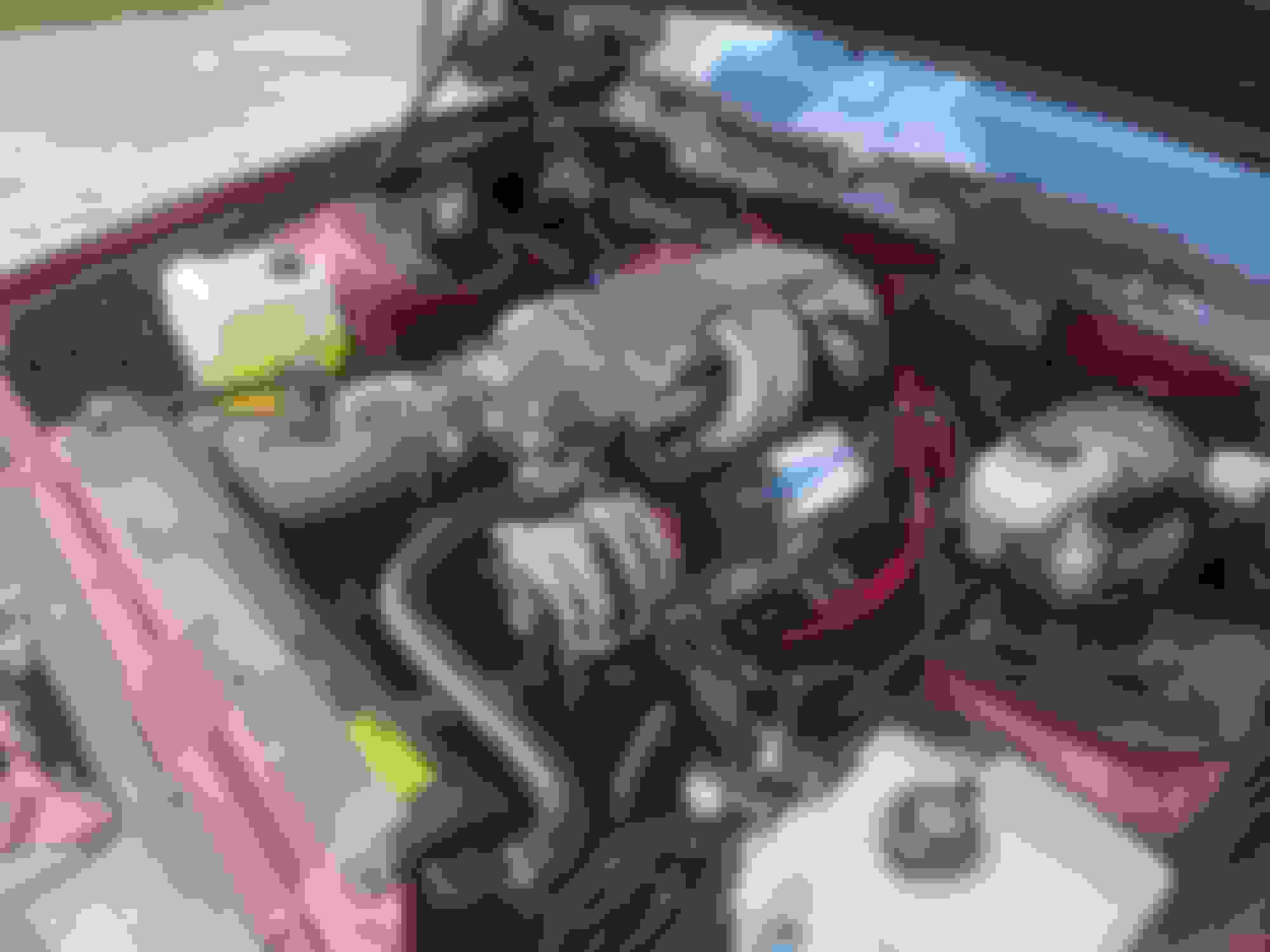
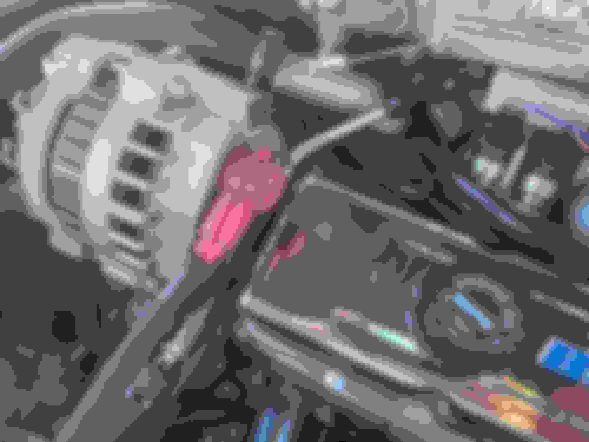
Another item i needed to modify was the existing alternator was not going to work. The battery terminal was in a position such that it was way to close to the larger blueprint valve covers. I basically "reclocked" the CS130 alternator by removing the pulley and the three alternator bolts on the circumference and rotating the position of the battery terminal. if you only slightly seperate the two halves of the alternator you can avoid having the brushes come off the armature and needing to go through a more involved process
Well my coolant weap / leak saga now extended to this setup over the last month with my Blueprint 383 / FIRST TPI install!
I noticed when looking underneath after driving a small wet smear on the ground that in the mornings ended up being a little bigger. Nothing gigantic, but also clearly not right.
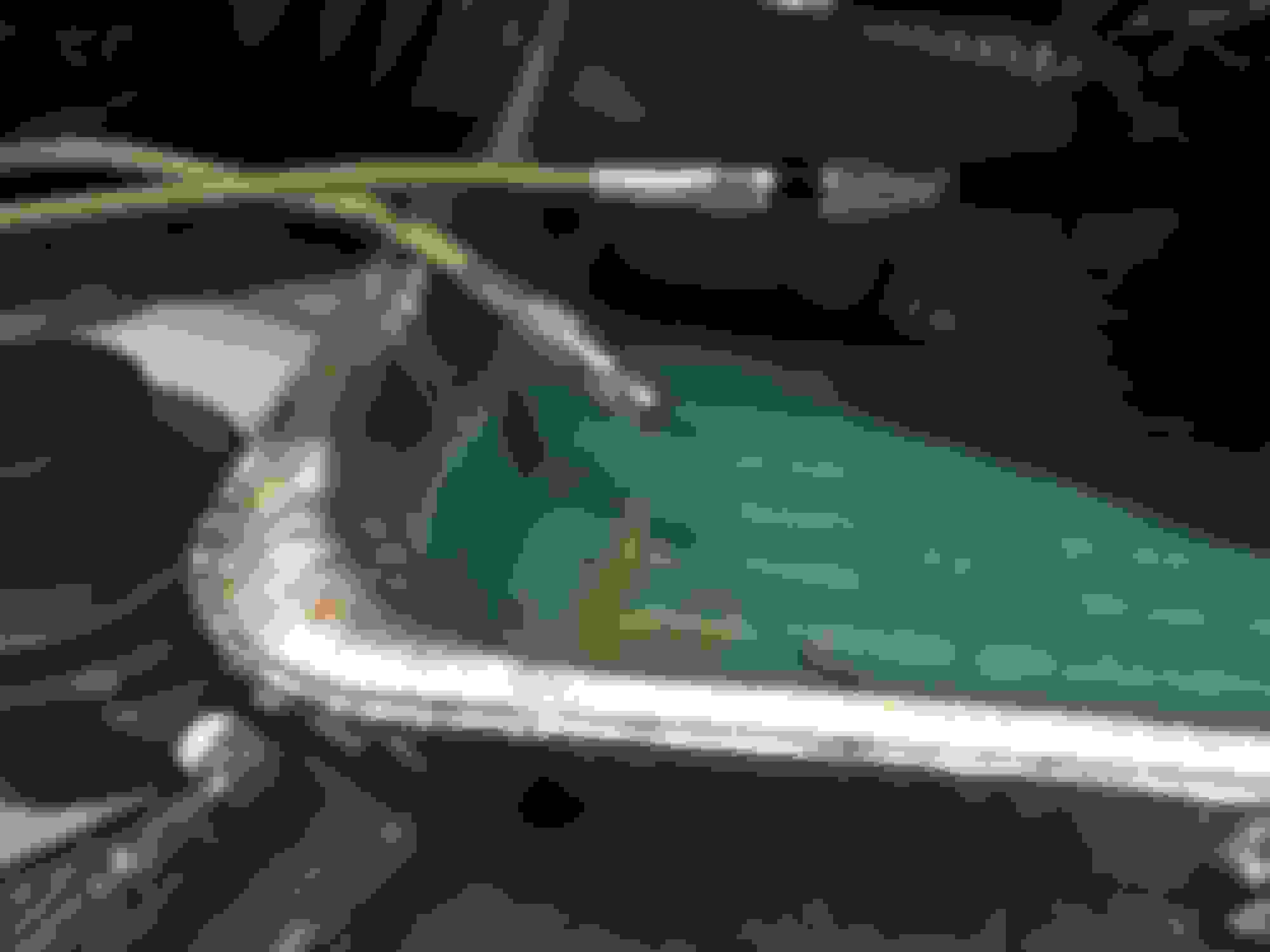
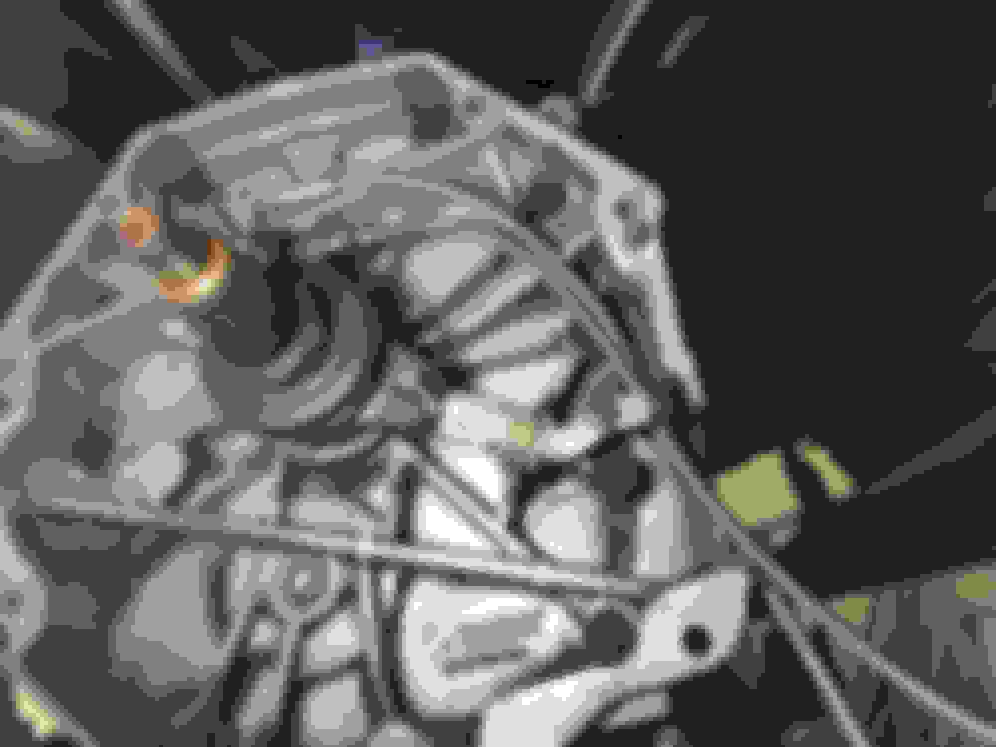
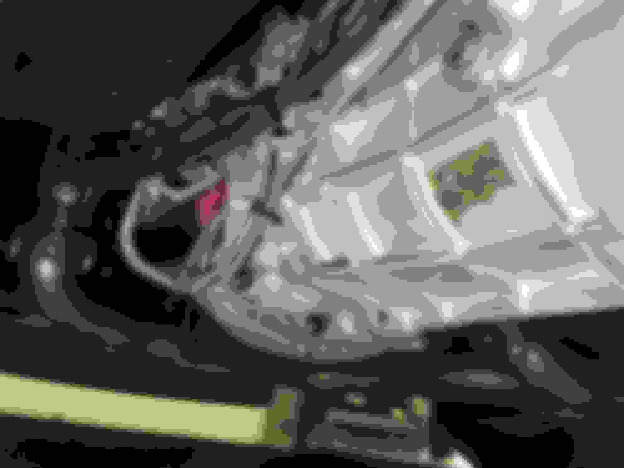
As you can see from the pictures the weap / leak was coming down the passenger rear block wall. It also was on the back of the bellhousing / engine block shelf and ultimately would make its way down to the starter and slowly cause drips to the gorund. If after the engine had cooled and the coolant pressure subsided i would wipe everything down no more weaping or dripping. However the next time I would take a drive it would be back. As it is very difficult to see behind the engine in that area i could not visually tell exactly where it was coming from, but obviously i suspected it was related to the rear water passage in the head / intake area. I had used my very successful gasket / red rtv sealing method on install but not sure what was going on.
As of course it is a little bit of a pain to take this intake all apart, i first tried some of those GM sealant tabs. Got the official GM ones from the dealer and gave it a shot, but after a week it hadn't made any difference so of course i would need to do something different
I have been talking to Ken a lot over the last month on possibilities of what is causing the leak.
upon dissasembly i inspected all the surfaces, gasket, etc as well as Ken through photos i sent, see photos below. Everything appeared to be sealed up well... of course with this type of issue that only appears when hot / pressurized and then stil just causes the slight dripping it is going to be something in the minor details likely
for this install, the Blueprint 383 utilizes basically their version of the GM Fastburn vortec type heads... the heads are drilled for the normal vortec 8 straight up/down bolts, but also the angled 12 intake bolts ... ken suggested and i agreed to have the FIRST intake made for the 12 angled bolts and Ken's normal supplied the 0.060 thick gaskets
One of my thoughts was that i had always utilized the 0.120 gasket on my projects with vortec heads / intakes, but of course this was with the normal vortec bolt pattern of the 8 bolts... i did try to line up the FIRST intake with a 0.120 gasket but the bolt pattern at that point didn't line up
I then sent the FIRST intake base back to Ken based on his adivce so he could check it. He has subsequently installed it on his test fit set up and hasn't found any issues. I had contimplated asking him just to revert the base to a standard vortec type mount and 0.120 gasket deck set up. Ken strongly advised not doing that based on his successful installs over the years, so for now he is just holding the base until I make up my mind.
In the meantime since it was hard to really trace were the weap / drip originated from, in hindsite i should have added some dye, I decided to install another vortec base to the set-up to help rule out anything other than the intake / intake install being the issue
The intake I chose to install at this point was an Edelbrock Pro-Flow XT. This intake is drilled for the standard vortec 8 bolt mounting pattern and utilizes the 0.120 thick intake gasket. For bolts i utilized the ARP vortec set and for the gasket i utilized Edelbrock's 7235 with permatex right stuff sealant on the china walls and water ports
The install was generaly very straight forward, I did need to grind some material of the intakes bolt mounting pad sides as the edges come squared off vs following the intake angle and wouldn't allow the intake to fully seat on the Blueprint heads
It took me the last month as I have been very busy at work, but I was able to get the Camaro with the Blueprint 383 w/Pro Flow XT fired up yesterday.
For the tune I utilized the same one I left off with the FIRST TPI as I am using the same base engine, injectors, etc as should be close enough.
After getting it started (first try!), confirming fuel pressure, timing, etc I needed to drill an idle air hole in the throttle blade as i couldn't get it to idle, have TPS correct, reasonable IAC count at warm idle, etc without some more base bleed air. I drilled a 5/32 hole (same as early LS1 throttle bodies) and likely need to go a little bit bigger, but it is close enough now for good driving without stalling, etc
I took it on first couple drives last night and so far no sign of any coolant weap, leak, drips as shown in pics! Will need to give it some more time, but hopefully have this one running as a good baseline i just need to polish the tune
I really like so far the Pro Flow XT. It is well made and all the supporting components fit well together, etc. Time will tell!
Over the last week i have been tuning and running with the new Pro Flow XT set up.
I took quite a bit of time in re-verifying the basics and actually spending more detailed time on the timing, VE, etc curves now that i haven't had to worry about weaping / leaking coolant at this point.
Couple of things
- Base Timing - with this 383 and set up, i ended up with 18 deg advance base timing to have reasonable start-up / warm idle with the EST on Bypass and spark only being controlled by the ICM
- VE maps - ended up doing a lot of WB VE learns over the last week and have some really solid maps at this point with this set-up and I am running well in all conditions in open loop. I probably have ~15 WB VE learns of 30-60 minutes each at all different conditions to get to this point
- I do have slight surging / lugging at < 2000 rpm < 15 % throttle... taking out some of the spark advance and getting the VE learns in good shape has helped this greatly, but some of that is still there. running open loop cruise right now with a slightly rich condition has also helped
more tuning to do, but EBL has been a great platform to work with
Over the last week i have been tuning and running with the new Pro Flow XT set up.
- I do have slight surging / lugging at < 2000 rpm < 15 % throttle... taking out some of the spark advance and getting the VE learns in good shape has helped this greatly, but some of that is still there. running open loop cruise right now with a slightly rich condition has also helped
more tuning to do, but EBL has been a great platform to work with
I have been working on this surging over the last week and made a lot of progress. The blueprint 383 has a relatively high overlap cam with 230 I / 236 E / 110 LSA which gives a 13 deg overlap and is challenging to the closed loop control in the cruise region, ie lower rpm / map / throttle ... what i ended up with at this point
- Open Loop Operation
- A lot of wide band work in this region to get general VE shape
- Good smoothing of the VE tables in this region to avoid sharp changes cell to cell
- Lowering spark advance in the cruise region to 30 deg
- Adjusted commanded open loop AFR through learning, commanding 14.4 now in the cruise area
I now have a very smooth cruising tune... i have occasionally some very slight surge still but hardly noticable and huge improvement from where i started
i have continued to work on this third gen to improve it and it is driving better and better, even now has a current PA state inspection!
over the last week i improved on the suspension with BMR's relatively new caster / camber plates that are nicely adjustable in a more predicatable way and did a good alignment. i also set the pinion angle correctly with an adjustable BMR torque arm install
The new caster / camber plates are BMR's WAK331... i actually like these even better than the Detroit Speed ones i have used on another build. They are a little lower profile and easier to get some negative camber on the driver side as you can get closer to the brake master with the lower profile. When I install these I put the bottom retainer plate fully to the rear and then just use the top to fine tune caster.
I also have koni adjustable shocks up front and UMI's weight jacks
I ended up setting my alignment with about 5 deg of caster, -0.3 deg of camber, and 3/32 toe in. I utilized my Truline TL-12 alignment tool and I can get a good alignment done myself in an afternoon on my lift. As part of this effort I also use an intercomp digital camber/caster gauge and intercomps caster plates
the other thing i did was go back to a traditional OEM style intermediate steering shaft. i had an expensive Detriot Speed shaft previously installed but honestly it never gave a great feel even with the nice Flaming River steering box i have on this camaro. The OEM type with good new rag joint seems to have the right balance of stiffness and still some compliance to give a good solid feel and no floaty feeling when on center
To set the pinion angle I use a digital angle gauge. You need to get three measurements with this.
- The transmission output shaft angle (get on transmission yoke or flat of tailhousing if known to be true to transmission output angle or on front engine balancer)
- The driveshaft angle
- The pinion angle (get on pinion yoke or flat of torque arm at diff)
You are looking to get the angle that is between the driveshaft and the transmission output shaft and compare it to the angle that is between the driveshaft and the pinion on the diff. generally you are wanting to get these to equal but opposite and then add a little more adjustment to compensate for the suspension wrap up that changes the pinion angle
Typically if your engine and transmission are mounted properly the output of the transmission will be about 3 deg down
Depending on your set up, the driveshaft will also be angling down, however in many cases of modified cars it can actually be sloping up. Think about how this affects the angles as you do your calculations... ie a sloping down driveshaft will reduce the overall operating angle between the transmission output and driveshaft. A sloping up driveshaft will increase the operating angle of the transmission and driveshaft. You want to also keep this operating angle reasonable... as it gets larger than 3 deg this itself can lead to vibration. You may need to think about shimming the transmission mount, etc. People tend to get confused on these angles when they are measured on what is positive / negative, just use common sense and think about what the angle is practically doing so you come up with a good result
To start, i measured my transmission output angle as 2.8 deg down, my driveshaft as 0.3 deg up, and my pinion as 1.3 deg up... That gave me an operating angle of 3.1 at the transmission and 1.6 at the pinion... not too bad actually, but i wanted to reduce the difference to only be about 0.5 to 1 deg as i have all poly bushings, etc. Utilizing the BMR adjustable torque arm, I made adjustments as appropriate to get the driveshaft angle to be about 2 deg up and i was good to go
Also just as a note, the torque arm I utlized, BMR MTA001 needed to be shortened at the front by about 1 inch to avoid hitting the speed sensor on the T-56
Those BMR strut plates are quite interesting looking. I have UMI ones and they come real close to the low fluid sensor on my brake fluid reservoir, but yours is way ahead of it and almost to the master cylinder. I'm running hydro boost though rather than a vacuum booster, but I didn't think it moved the M/C forward any.
Those BMR strut plates are quite interesting looking. I have UMI ones and they come real close to the low fluid sensor on my brake fluid reservoir, but yours is way ahead of it and almost to the master cylinder. I'm running hydro boost though rather than a vacuum booster, but I didn't think it moved the M/C forward any.
yes you can see earlier in the thread some pics with my prio UMI caster/camber plates... with the teeth on the bmr these are also much easier to adjust.and lock down position
yes you can see earlier in the thread some pics with my prio UMI caster/camber plates... with the teeth on the bmr these are also much easier to adjust.and lock down position
Ya my master cylinder is way further forward than yours, I haven't really seen anyone else using a 4th gen one, let alone with hydro boost. I can definitely see where having groved slots like that would be beneficial if you have setup changes in mind.