
Home brew road racer


Thread Starter
Senior Member

Joined: Aug 2007
Posts: 682
Likes: 45
Re: Home brew road racer
Here is an overhead view showing how everything is tying together, the radiator, fan and shroud, the side panels and center nose support.
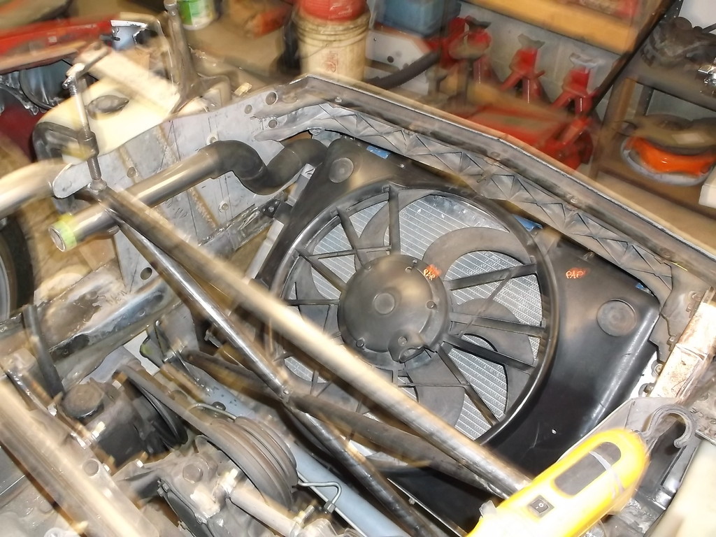
I could cover the x-brace with a thin aluminum sheet to help direct the air from the fan towards the hood and hope it goes out the extraction vent OR I could make a dedicated duct formed around the base of the fan and transitioning to a rectangle that would mate with the vent and force 100% of the air from the fan to go out the vent. More work but much more efficient.

I could cover the x-brace with a thin aluminum sheet to help direct the air from the fan towards the hood and hope it goes out the extraction vent OR I could make a dedicated duct formed around the base of the fan and transitioning to a rectangle that would mate with the vent and force 100% of the air from the fan to go out the vent. More work but much more efficient.


Junior Member
iTrader: (5)
Joined: Apr 2010
Posts: 7
Likes: 0
From: Seymour, IN
Car: 10 Camaro SS
Engine: Stock LS3
Transmission: TR6060
Axle/Gears: Factory LSD 3.45
Aero Opinion
Here is an overhead view showing how everything is tying together, the radiator, fan and shroud, the side panels and center nose support.

I could cover the x-brace with a thin aluminum sheet to help direct the air from the fan towards the hood and hope it goes out the extraction vent OR I could make a dedicated duct formed around the base of the fan and transitioning to a rectangle that would mate with the vent and force 100% of the air from the fan to go out the vent. More work but much more efficient.
I could cover the x-brace with a thin aluminum sheet to help direct the air from the fan towards the hood and hope it goes out the extraction vent OR I could make a dedicated duct formed around the base of the fan and transitioning to a rectangle that would mate with the vent and force 100% of the air from the fan to go out the vent. More work but much more efficient.
 The x-brace has made it a bit more difficult for continuous outlet ducting, but it's still workable. Taking a page out of the modern sports car racing playbook...and as you've said...your most efficient design (wrt downforce and cooling) will duct ALL of the air that passes through the radiator up and out of the top of the hood with a dedicated opening. IMO...pointing it towards a vent is better than nothing, but I'd recommend ducting it up and out.
 You can use this as inspiration:
http://www.motoiq.com/MagazineArticl...vette-C7R.aspx
Plenty of other pics out there.
Thread Starter
Senior Member
Joined: Aug 2007
Posts: 682
Likes: 45
Re: Aero Opinion
Lonewolf thanks for following along and the link. Not sure I am up to the C7R stage yet but always looking for ideas and motivation. I think the dedicated duct would be better but trying to keep it simple at the same time.
Thread Starter
Senior Member
Joined: Aug 2007
Posts: 682
Likes: 45
Re: Aero Opinion
Got a few small projects done over the weekend. Sometimes I wish I could just buy a part, take it out of the box and put it on the car. But then again where is the fun in that???
Got the headlights finally mounted in.Had to make sure each assembly was level and both units were level, same height, to each other. The APV lights have mounting holes bottom and top. Bottom brackets were simple 90 degree, slotted brackets from hardware store. Top brackets were made from .030 sheet steel.
original idea was to extend top bracket to front edge of hood to block air coming up and over headlight. Could still add this later.
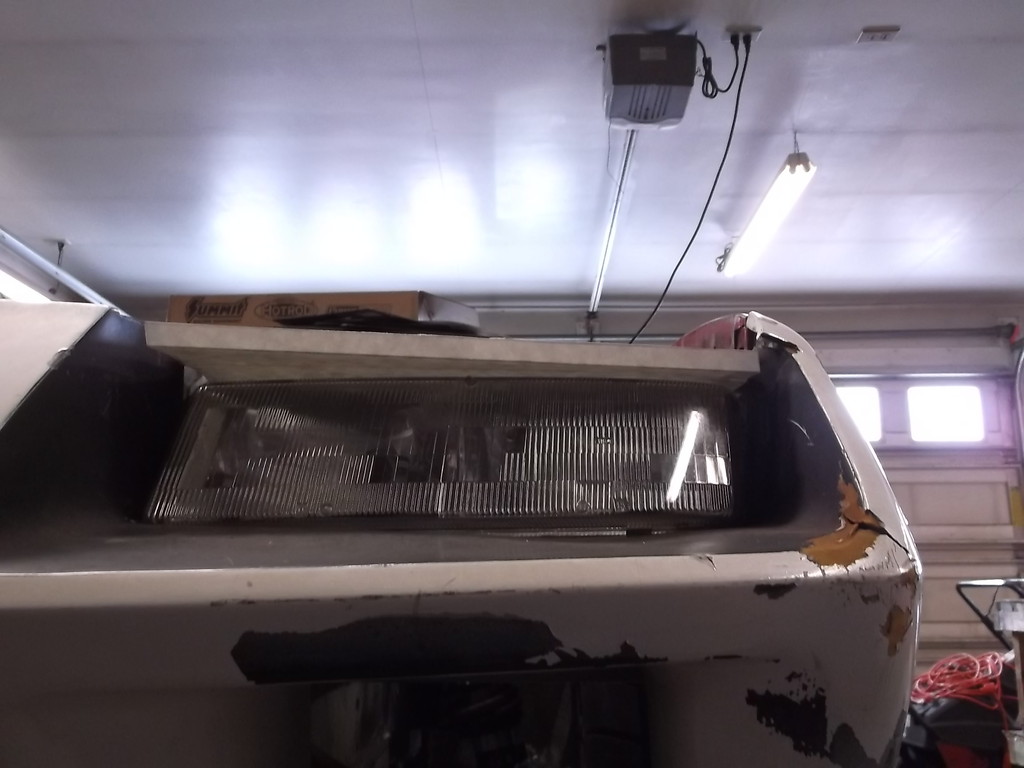
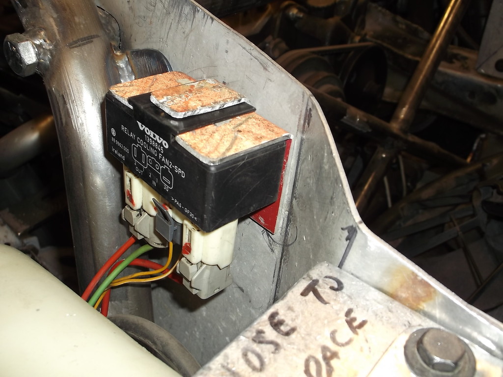
Made a bracket to mount fan controller. mounts behind right headlight.
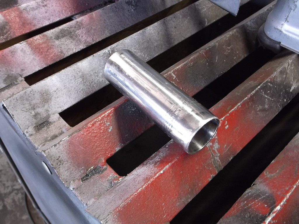
picked up a few parts at Summit to make up the radiator hoses. 1 1/2 diameter stainless U-bend, an inline remote fill pipe and 22lb radiator cap. I cut the u-bend into two 90 degree sections but needed to extend the short leg on both, 2" for the upper hose and for the lower hose 4".
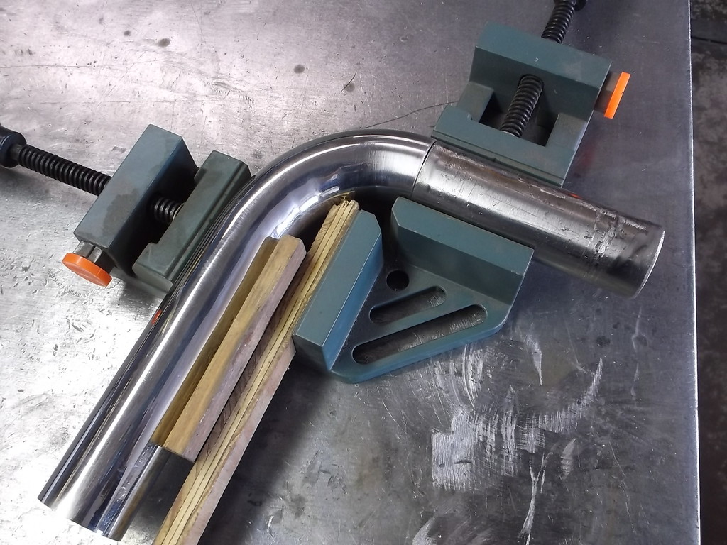
The upper hose I was able to cut off 2" from the long leg and weld it to the short side. To keep it all square I jigged it up in this harbour freight fixture.
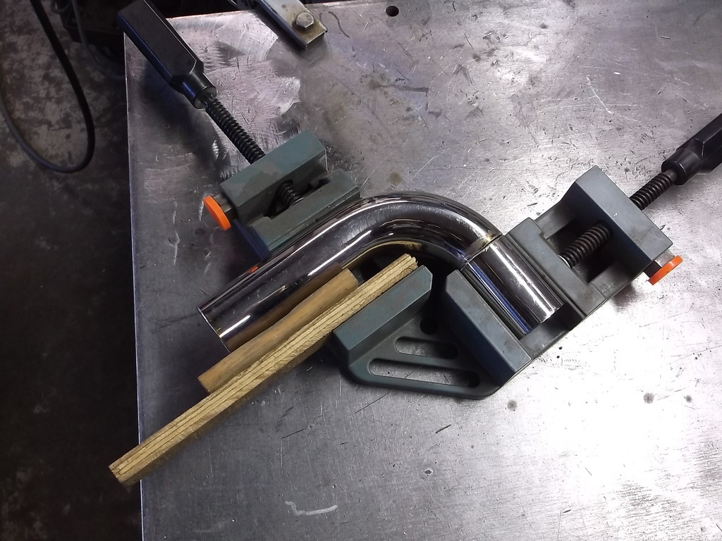
The piece for the lower hose required a 6" leg on one side of the bend and a 4" leg on the other. Not complicated except I didn't have any 1 1/2" tubing stainless or otherwise. I did however have a long pice of 304 stainless 4.5 wide and .120 thick. For some reason I thought I could use this and form my own tubing from flat sheet.
Bending the sheet around a piece of 1 5/8 tubing and then pressing it into a piece of heavy wall 1 3/4 tubing to use as a die it came out pretty good.
Got the headlights finally mounted in.Had to make sure each assembly was level and both units were level, same height, to each other. The APV lights have mounting holes bottom and top. Bottom brackets were simple 90 degree, slotted brackets from hardware store. Top brackets were made from .030 sheet steel.


original idea was to extend top bracket to front edge of hood to block air coming up and over headlight. Could still add this later.


Made a bracket to mount fan controller. mounts behind right headlight.

picked up a few parts at Summit to make up the radiator hoses. 1 1/2 diameter stainless U-bend, an inline remote fill pipe and 22lb radiator cap. I cut the u-bend into two 90 degree sections but needed to extend the short leg on both, 2" for the upper hose and for the lower hose 4".
The upper hose I was able to cut off 2" from the long leg and weld it to the short side. To keep it all square I jigged it up in this harbour freight fixture.

The piece for the lower hose required a 6" leg on one side of the bend and a 4" leg on the other. Not complicated except I didn't have any 1 1/2" tubing stainless or otherwise. I did however have a long pice of 304 stainless 4.5 wide and .120 thick. For some reason I thought I could use this and form my own tubing from flat sheet.
Bending the sheet around a piece of 1 5/8 tubing and then pressing it into a piece of heavy wall 1 3/4 tubing to use as a die it came out pretty good.


Thread Starter
Senior Member
Joined: Aug 2007
Posts: 682
Likes: 45
Re: Home brew road racer
lower hose looks like this now.
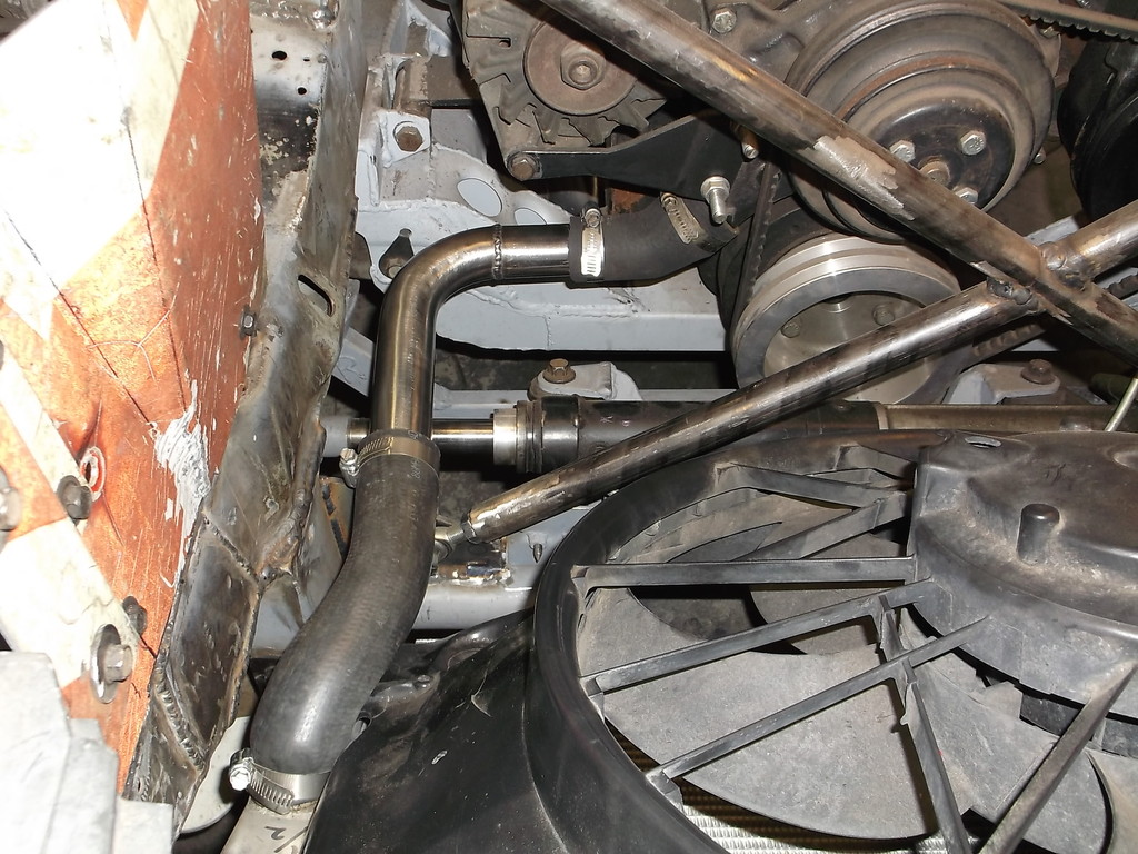
clears steering linkage
I realized that I needed to get the radiator cap above thermostat housing so had to reroute hose above the x-brace.
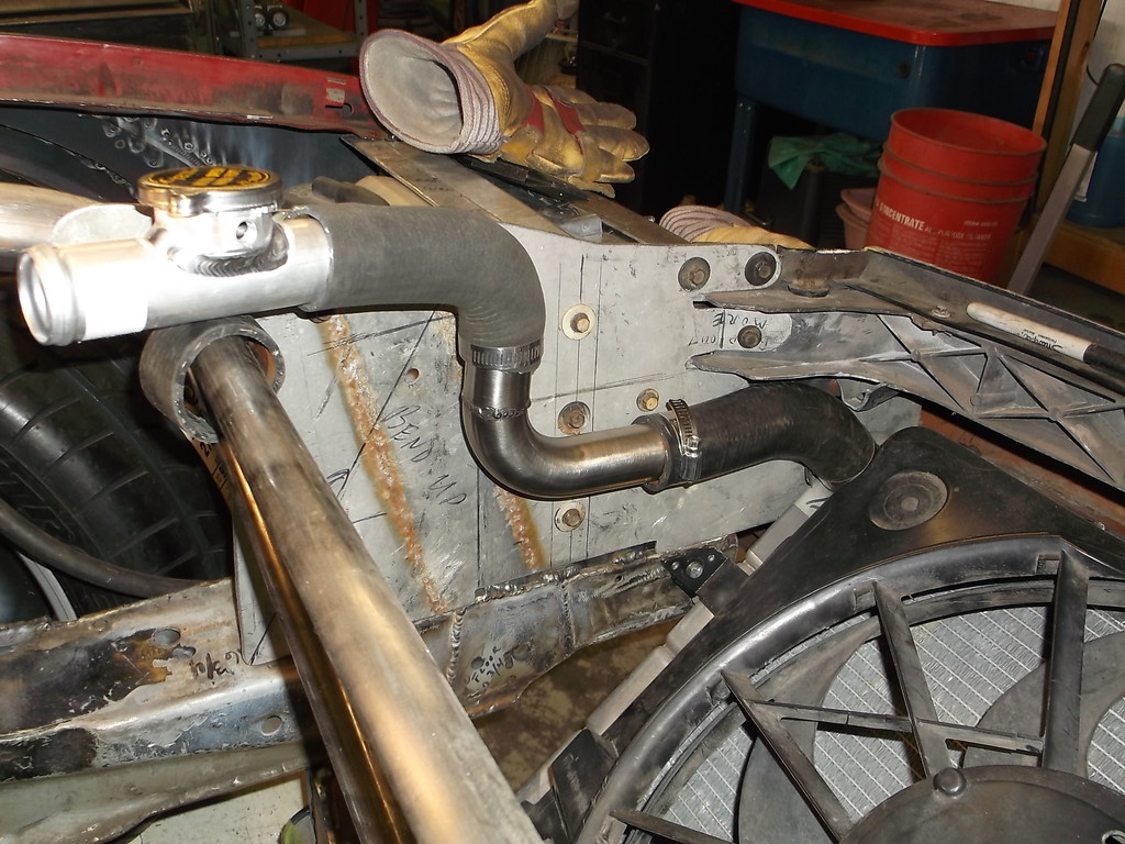
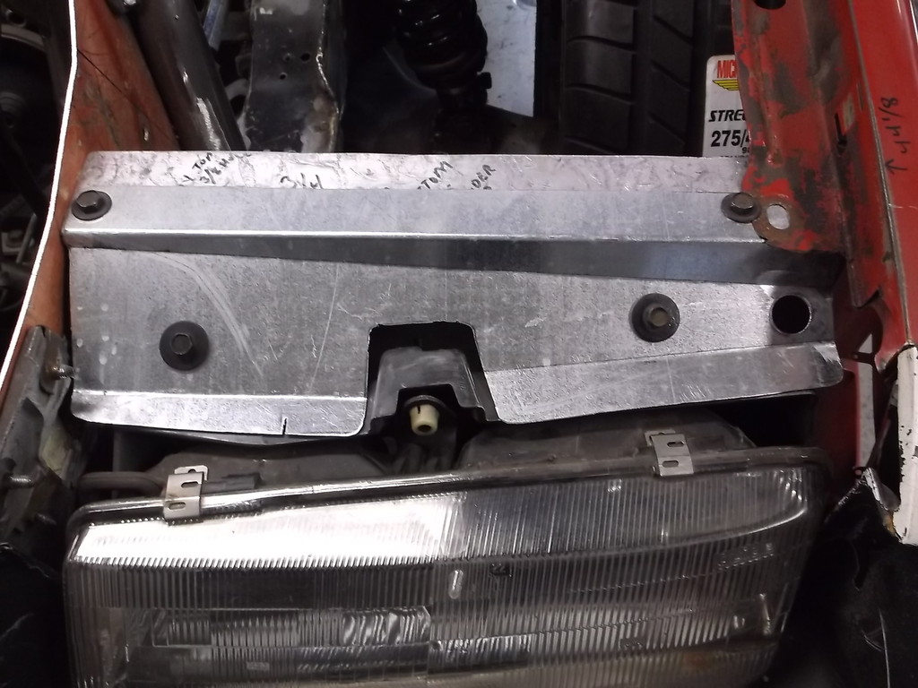
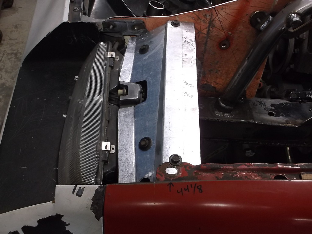
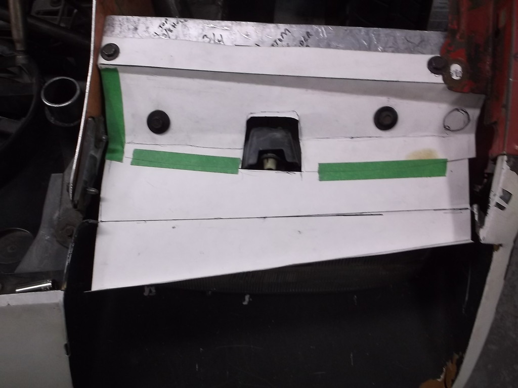
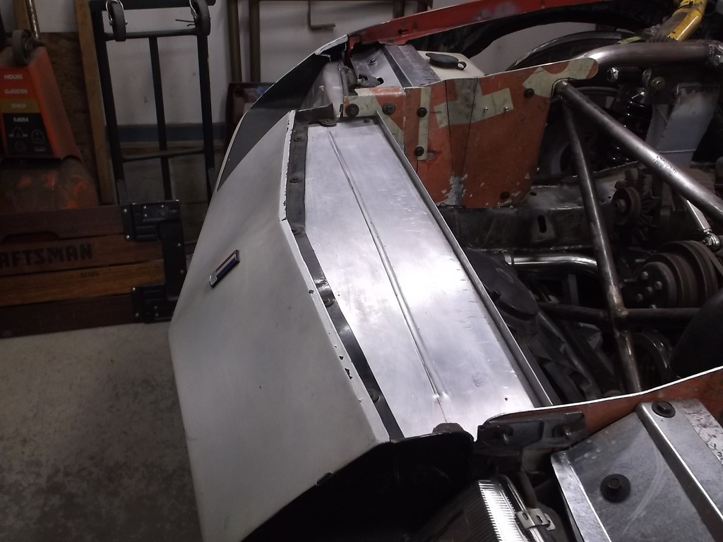
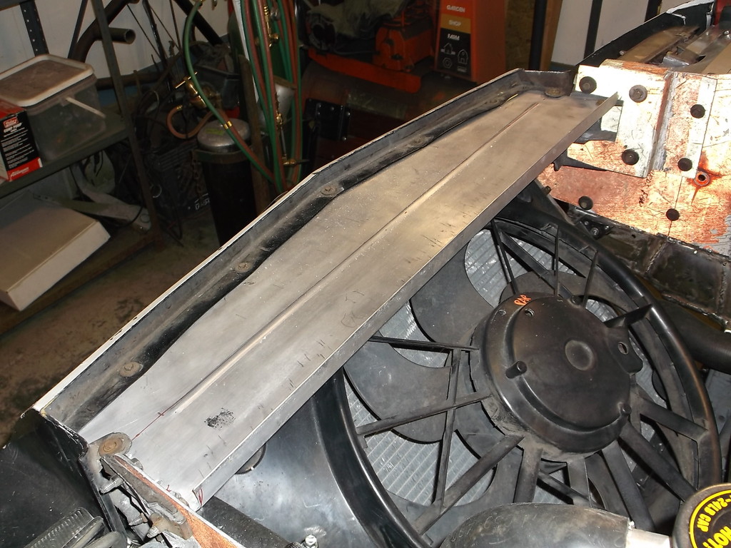
Last project was to make a panel fit above the fan. I really missed having a tray to lay tools and parts on. it will also keep hands and small items from getting into fan and radiator.
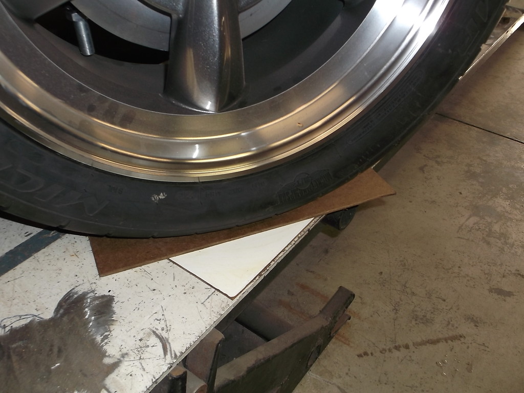
I didn't take any pictures but also mounted the washer resevoir and radiator recovery tank in behind the headlights. I did not think that there would be room but both clear the tires at full lock with room for suspension travel. These items were from my 95 C1500 truck I scrapped out a few years ago.
With the weight of the car resting on the wheels now I needed something that would allow me to turn the front wheels easily so I could check for clearances. I made some low buck turn plates using leftover pieces of dry erase paneling. Pieces are 12 x 14 and have a thin coat of chassis grease spread between them. I can turn the wheels one handed lock to lock with these. They work great for checking caster and setting toe as well.
When I first put the car back on its wheels one of the first things I did was to get accurate ground clearance measurements. Having to lower the engine an inch to fit in the TKO trans had me worried. Yes the engine is too low. The headers and bellhousing have less than 3" clearance. I am thinking I will raise the engine and trans 1 1/2 to 2". To do this I will need to cut out the trans tunnel pretty much front to back, rework the engine mounts (again) and probably fab up a new trans x-member.
I want to do this with the 383 engine and all the correct driveline parts in place so everything can get finalized. I mocked this up with the 700R4 in place and now it has come back to bite me. I need to finish up the front end before I pull the motor back out so next up is to make the tubular front bumper.

clears steering linkage

I realized that I needed to get the radiator cap above thermostat housing so had to reroute hose above the x-brace.

Last project was to make a panel fit above the fan. I really missed having a tray to lay tools and parts on. it will also keep hands and small items from getting into fan and radiator.


I didn't take any pictures but also mounted the washer resevoir and radiator recovery tank in behind the headlights. I did not think that there would be room but both clear the tires at full lock with room for suspension travel. These items were from my 95 C1500 truck I scrapped out a few years ago.
With the weight of the car resting on the wheels now I needed something that would allow me to turn the front wheels easily so I could check for clearances. I made some low buck turn plates using leftover pieces of dry erase paneling. Pieces are 12 x 14 and have a thin coat of chassis grease spread between them. I can turn the wheels one handed lock to lock with these. They work great for checking caster and setting toe as well.

When I first put the car back on its wheels one of the first things I did was to get accurate ground clearance measurements. Having to lower the engine an inch to fit in the TKO trans had me worried. Yes the engine is too low. The headers and bellhousing have less than 3" clearance. I am thinking I will raise the engine and trans 1 1/2 to 2". To do this I will need to cut out the trans tunnel pretty much front to back, rework the engine mounts (again) and probably fab up a new trans x-member.
I want to do this with the 383 engine and all the correct driveline parts in place so everything can get finalized. I mocked this up with the 700R4 in place and now it has come back to bite me. I need to finish up the front end before I pull the motor back out so next up is to make the tubular front bumper.
Thread Starter
Senior Member
Joined: Aug 2007
Posts: 682
Likes: 45
Re: Home brew road racer
My friend that owns the engine shop where I built my 383 at got real sick just before xmas and was hospitalized for 60 days!!! He needed someone to stay with him once he got home to help him get back on his feet. I volunteered and spent the last two weeks staying at his house, basically being a live-in aide. He was pretty shaky at first but got stronger every day. When I left him this past Friday he was doing pretty well.
I will be getting back to work on the Camaro tomorrow, getting the tubing to make the front bumper and starting on that project. Plans are to have it fired up by late April and road worthy by late June. Thats the plan but we all know life has a way of interupting our play time.
I will be getting back to work on the Camaro tomorrow, getting the tubing to make the front bumper and starting on that project. Plans are to have it fired up by late April and road worthy by late June. Thats the plan but we all know life has a way of interupting our play time.
Thread Starter
Senior Member
Joined: Aug 2007
Posts: 682
Likes: 45
Re: Home brew road racer
Got the bumper and mounts finally made. It is basically 1 5/8 x .120 wall roll bar tubing fitted inside the front valance just above the grille and parking lights. I would have gone bigger on the tubing, but 1 5/8 fit the space just right. The two strut bars that attach it to the frame are same tubing. Front of factory frame rails were reinforced 1st with 1/8 sheet steel and then added 1/4" plate. Front of frame horn was capped with 1/4" plate also.
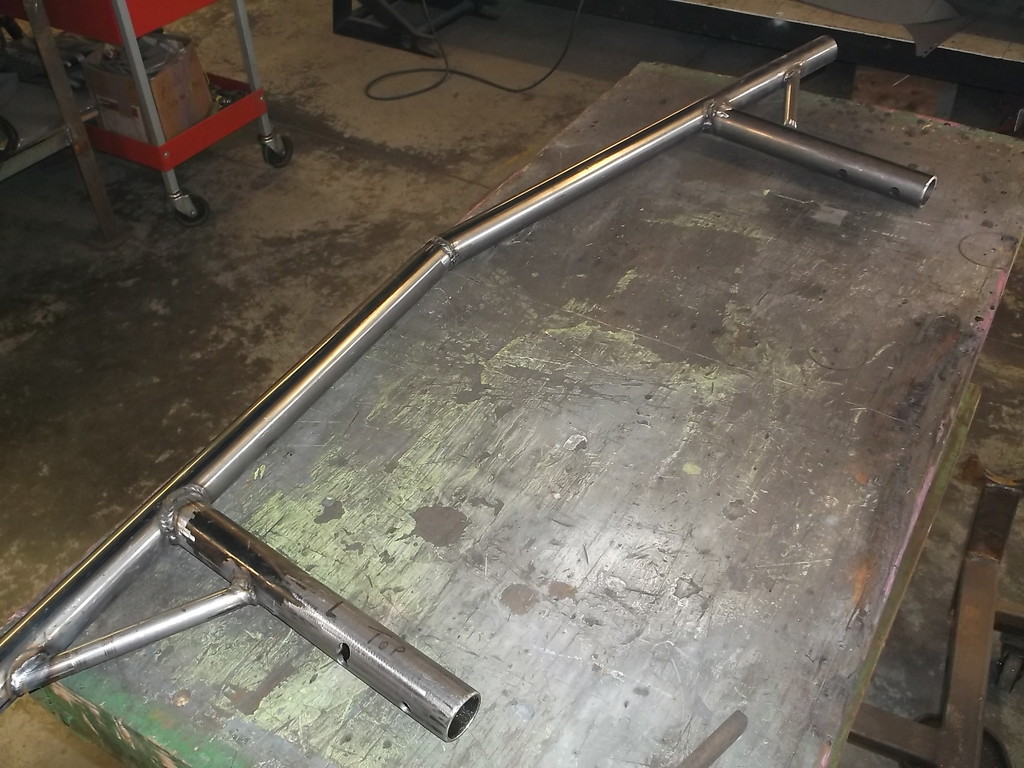
1 5/8 fits nice and snug between headlight and parking light openings.
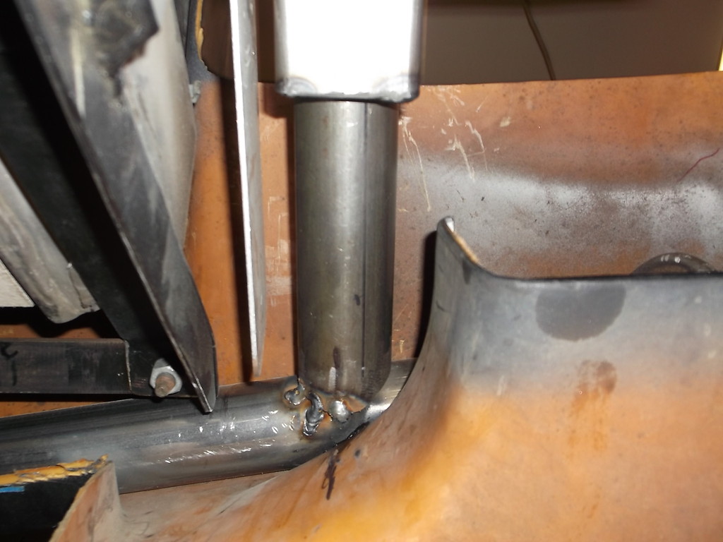
Radiator mount is less than 1" behind bumper. Radiator bracket is to left.
Reinforced and capped frame horns
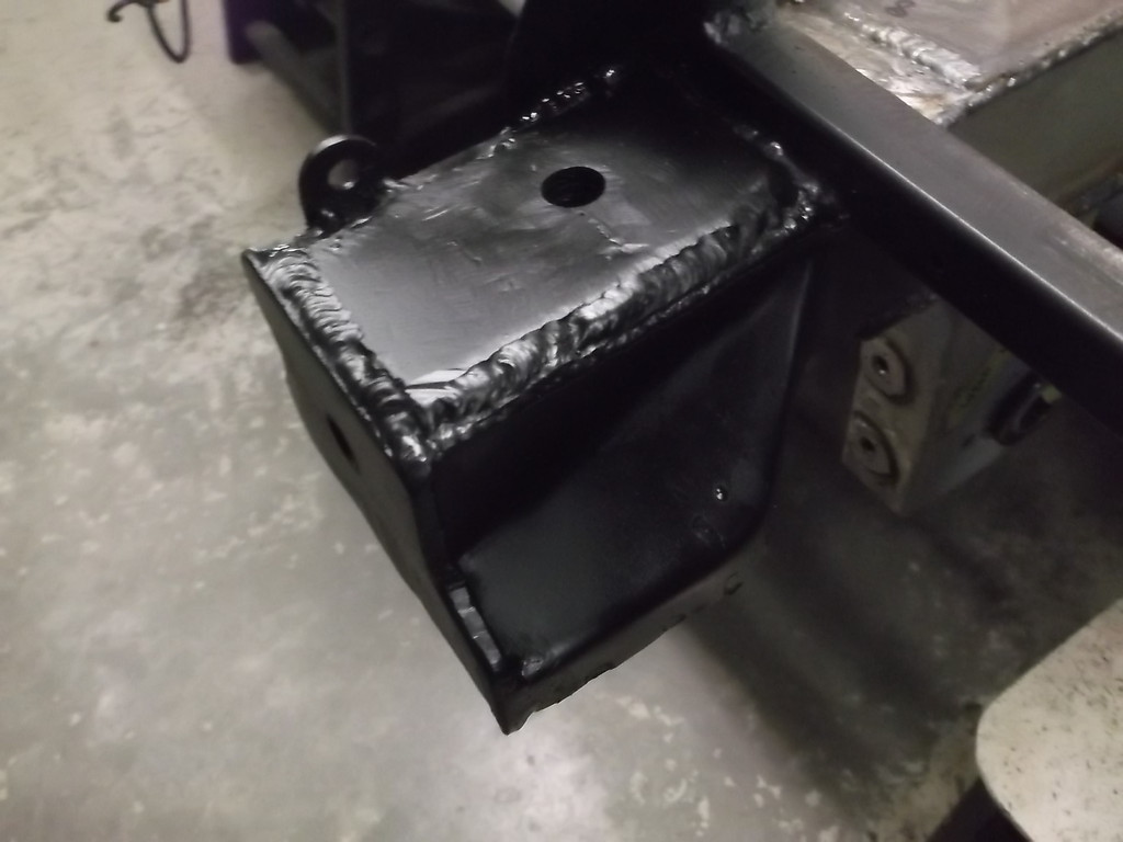
Bumper mount brackets are 2 x 2 x .120 square tube with top side cut out. This let the square tubing pull down tight to the 1 5/8 tubing with the two 1/2" bolts.
To get the strut bars level from bumper to frame I had to build up the frame end about 3/4". That is the reason for the 1/4" plate and the 3/8 bolts welded into the 2 x 2.
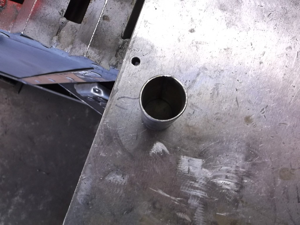
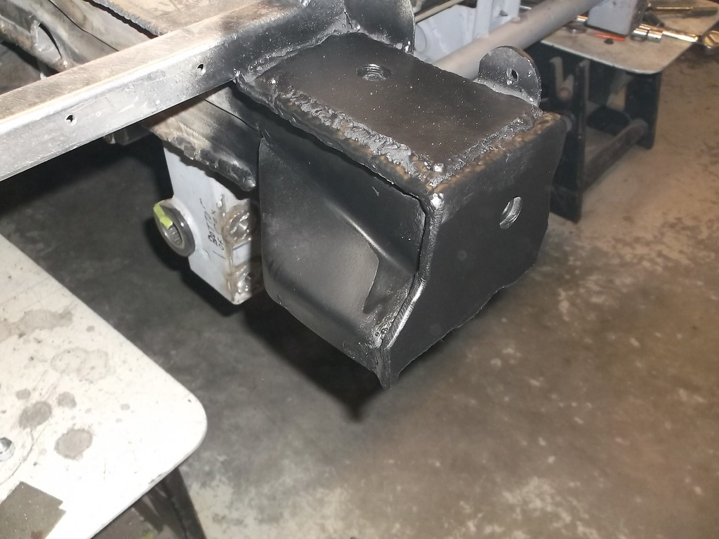
The bumper mounts to the 2 x 2 with two 1/2" bolts. The 2 x 2 mounts to the frame with one 1/2" bolt down through the frame rail and one 1/2" bolt bolted through the capped frame horn.
Large hole in bottom gives access to rear bolt.
Good shot of how it all fits together

1 5/8 fits nice and snug between headlight and parking light openings.

Radiator mount is less than 1" behind bumper. Radiator bracket is to left.

Reinforced and capped frame horns


Bumper mount brackets are 2 x 2 x .120 square tube with top side cut out. This let the square tubing pull down tight to the 1 5/8 tubing with the two 1/2" bolts.

To get the strut bars level from bumper to frame I had to build up the frame end about 3/4". That is the reason for the 1/4" plate and the 3/8 bolts welded into the 2 x 2.
The bumper mounts to the 2 x 2 with two 1/2" bolts. The 2 x 2 mounts to the frame with one 1/2" bolt down through the frame rail and one 1/2" bolt bolted through the capped frame horn.

Large hole in bottom gives access to rear bolt.

Good shot of how it all fits together

Thread Starter
Senior Member
Joined: Aug 2007
Posts: 682
Likes: 45
Re: Home brew road racer
Tex thanks for looking in and the kind words. I was trying to keep the bumper simple in construction, but relatively strong ( I know my radiator is toast in any kind of front collision harder than a love tap) and easy to remove. This would be a great design for a drag car or a track only road race car. This car will see a couple thousand street miles a year so maybe not as strong as it should be.
The ultimate plan for this is to have the front valance bolted to the tubular bumper so that they both can come off together. In my head I have the 5 front valance to fender bolts on each side converted to locating pins and the valance held tight to the fenders with some type of snap-over-center quick latch. Then the bumper/valance unbolts with a total of just 8 easily accessible bolts, about 5 minutes to remove.
The bumper is pretty simple right now. Future plans call for some 1" or 1 1/4" down tubes coming off the mounting tubes and maybe a 1x1 square tube lower bumper. I want to be able to bolt up an aluminum splitter and the extra frame work would give me mounting options as well as protecting the bottom of the valance.
Thread Starter
Senior Member
Joined: Aug 2007
Posts: 682
Likes: 45
Re: Home brew road racer
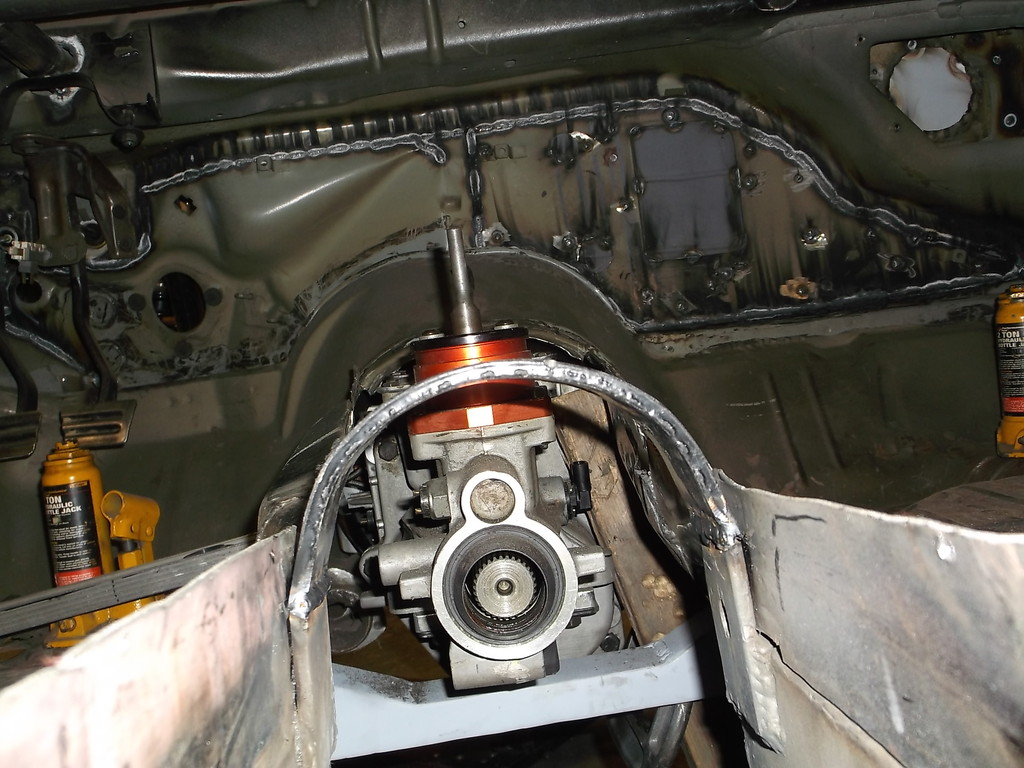
Propaint, probably not till June at least. I am having to redo the engine and trans mounts and cut out and remake the tunnel. All of this was based around the 700R4 and I had major driveline alignment issues once the TKO600 was put in. I corrected the alignment by lowering the engine 1" and raising the trans mount 1/2" but that left the headers and Lakewood bellhousing only 2" off the ground.
I have just pulled the engine and TKO back out of the car and have started to cut out the tunnel. Once that is cut out I will put together the actual engine/clutch/trans package that I will be using along with the headers and get it all repositioned in the car. I am hoping to get everything raised up 1 1/2 to 2" from where it is now to maximize the ground clearance. I may very well have to completely redesign the engine mounts and the trans crossmember.
One other problem caused by using the 700R4 for mock up is not having room to remove the TKO from under the car with the engine bolted in place. With the 700R4 I did not have to account for the extra length of the TKO input shaft having to clear the Lakewood bellhousing. As it is I lack about 2" with the trans tailshaft hitting my middle crossmember. I can't move the crossmember back but I can make the center section removable to get the needed room.
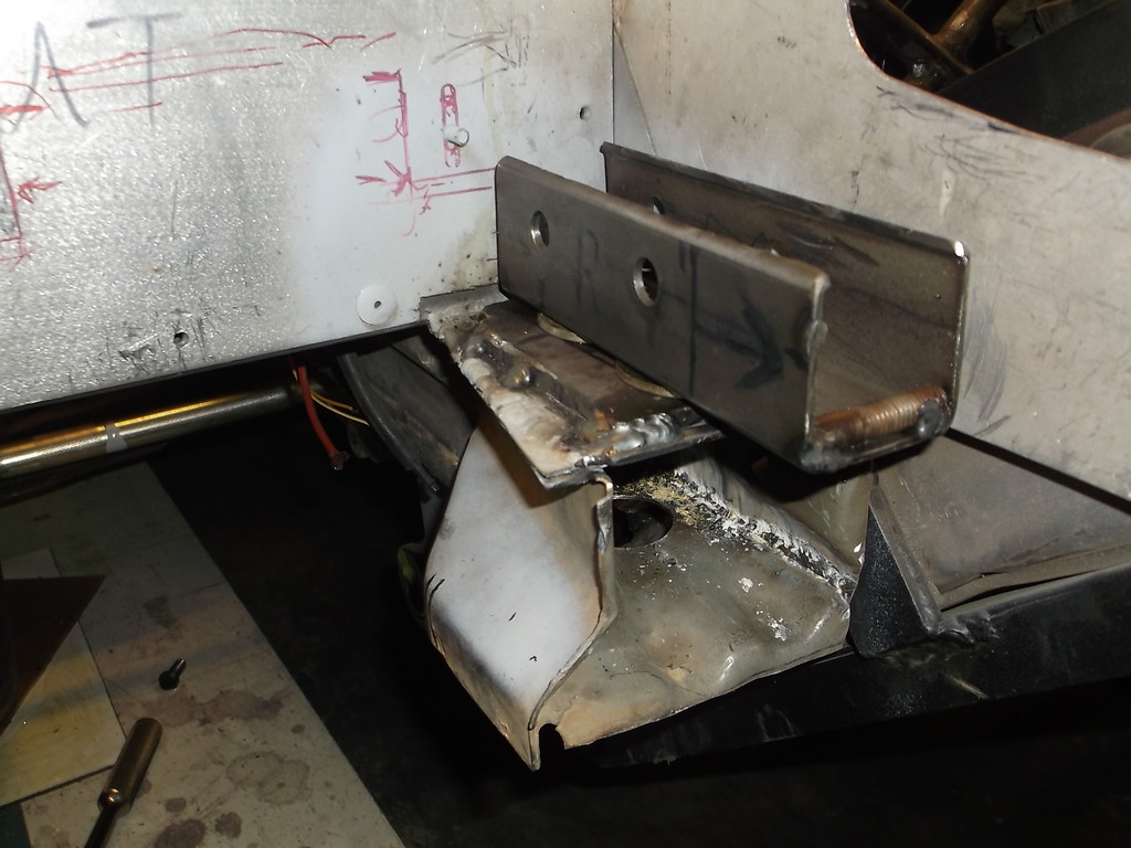
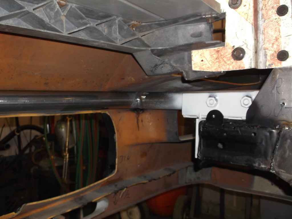
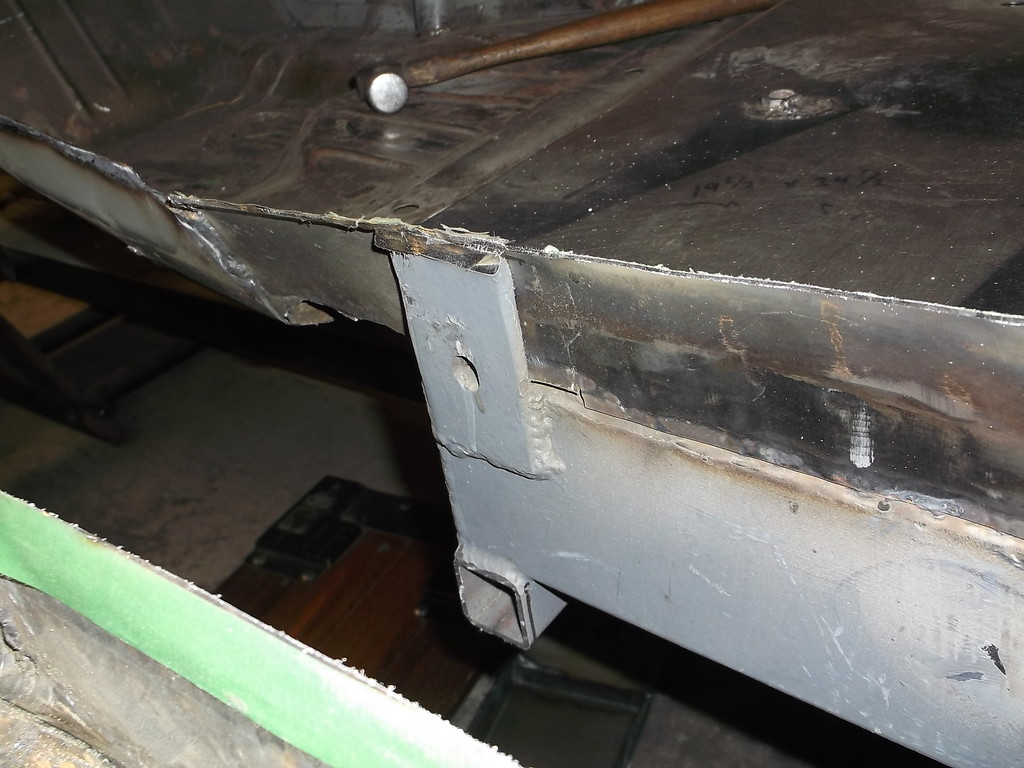
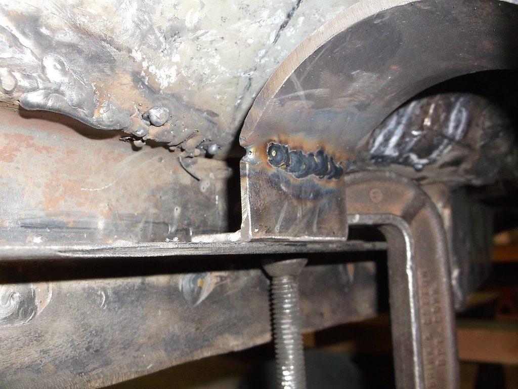
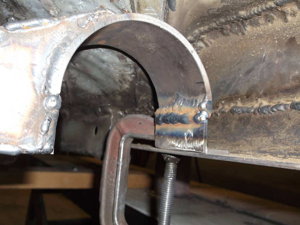
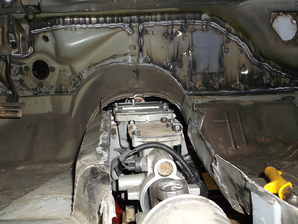
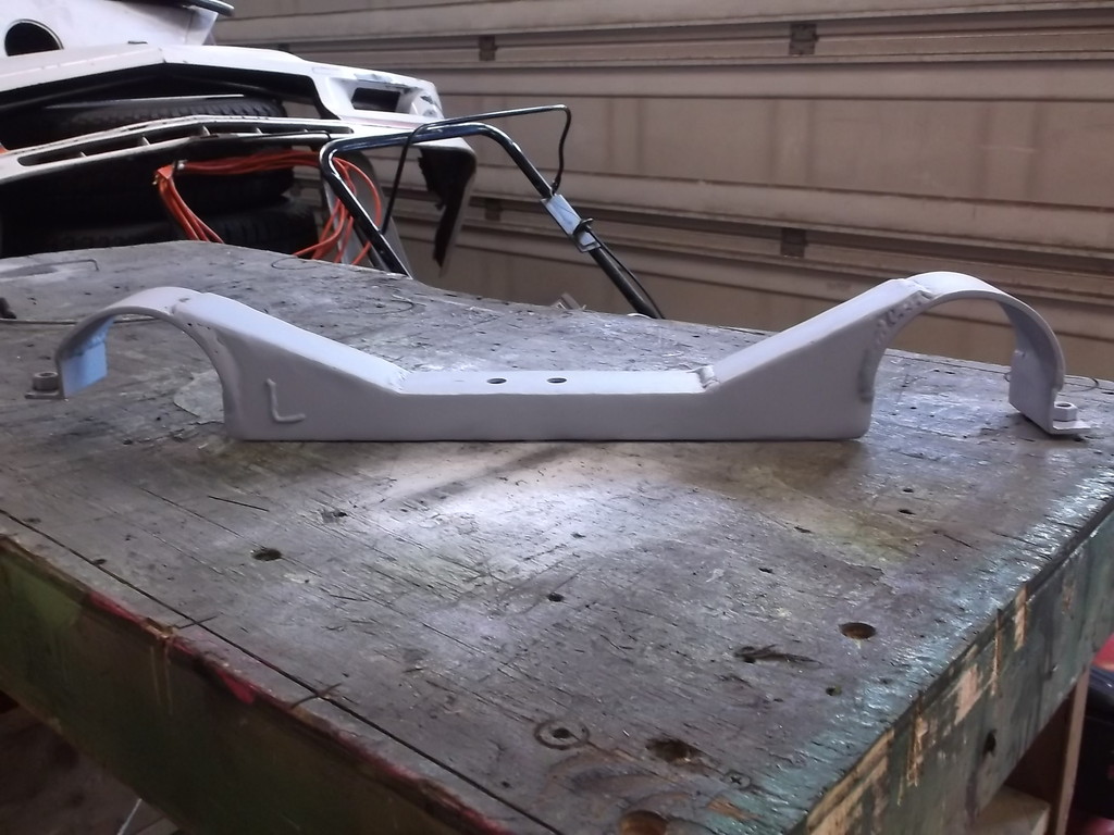
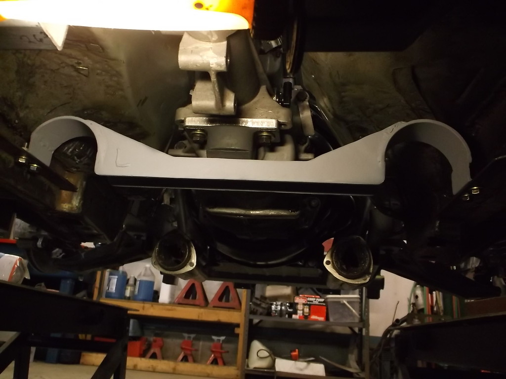
This is the middle crossmember.
I purposely welded the section of 1.5 x 1.5 square tubing along the bottom to help maintain lateral strength. I will have to cut this out for trans clearance. I will also have to cut out the 1/4" plate that makes up the top of my driveshaft loop to raise the tunnel. I will probably have a heavy wall, 1 1/2" tube bent into a "U" shape to replace the top half and make removable section for the bottom.
This was one of the few times I designed/built something for this car without having the actual part being used on hand and it has come back to bite me big time. See what you caused by selling me the TKO?
I have just pulled the engine and TKO back out of the car and have started to cut out the tunnel. Once that is cut out I will put together the actual engine/clutch/trans package that I will be using along with the headers and get it all repositioned in the car. I am hoping to get everything raised up 1 1/2 to 2" from where it is now to maximize the ground clearance. I may very well have to completely redesign the engine mounts and the trans crossmember.
One other problem caused by using the 700R4 for mock up is not having room to remove the TKO from under the car with the engine bolted in place. With the 700R4 I did not have to account for the extra length of the TKO input shaft having to clear the Lakewood bellhousing. As it is I lack about 2" with the trans tailshaft hitting my middle crossmember. I can't move the crossmember back but I can make the center section removable to get the needed room.
This is the middle crossmember.

I purposely welded the section of 1.5 x 1.5 square tubing along the bottom to help maintain lateral strength. I will have to cut this out for trans clearance. I will also have to cut out the 1/4" plate that makes up the top of my driveshaft loop to raise the tunnel. I will probably have a heavy wall, 1 1/2" tube bent into a "U" shape to replace the top half and make removable section for the bottom.
This was one of the few times I designed/built something for this car without having the actual part being used on hand and it has come back to bite me big time. See what you caused by selling me the TKO?
Thread Starter
Senior Member
Joined: Aug 2007
Posts: 682
Likes: 45
Re: Home brew road racer
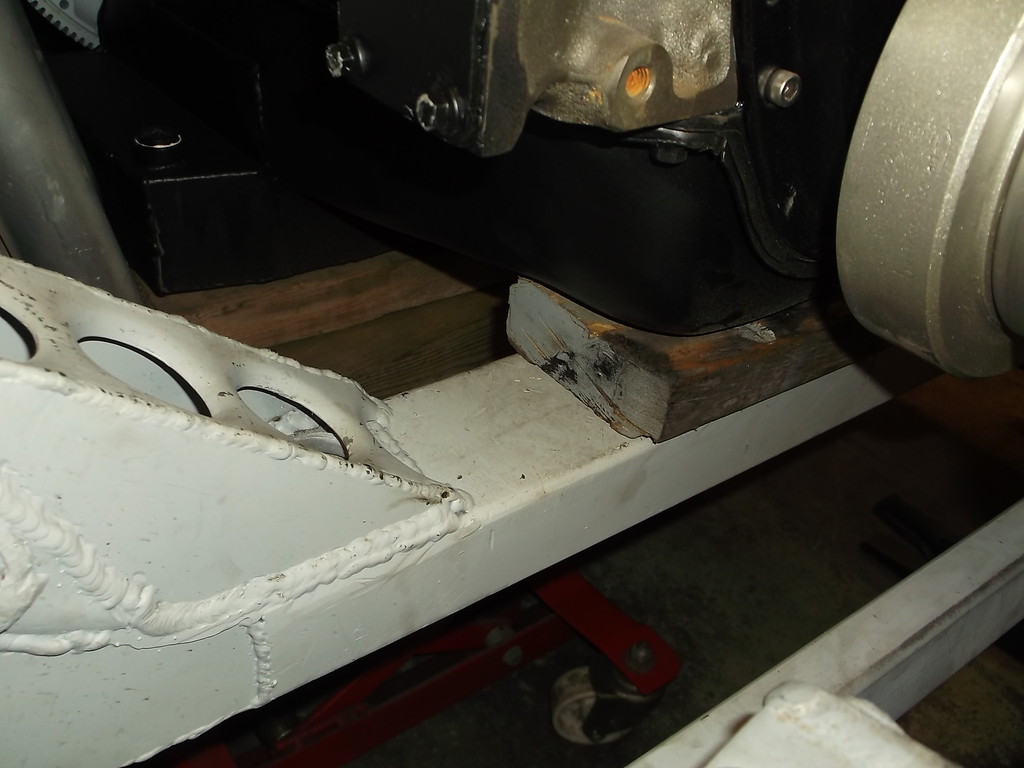
Ok so not happy about having to cut out the tunnel and redo.
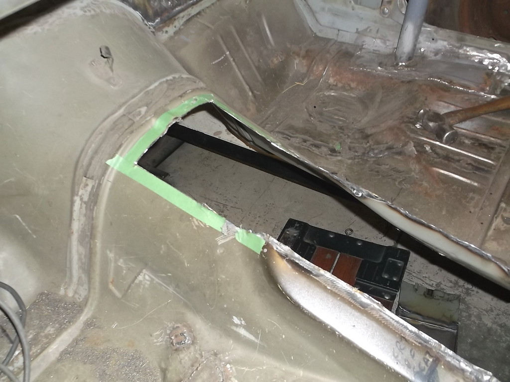
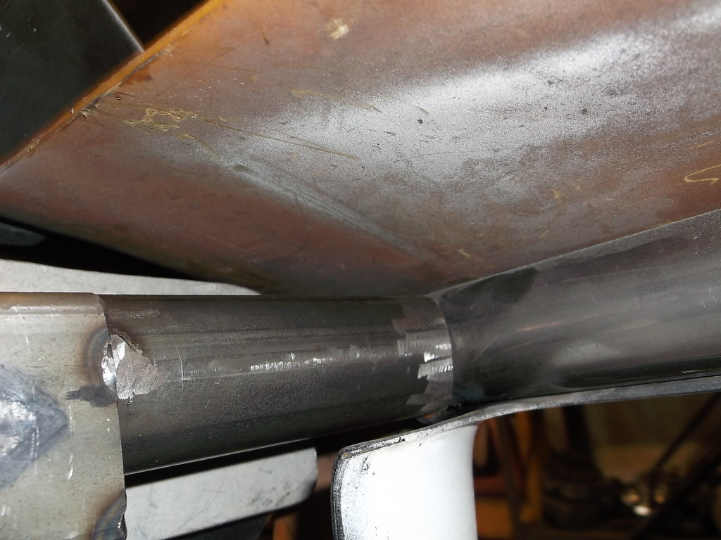
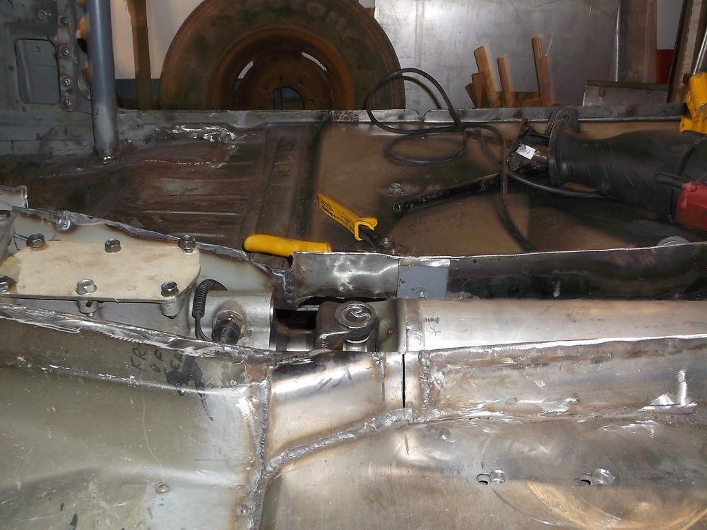
In this pic you can see where I had to cut out the welded in, non-removable driveshaft loop. I will make the lower part a bolt-in affair and the top 1/4 x 2" strap piece wil be raised and formed into a more round hoop shape as the new tunnel will have a more conventional rounded top.
Before I can redo the trans tunnel I have to remount the engine/trans in its new, higher location. To make sure I get it right this time I wanted to have the correct engine, oil pan. headers, etc. in place so I know everything fits and I have the correct drive line angles.
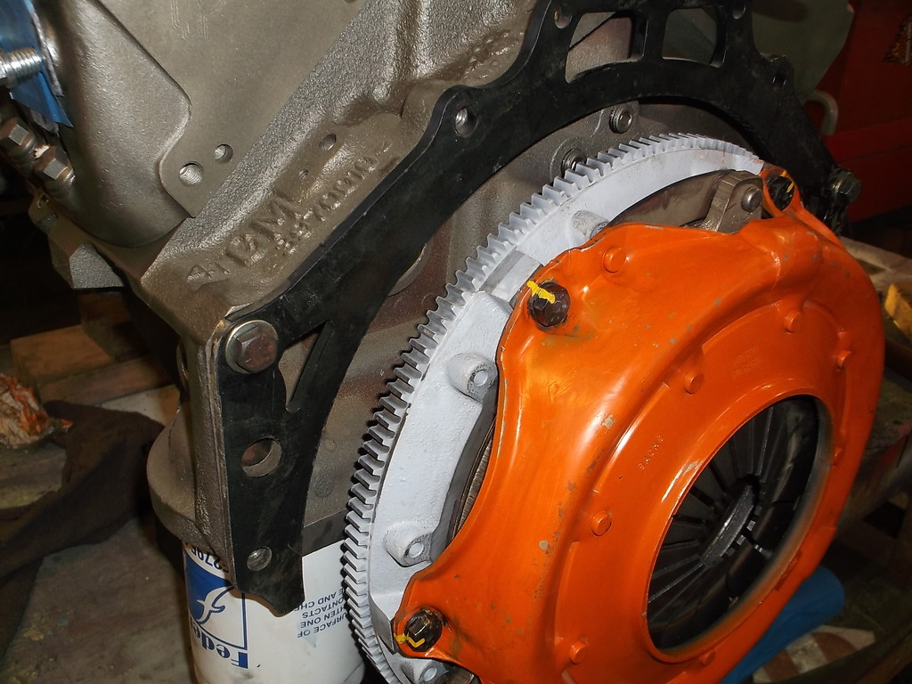
I am using the Mc Leod bolt on hydraulic throwout bearing assembly that replaces the front bearing support on the TKO 600. This unit utilizes a constant running bearing, meaning it is always in contact with the fingers on the pressure plate. Because of this, the distance between the pressure plate fingers and the back face of the bellhousing is critical. In order for me to get the proper distance I had to utilize the 1/4" thick steel mid plate that I have shown in earlier posts. I wasn't going to use this as the mounting ears make it nearly impossible to install the headers. I went ahead and cut the ears off so the mid plate is flush to the block. I will tack weld the mid plate to the Lakewood bellhousing so that I am not trying to juggle two pieces when installing the trans.
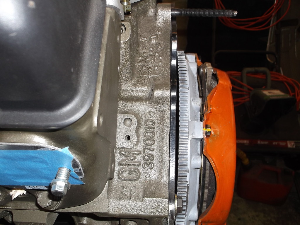
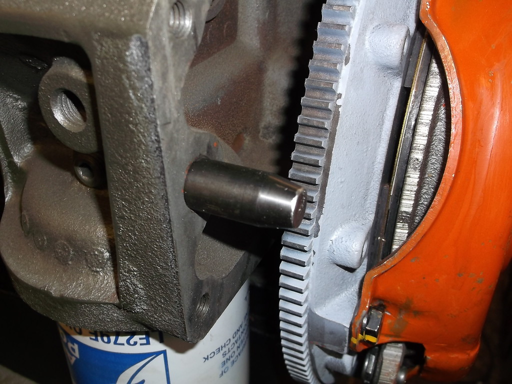
Because of the extra 1/4" of the mid plate I had to use extra long dowel pins and an extended pilot bearing. The dowel pins were from TCI and the pilot bearing was from Allstar.
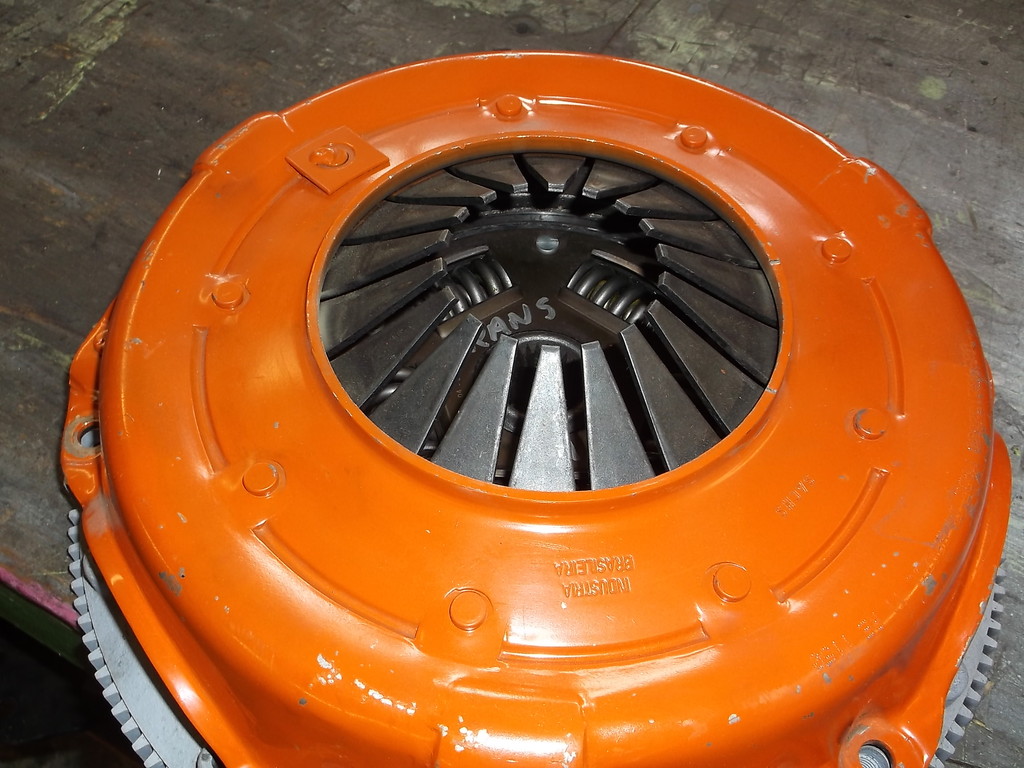
I am using the Centerforce dual friction clutch which is not compatible with the large face Mcleod T/O bearing. The Centerforce has counterweights on the clutch fingers. To make the two parts work together I had to remove the weights. This is the recommended fix by Centerforce when using this T/O bearing and their clutch.
I'll finish this post later. I have to go help a friend out with an exhaust problem.


In this pic you can see where I had to cut out the welded in, non-removable driveshaft loop. I will make the lower part a bolt-in affair and the top 1/4 x 2" strap piece wil be raised and formed into a more round hoop shape as the new tunnel will have a more conventional rounded top.

Before I can redo the trans tunnel I have to remount the engine/trans in its new, higher location. To make sure I get it right this time I wanted to have the correct engine, oil pan. headers, etc. in place so I know everything fits and I have the correct drive line angles.
I am using the Mc Leod bolt on hydraulic throwout bearing assembly that replaces the front bearing support on the TKO 600. This unit utilizes a constant running bearing, meaning it is always in contact with the fingers on the pressure plate. Because of this, the distance between the pressure plate fingers and the back face of the bellhousing is critical. In order for me to get the proper distance I had to utilize the 1/4" thick steel mid plate that I have shown in earlier posts. I wasn't going to use this as the mounting ears make it nearly impossible to install the headers. I went ahead and cut the ears off so the mid plate is flush to the block. I will tack weld the mid plate to the Lakewood bellhousing so that I am not trying to juggle two pieces when installing the trans.


Because of the extra 1/4" of the mid plate I had to use extra long dowel pins and an extended pilot bearing. The dowel pins were from TCI and the pilot bearing was from Allstar.

I am using the Centerforce dual friction clutch which is not compatible with the large face Mcleod T/O bearing. The Centerforce has counterweights on the clutch fingers. To make the two parts work together I had to remove the weights. This is the recommended fix by Centerforce when using this T/O bearing and their clutch.

I'll finish this post later. I have to go help a friend out with an exhaust problem.
Thread Starter
Senior Member
Joined: Aug 2007
Posts: 682
Likes: 45
Re: Home brew road racer
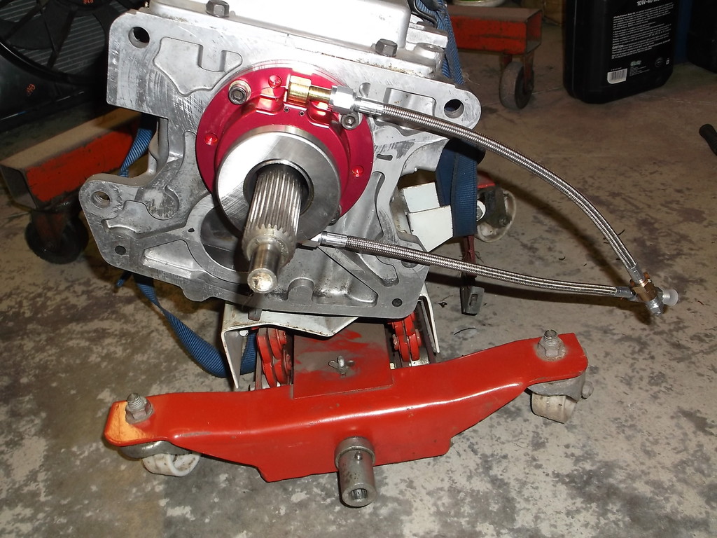
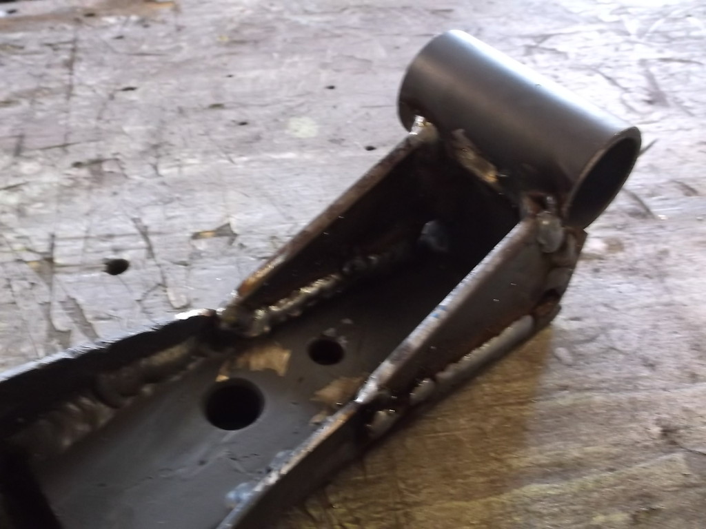
McLeod T/O bearing assembly on TKO 600. VERY important to mount with bleeder hose at top!!!
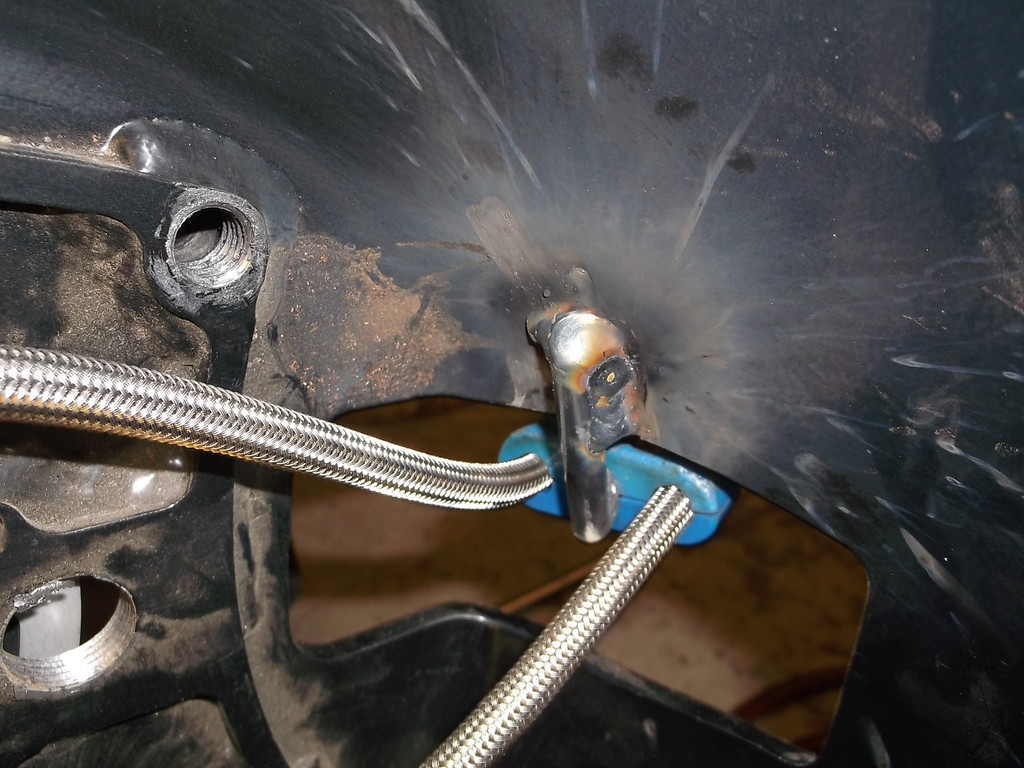
McLeod sugest to wrap braided line with heater hose to keep away from spinning clutch ang prevent them from rubbing on bellhousing or each other. This is a backyard, low buck build but even I thought that was pretty hokey. I wanted to use some type of cable clamp but wasn't sure how to mount them. I ended up using an old three hole 8mm spark plug wire clamp (remember low buck). The outer two holes gave me the proper spacing and the unused middle hole gave me a place to mount. The mounting stud is a cut and welded 5/16 bolt welded to the inside of my steel bellhousing.
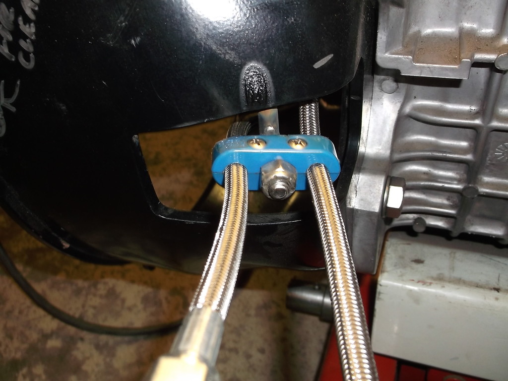
I can remove the nut and push the lines back inside the bell if I have to separate the trans from the bell.
I may later add some type of thin rubber shield to cover the clutch fork hole if water/dirt become a problem.

McLeod sugest to wrap braided line with heater hose to keep away from spinning clutch ang prevent them from rubbing on bellhousing or each other. This is a backyard, low buck build but even I thought that was pretty hokey. I wanted to use some type of cable clamp but wasn't sure how to mount them. I ended up using an old three hole 8mm spark plug wire clamp (remember low buck). The outer two holes gave me the proper spacing and the unused middle hole gave me a place to mount. The mounting stud is a cut and welded 5/16 bolt welded to the inside of my steel bellhousing.


I can remove the nut and push the lines back inside the bell if I have to separate the trans from the bell.
I may later add some type of thin rubber shield to cover the clutch fork hole if water/dirt become a problem.

Thread Starter
Senior Member
Joined: Aug 2007
Posts: 682
Likes: 45
Re: Home brew road racer
87thirdgen, thanks for following along. Once I get the engine/trans repositioned in the car I'll make up new mounts and trans crossmember and then fabricate a new trans tunnel,
I took a week off and went to ZMAX drag strip in Charlotte NC to see some old friends. They both own speed shops where they build drag race cars and sell parts.
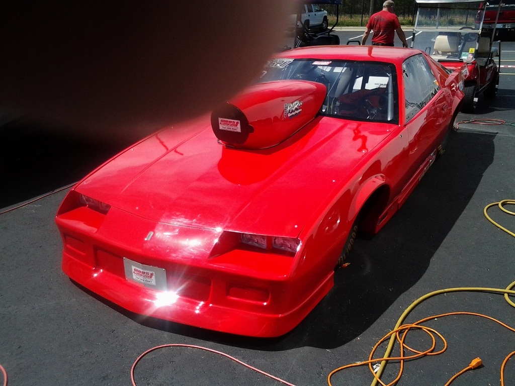
My friend Donnie deals mainly with Top Sportsman and Super Gas type cars. Here is his third gen Camaro. It runs 190's in the low 7's.
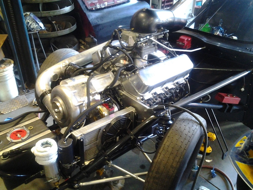
This is the engine in a T/S 63 vette that Donnie built. It has a huge F1 gear drive Procharger and direct CO2 injection to cool the intake charge. Engine makes over 2500hp. The car was fastest T/S qualifier at Charlotte with a 225mph! Donnie built the car from scratch including the chromoly frame.
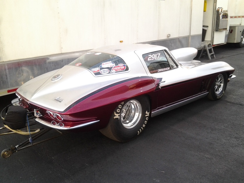
This last pic is my friend Robbie's 66 vettte that runs B modified in SS. It runs 8.50's in the 1/4 mile.Robbie builds the cars and engines himself at his shop in Fayetteville NC, Robbie likes to bang gears so the vette has a Liberty 5 speed. The engine is a a small displacement 314ci sbc running a 4.185 bore and a 2.875 stroke and spins over 10500rpm through the lights. It is a new car this year and still working the bugs out to be consistent.
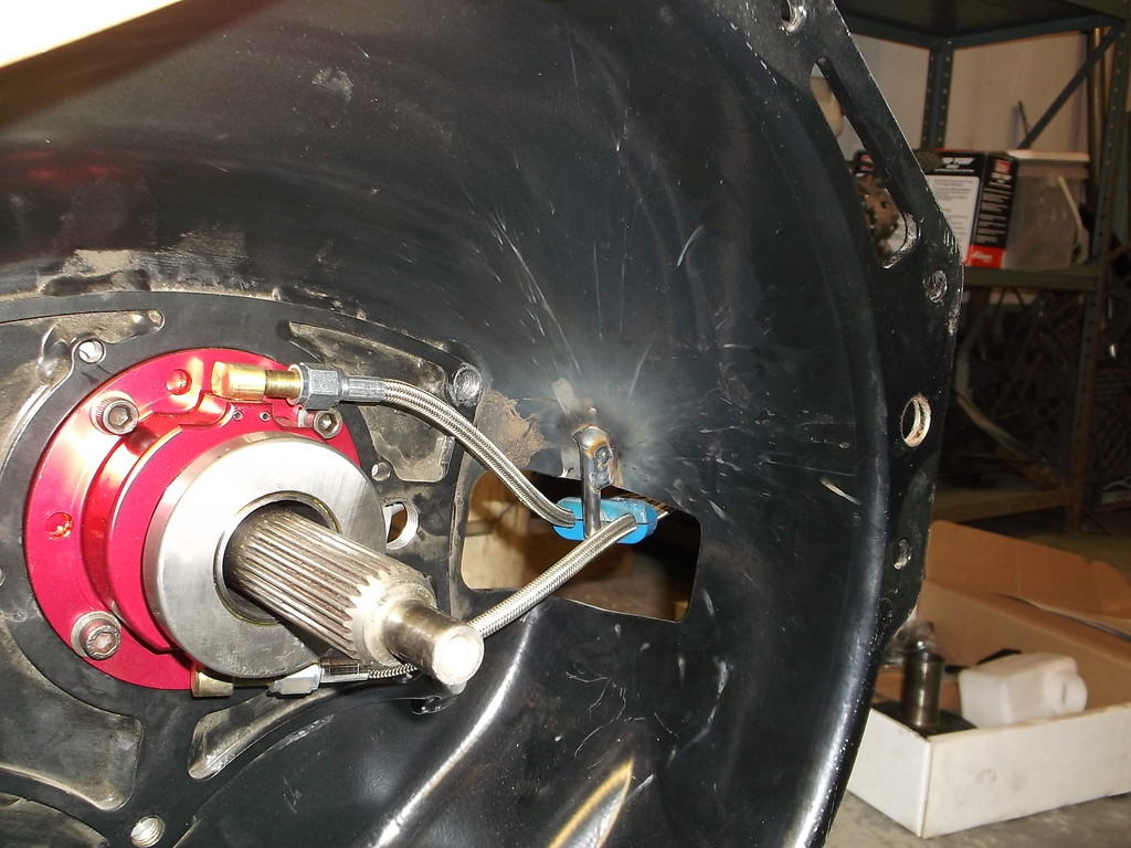
Robbie blew the rear end up a couple weeks ago in Atlanta, Can't say I ever saw one come apart like this before. Sheared all 5 studs holding the pinion retainer.
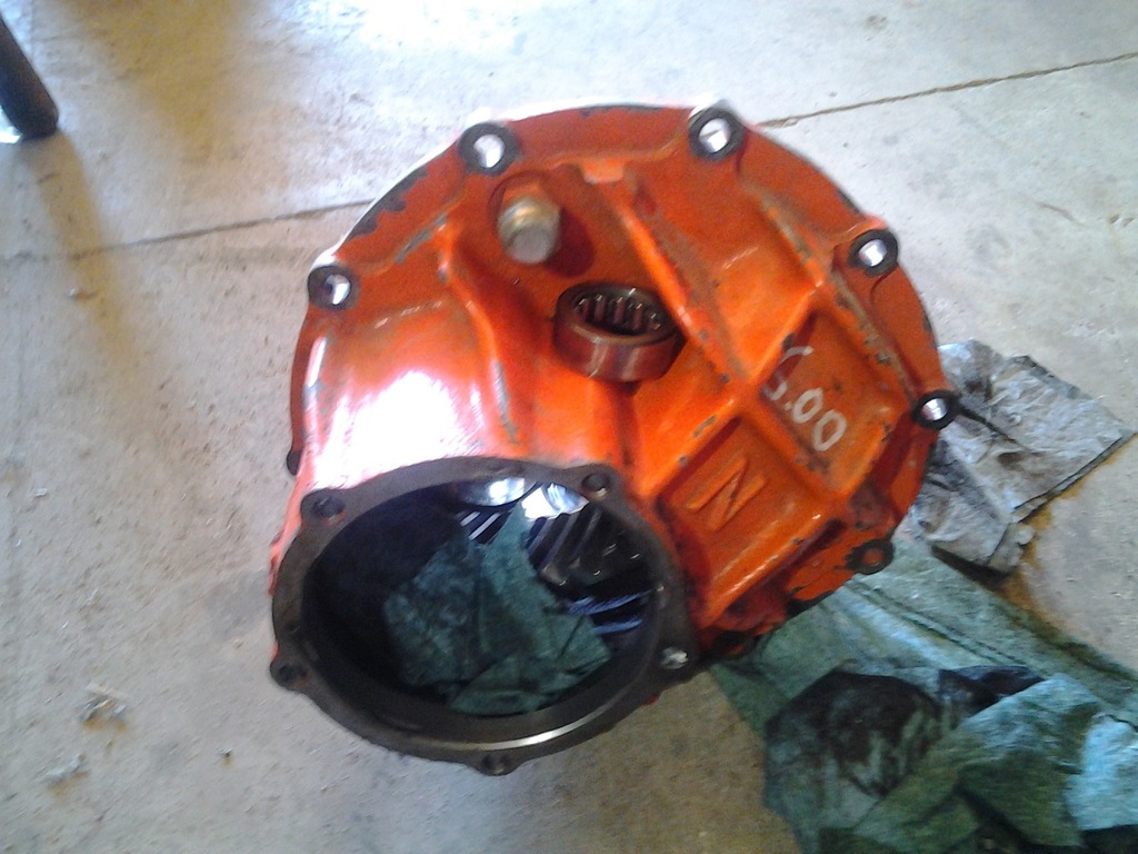
Spit the pinion out at about the 800ft mark.
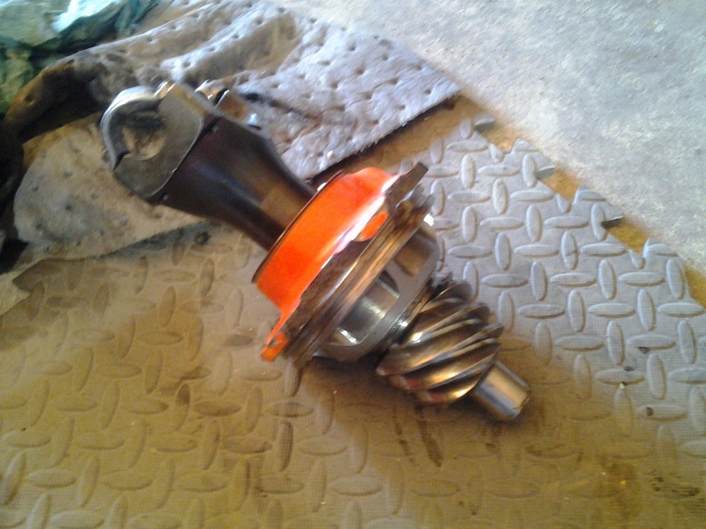
Car now has a Strange all aluminum center with a 10 bolt pinion retainer and 35 spline axles.
I took a week off and went to ZMAX drag strip in Charlotte NC to see some old friends. They both own speed shops where they build drag race cars and sell parts.
My friend Donnie deals mainly with Top Sportsman and Super Gas type cars. Here is his third gen Camaro. It runs 190's in the low 7's.

This is the engine in a T/S 63 vette that Donnie built. It has a huge F1 gear drive Procharger and direct CO2 injection to cool the intake charge. Engine makes over 2500hp. The car was fastest T/S qualifier at Charlotte with a 225mph! Donnie built the car from scratch including the chromoly frame.

This last pic is my friend Robbie's 66 vettte that runs B modified in SS. It runs 8.50's in the 1/4 mile.Robbie builds the cars and engines himself at his shop in Fayetteville NC, Robbie likes to bang gears so the vette has a Liberty 5 speed. The engine is a a small displacement 314ci sbc running a 4.185 bore and a 2.875 stroke and spins over 10500rpm through the lights. It is a new car this year and still working the bugs out to be consistent.

Robbie blew the rear end up a couple weeks ago in Atlanta, Can't say I ever saw one come apart like this before. Sheared all 5 studs holding the pinion retainer.

Spit the pinion out at about the 800ft mark.

Car now has a Strange all aluminum center with a 10 bolt pinion retainer and 35 spline axles.
Thread Starter
Senior Member
Joined: Aug 2007
Posts: 682
Likes: 45
Re: Home brew road racer
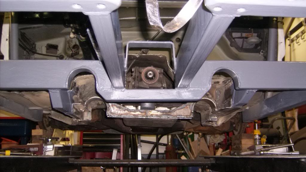
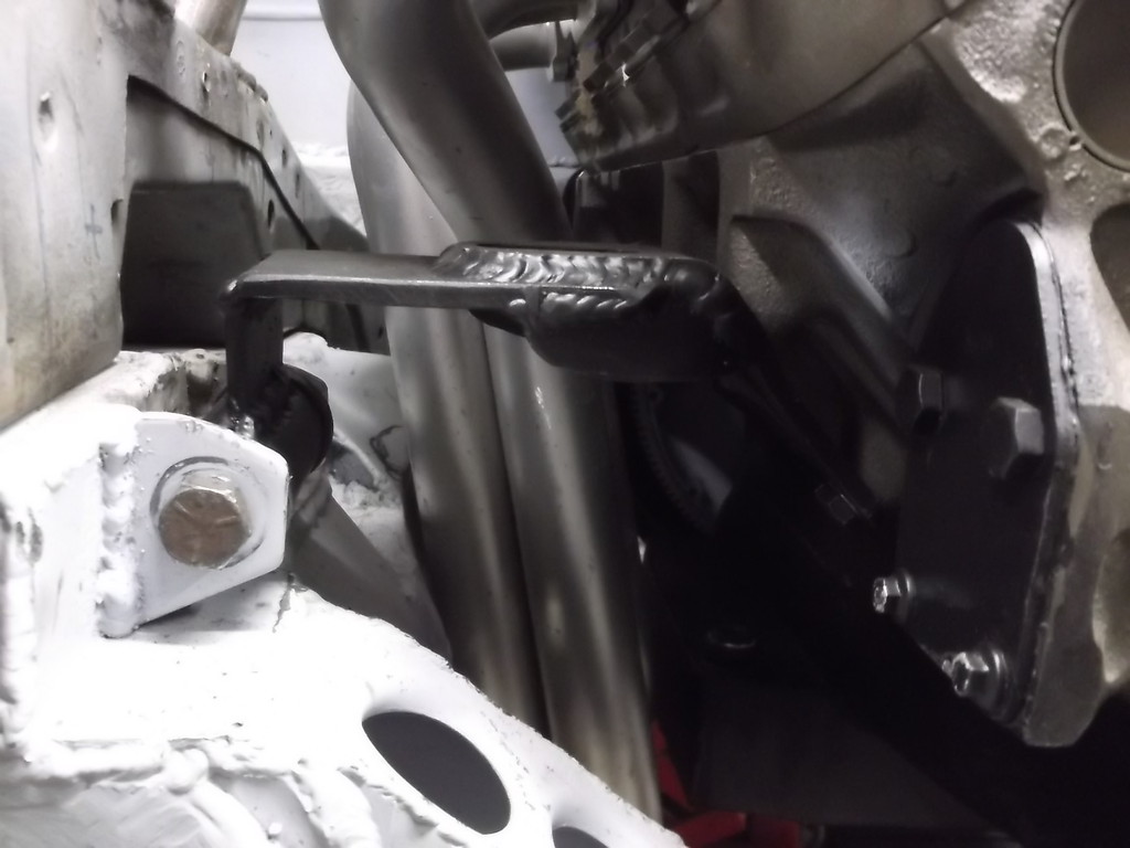
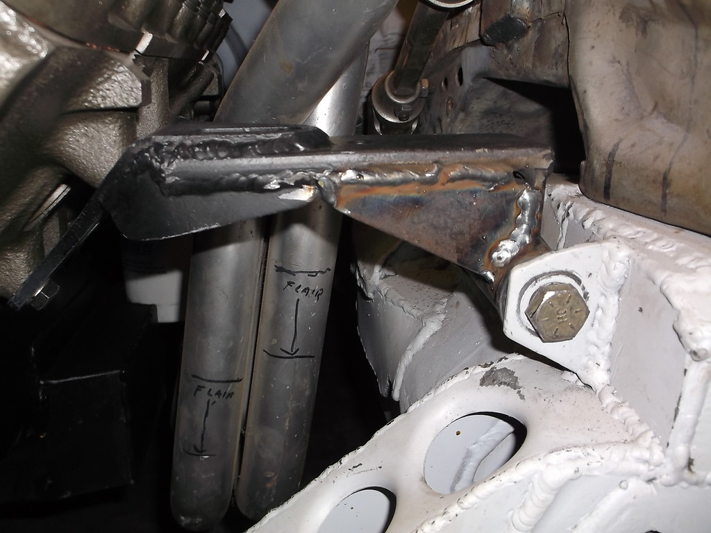
Got the engine/trans positioned back in the car and raised up for max ground clearance. I was able to raise the engine about 1 1/2" and raising the trans an inch got the drive shaft back inline with the diff. The engine angles down to rear 2 degrees and carb pad is near horizontal. I managed to get 4 1/2" at oil pan and lowest point of TKO. The bottom of the bell is 4". Big problem is still the headers as they only have 2 1/2". I will have to cut them down and try to get them at same height as the oil pan sump.
I will have to rework the engine mounts
Pan is now 1 1/2" off of k-member
Raising trans crossmember only required welding in a piece of 1x1 angle. x-member will be pulled, welded on both sides and then welds will be ground smooth. I did have to massage the floor a little to get clearance.
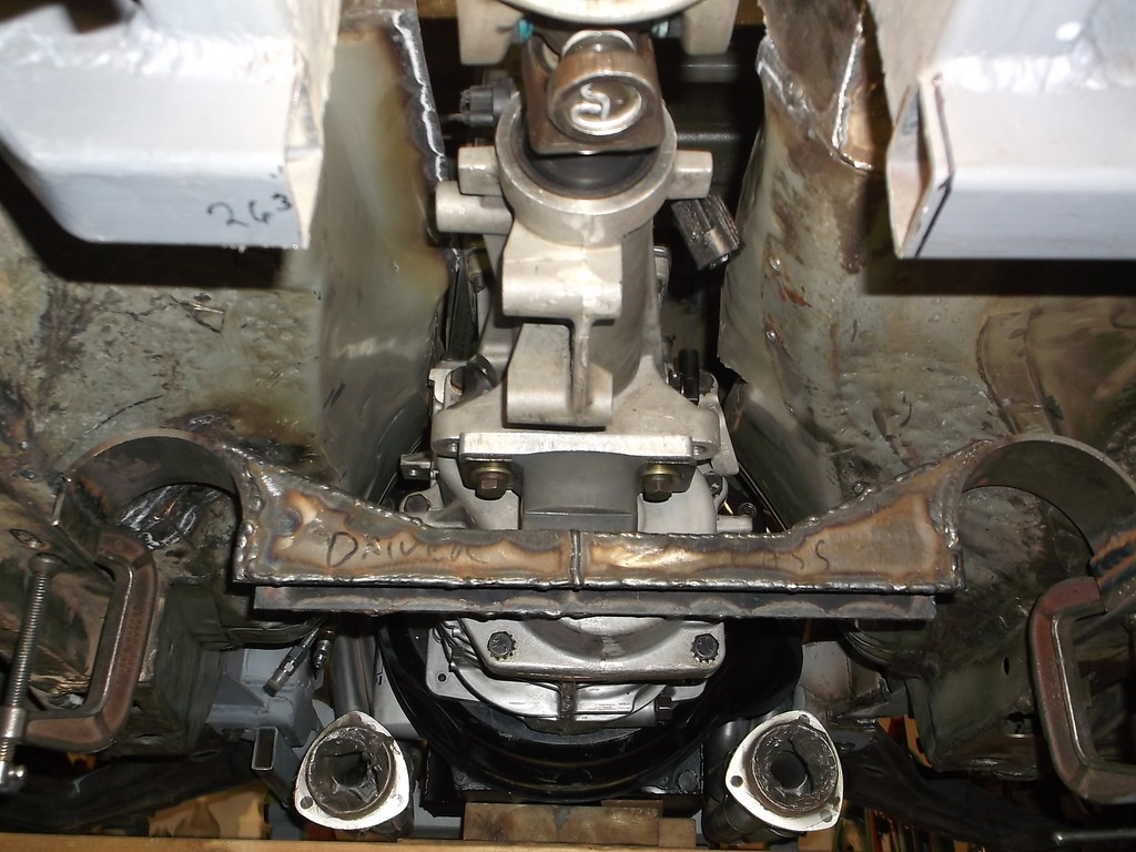
Trans is lifted to max.
Once the mounts are finished I will fab a new tunnel from 20ga.
I will have to rework the engine mounts


Pan is now 1 1/2" off of k-member

Raising trans crossmember only required welding in a piece of 1x1 angle. x-member will be pulled, welded on both sides and then welds will be ground smooth. I did have to massage the floor a little to get clearance.


Trans is lifted to max.


Once the mounts are finished I will fab a new tunnel from 20ga.
Thread Starter
Senior Member
Joined: Aug 2007
Posts: 682
Likes: 45
Re: Home brew road racer
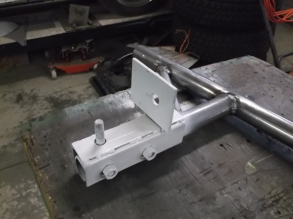
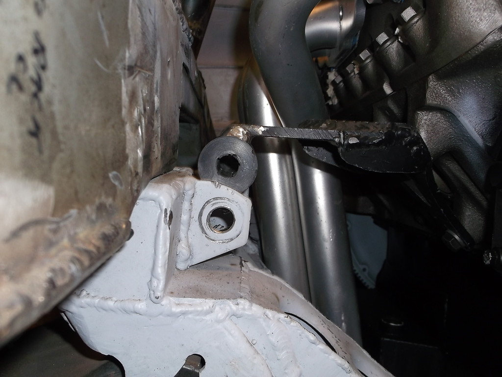
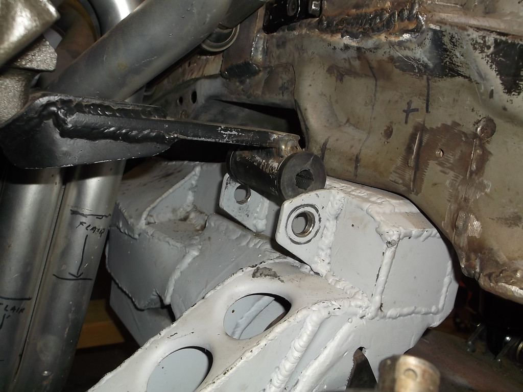
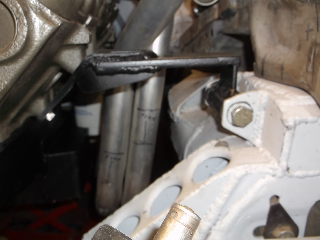
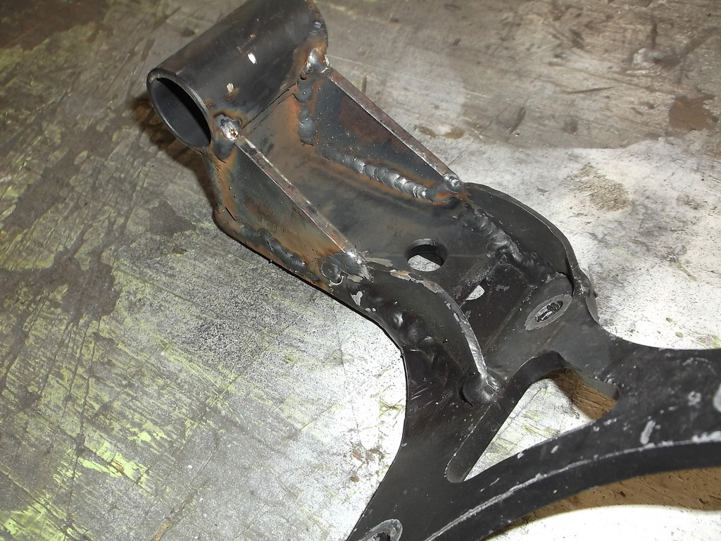
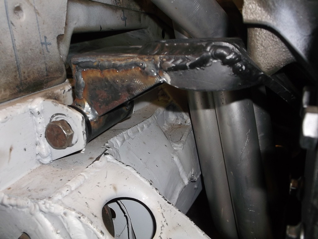
Engine mounts are done for now. Thinking I might want to tie the extended vertical leg into the horizontal arm similar to what I did on the engine side of mount.
Cleaned up the trans x-member and reinstalled.
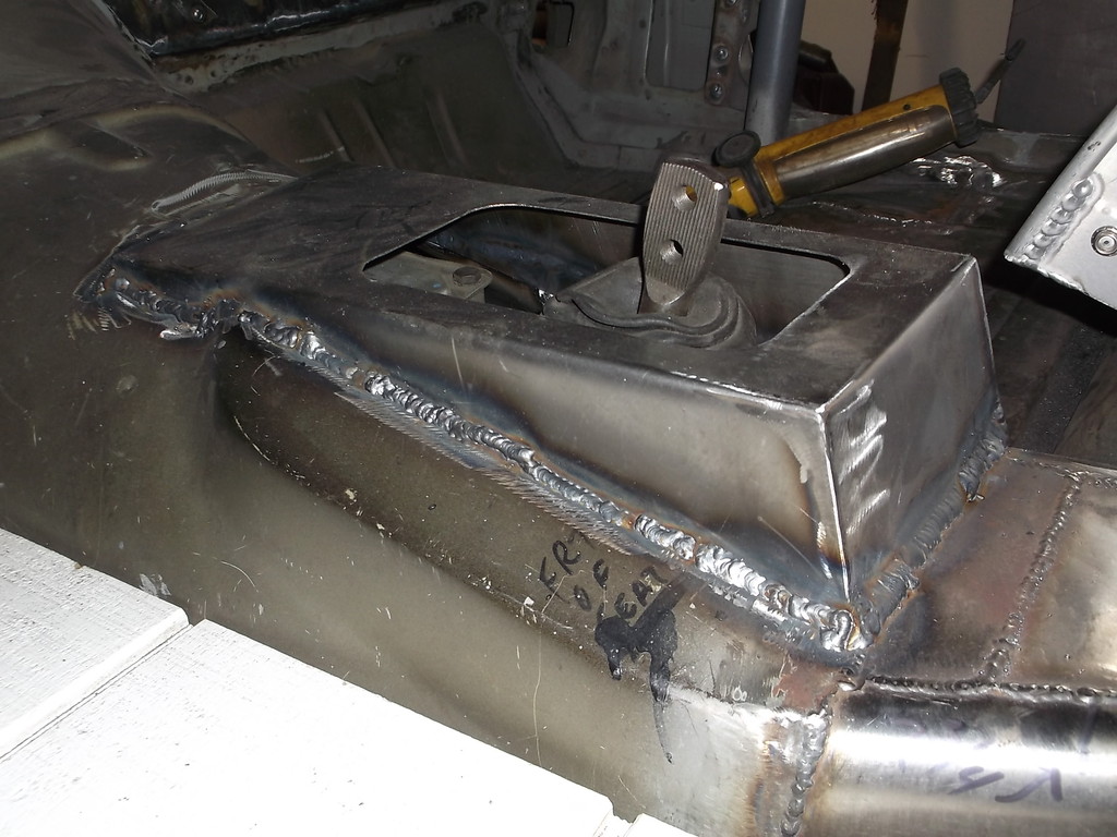
With drivetrain back in place I started work on new tunnel. I will open hole around shifter large enough to remove entire shifter housing from trans. Removing that gains about 4" of clearance if removing trans from car.


Cleaned up the trans x-member and reinstalled.


With drivetrain back in place I started work on new tunnel. I will open hole around shifter large enough to remove entire shifter housing from trans. Removing that gains about 4" of clearance if removing trans from car.


Joined: Dec 2005
Posts: 6,499
Likes: 31
From: Macon, GA
Car: 1992 Camaro RS
Engine: Vortec headed 355, xe262
Transmission: T56
Axle/Gears: 9-bolt 3.70
Re: Home brew road racer
Ive seen some pretty stout engine mounts bend... especially with power and manual transmissions. You might want to beef those up a bit.
Member
Joined: May 2001
Posts: 438
Likes: 1
From: state of confusion
Car: '08 Mustang GT
Engine: 4.6L
Transmission: � � 0 . . . |-|-|
Axle/Gears: 8.8", 3.55
Re: Home brew road racer
I'm inclined to agree ↑↑↑. They look just a bit on the 'flexible' side even if they're plenty strong for normal street driving in traffic.
Norm
Norm

Member
Joined: Jan 2010
Posts: 247
Likes: 8
Re: Home brew road racer
Thread Starter
Senior Member
Joined: Aug 2007
Posts: 682
Likes: 45
Re: Home brew road racer
For the motor mounts I will probably reinforce the frame side like I did the engine side with 1/8" sheet steel on the front and back sides. This will effectively make the mount a 3 sided box with just the bottom open. I'll take care of them after I finish the tunnel mods.
A message to Propaintball:
What type of trans fluid did you use in the TKO? Every seal in it is swollen and mushy like what happens when you have oil in a brake system. I was able to get replacements for the tailshaft seal and shifter dust boot but just discovered there is an oil seal on the bottom of the shift plate.


Member
Joined: Jan 2010
Posts: 247
Likes: 8
Re: Home brew road racer
I think you should put a gusset plate between the vertical plate where the cylinder is welded to and the horizontal flat plate.
Also, it was so long ago I don't remember the exact fluid I used but I know for sure that it was what tremec called for in their manual. Im sure you could find that out online?
Thread Starter
Senior Member
Joined: Aug 2007
Posts: 682
Likes: 45
Re: Home brew road racer
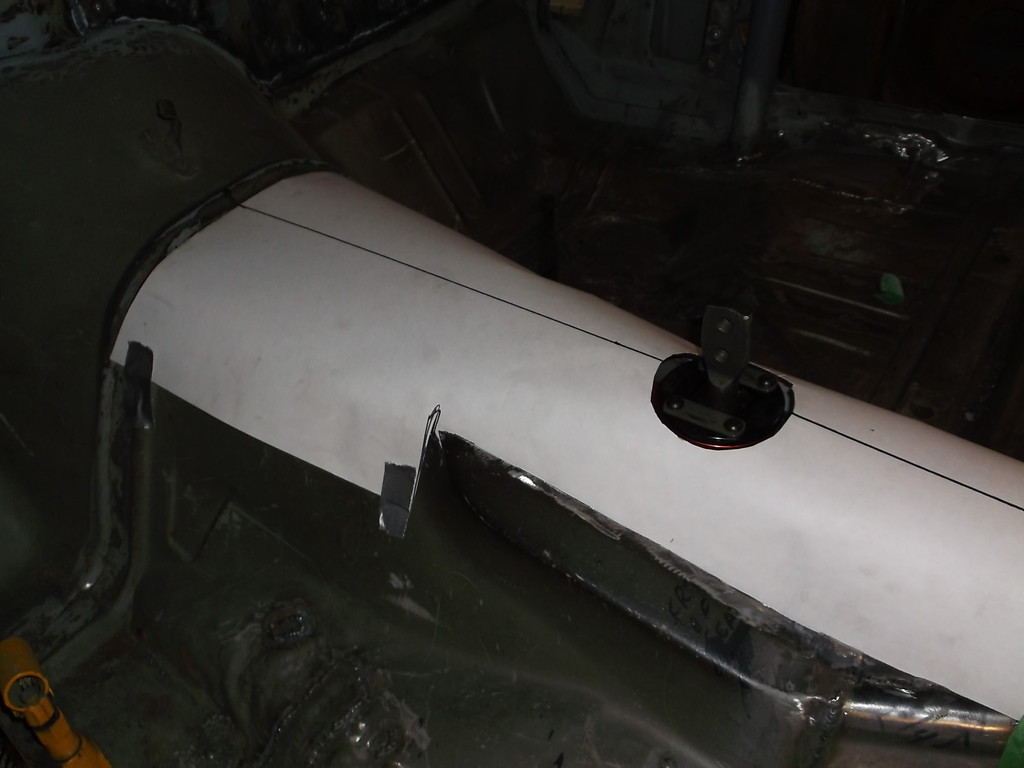
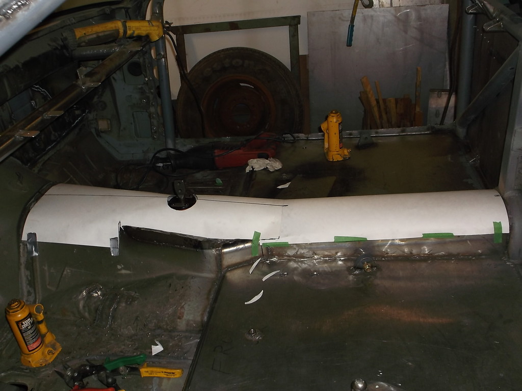
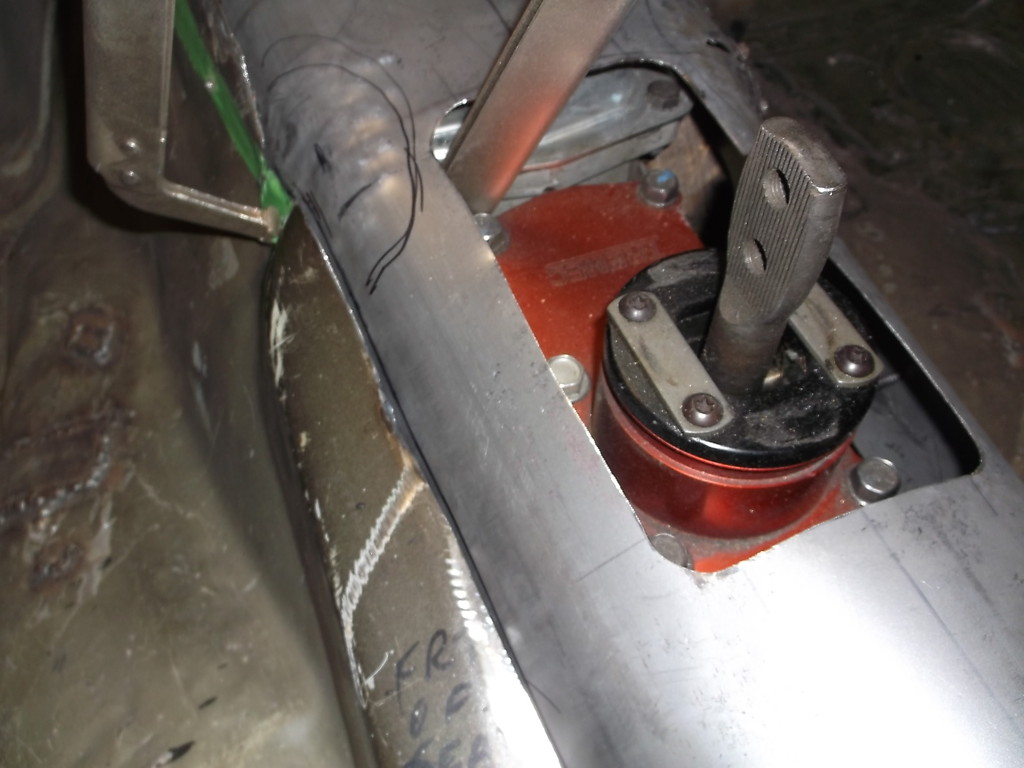
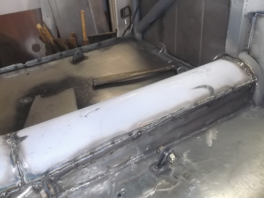
I got the new tunnel ruffed in. Will need to trim and weld in. Also need to replace top half of front driveshaft loop.
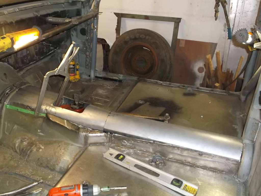
trying to keep the tunnel over trans low so had to dimple out the sides to clear access covers.
Tunnel over driveshaft was raised about 3" at rear and 4" in front.

trying to keep the tunnel over trans low so had to dimple out the sides to clear access covers.


Tunnel over driveshaft was raised about 3" at rear and 4" in front.

Thread Starter
Senior Member
Joined: Aug 2007
Posts: 682
Likes: 45
Re: Home brew road racer
Haven't had time to work on the Z these past few weeks. Weather turned nice and had too many outdoor projects to take care of. Its supposed to rain most of the weekend so maybe I'll get the tunnel welded back in.
Thread Starter
Senior Member
Joined: Aug 2007
Posts: 682
Likes: 45
Re: Home brew road racer
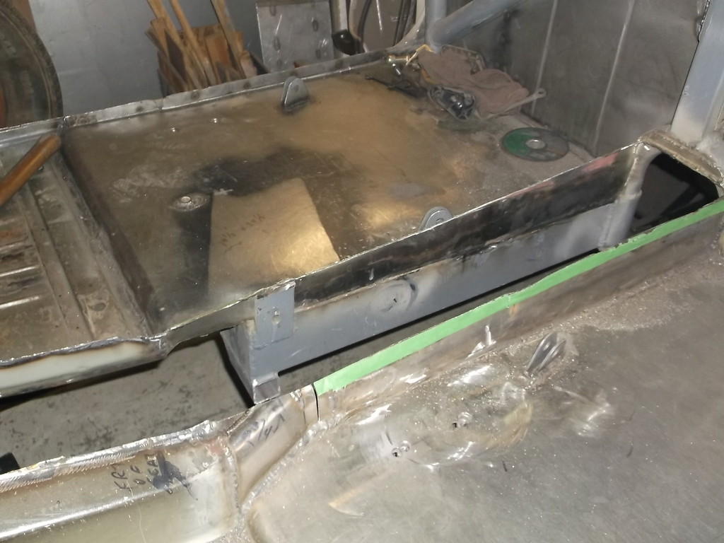
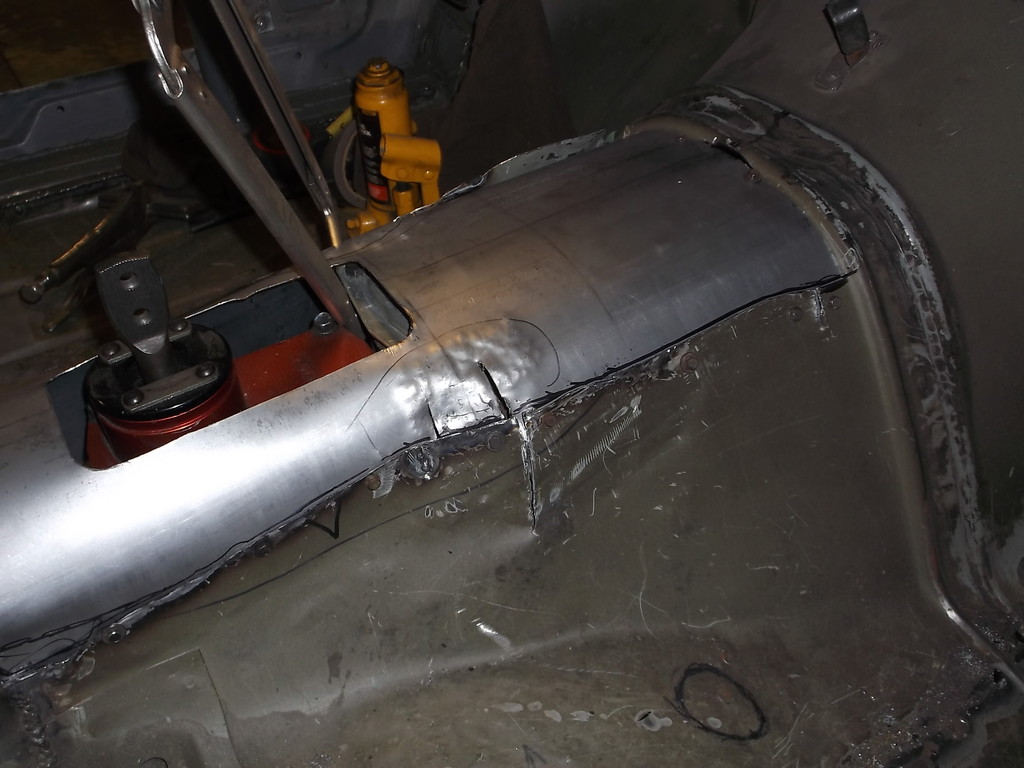
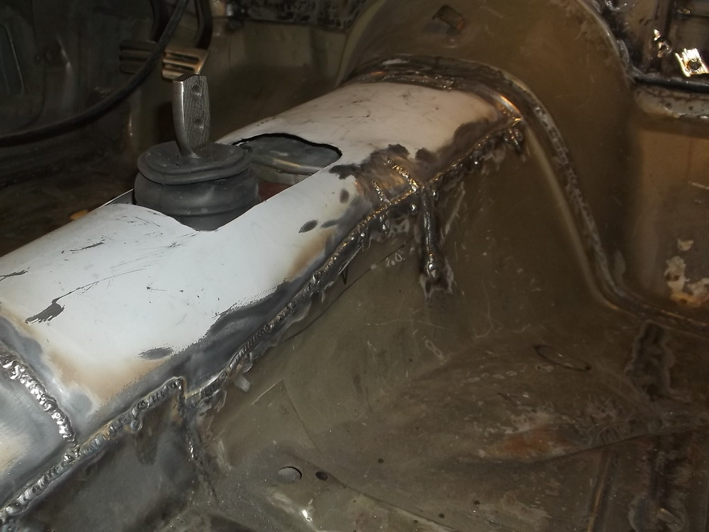
Ok tunnel is finally back in.
Here is what I had made originally. Just a box to clear the top, rear of trans.
And this is what it looks like now that the engine and trans had to be raised for ground clearance.
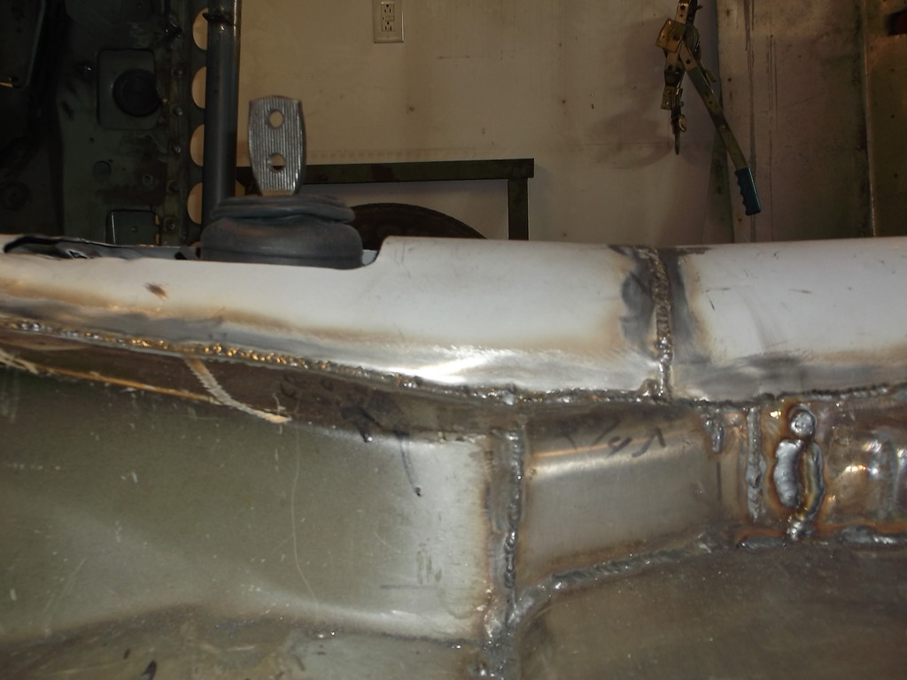
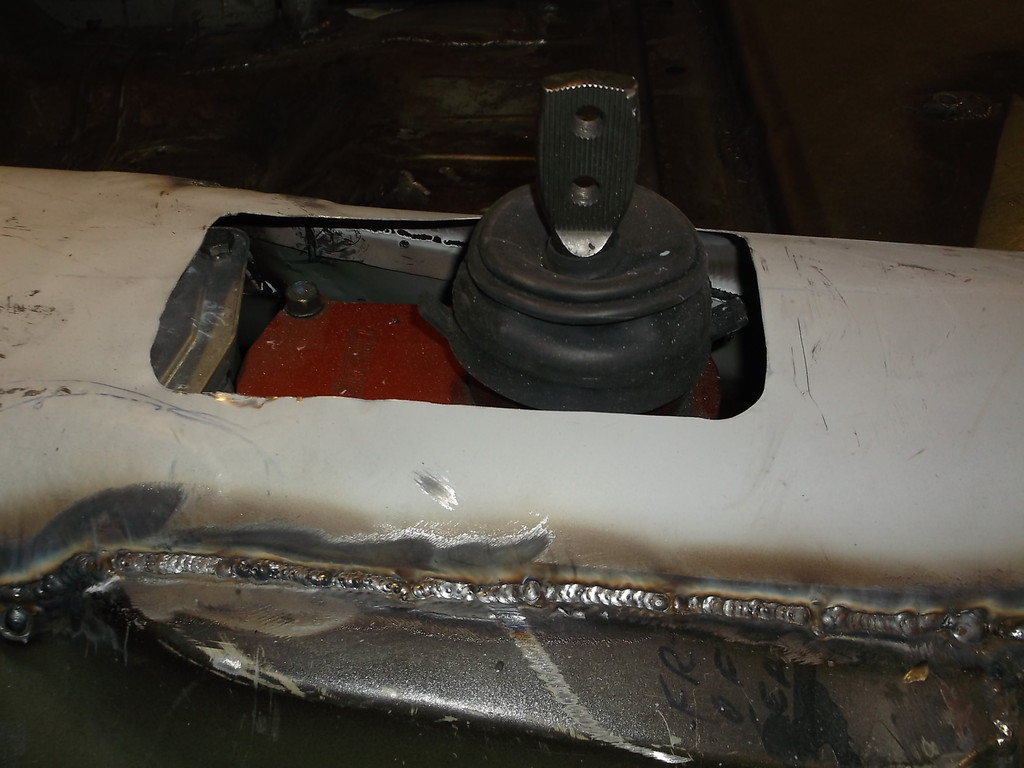
You can see here that I had to raise the front of the tunnel to where the firewall and floor pan seams overlap. Clearance around top of trans is minimal, 3/8" to 1/2" is all.
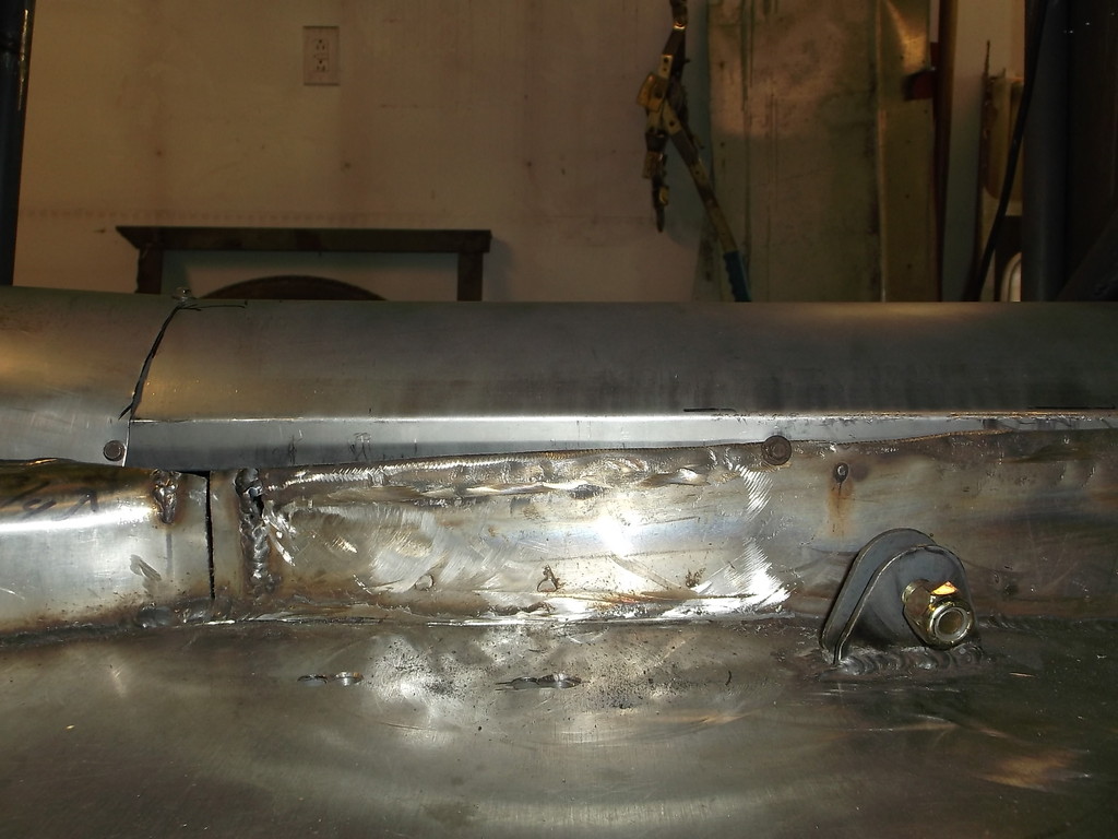
welded in a new upper half of driveshaft loop.
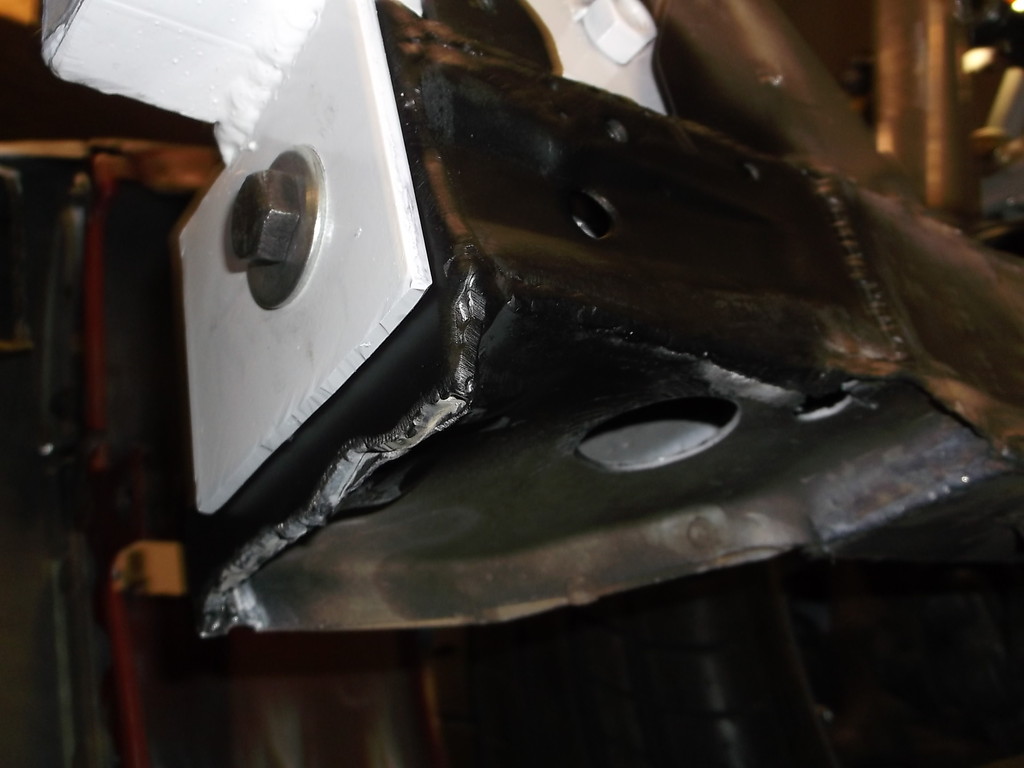
Also beefed up the engine mounts with 1/4" plate. I feel a lot better about these now.
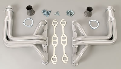
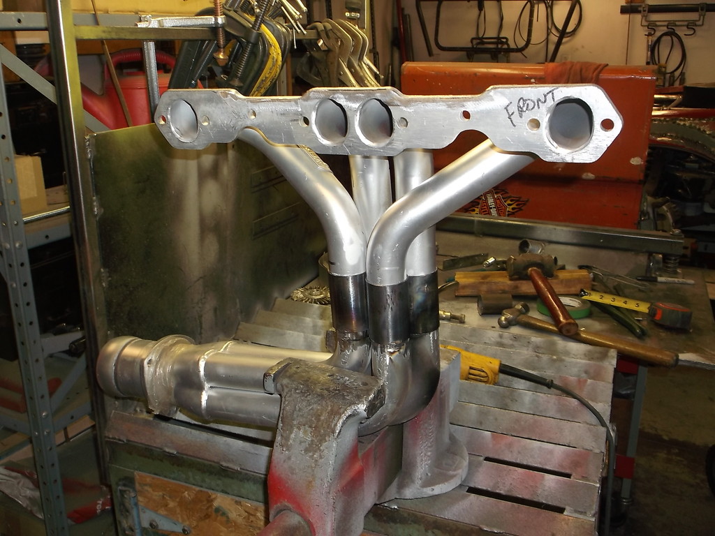
The last major modification I need to do before I can think about plumbing and wiring is to shorten the headers 1 1/2" to 2" and rotate the exits to the outside a little bit. I plan on cutting through the headers where they come together as a group of 4 tubes but in a stepped pattern, shorten the bottom tubes by 2", weld 2" long sleeves over the bottom tubes and slide the top tubes back down inside. This should allow me to adjust the length up and down, and also allow me to twist or rotate the bottom half to the outside a little to better align the collectors and extension pipes running along side the trans.
Here are the headers I have. Hedman Elite series for a C3 vette. You can see how the 4 primary pipes form a tight bundle once they turn vertical. This is where I will cut and splice.
Here is what I had made originally. Just a box to clear the top, rear of trans.

And this is what it looks like now that the engine and trans had to be raised for ground clearance.


You can see here that I had to raise the front of the tunnel to where the firewall and floor pan seams overlap. Clearance around top of trans is minimal, 3/8" to 1/2" is all.

welded in a new upper half of driveshaft loop.

Also beefed up the engine mounts with 1/4" plate. I feel a lot better about these now.


The last major modification I need to do before I can think about plumbing and wiring is to shorten the headers 1 1/2" to 2" and rotate the exits to the outside a little bit. I plan on cutting through the headers where they come together as a group of 4 tubes but in a stepped pattern, shorten the bottom tubes by 2", weld 2" long sleeves over the bottom tubes and slide the top tubes back down inside. This should allow me to adjust the length up and down, and also allow me to twist or rotate the bottom half to the outside a little to better align the collectors and extension pipes running along side the trans.
Here are the headers I have. Hedman Elite series for a C3 vette. You can see how the 4 primary pipes form a tight bundle once they turn vertical. This is where I will cut and splice.

Thread Starter
Senior Member
Joined: Aug 2007
Posts: 682
Likes: 45
Re: Home brew road racer
I got the headers shortened up and the drivers side exhaust mostly fitted.
I needed to shorten the headers almost 2". I marked the cut with 2" duct tape.
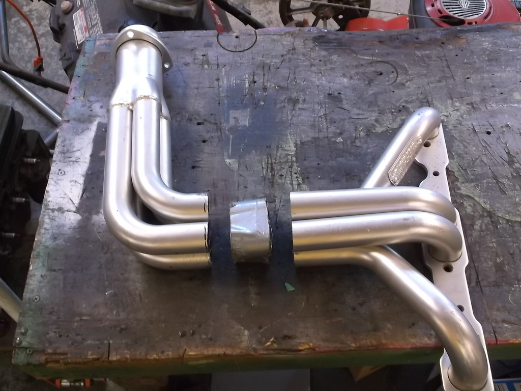
Next I cut four, 2 3/8" long pieces of 1 3/4od, .060 wall and tacked to bottom half of headers
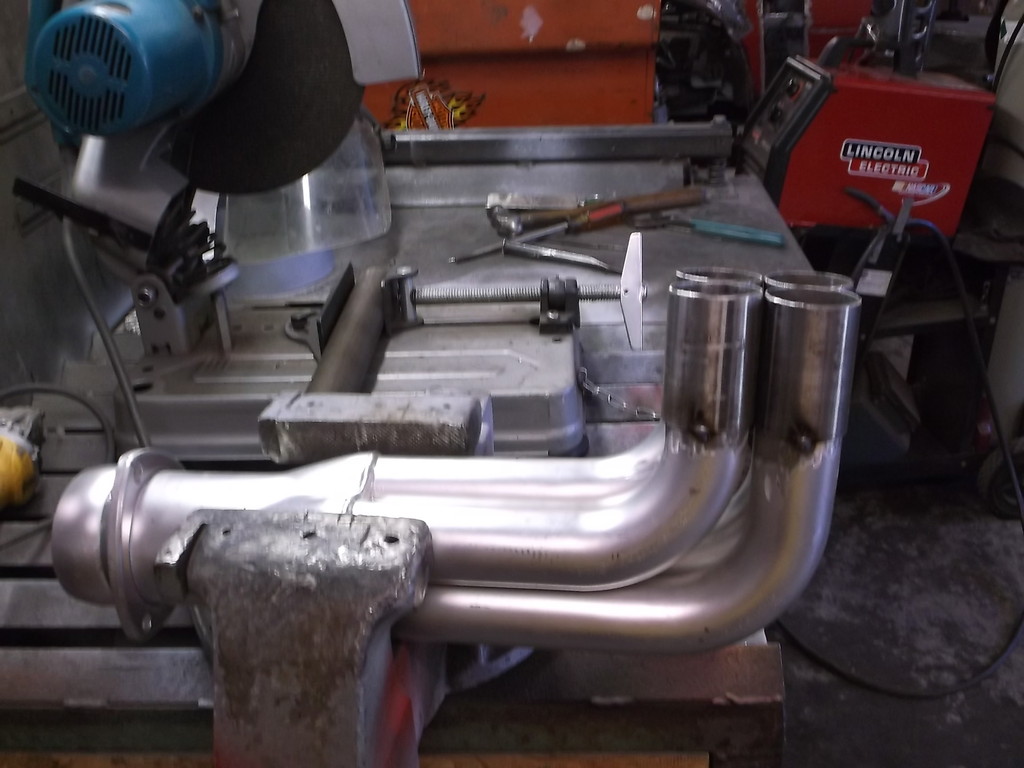
After some effort to get all four pipes back in the 1 3/4 tubes I persuaded the top half back into the bottom half nearly the full 2".
I put the headers back on the car and was able to twist the collectors outward to better align with the extension pipes running along side the transmission.
Header now lines up with trans x-member and frame cutout.
Once I had the headers in the correct orientation I tack welded a couple tubes and the removed to finish welding. Just for the curious, the total height from top of header flange to bottom of collector is now just 16".
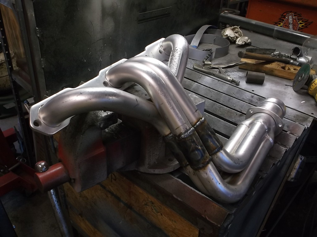
I have to say I am very happy with how they fit now. They actually sit a little higher up than the 7" deep oil pan.
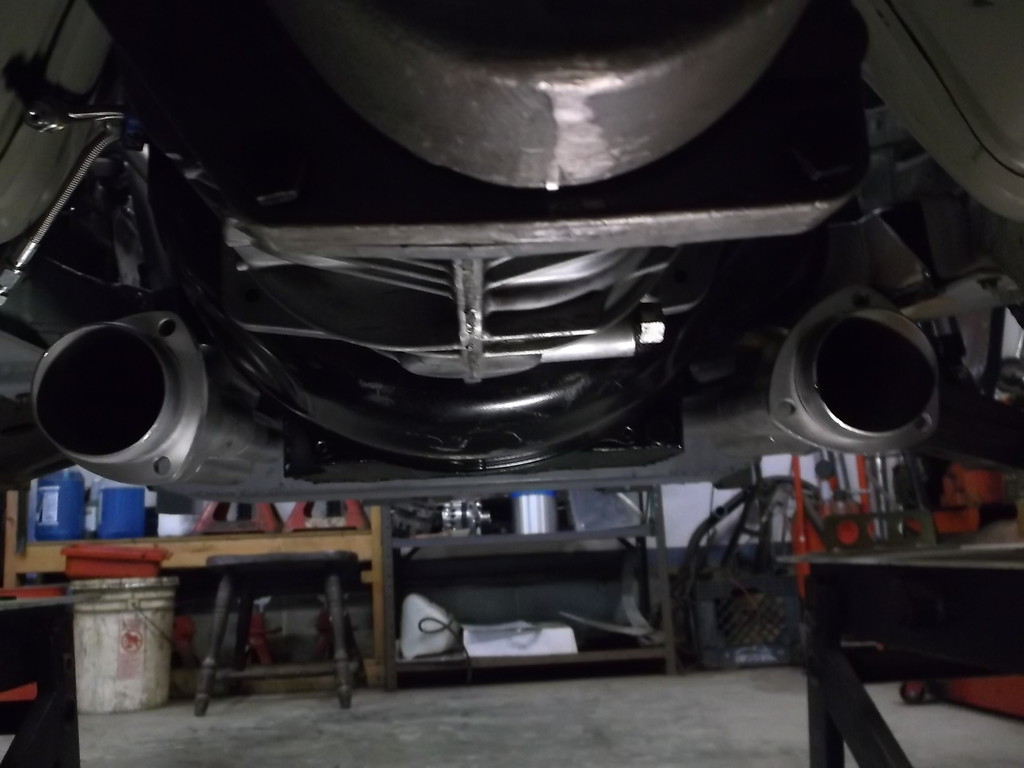
And are higher than the oe sub frame.
I needed to shorten the headers almost 2". I marked the cut with 2" duct tape.

Next I cut four, 2 3/8" long pieces of 1 3/4od, .060 wall and tacked to bottom half of headers

After some effort to get all four pipes back in the 1 3/4 tubes I persuaded the top half back into the bottom half nearly the full 2".

I put the headers back on the car and was able to twist the collectors outward to better align with the extension pipes running along side the transmission.
Header now lines up with trans x-member and frame cutout.

Once I had the headers in the correct orientation I tack welded a couple tubes and the removed to finish welding. Just for the curious, the total height from top of header flange to bottom of collector is now just 16".


I have to say I am very happy with how they fit now. They actually sit a little higher up than the 7" deep oil pan.

And are higher than the oe sub frame.

Thread Starter
Senior Member
Joined: Aug 2007
Posts: 682
Likes: 45
Re: Home brew road racer
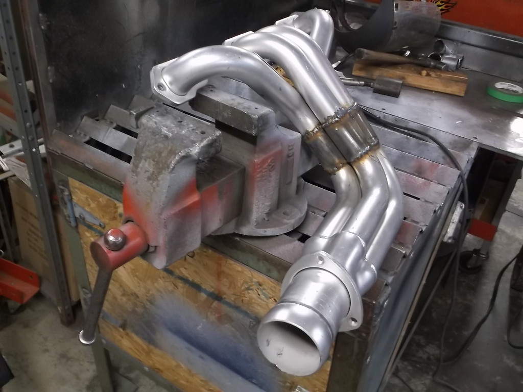
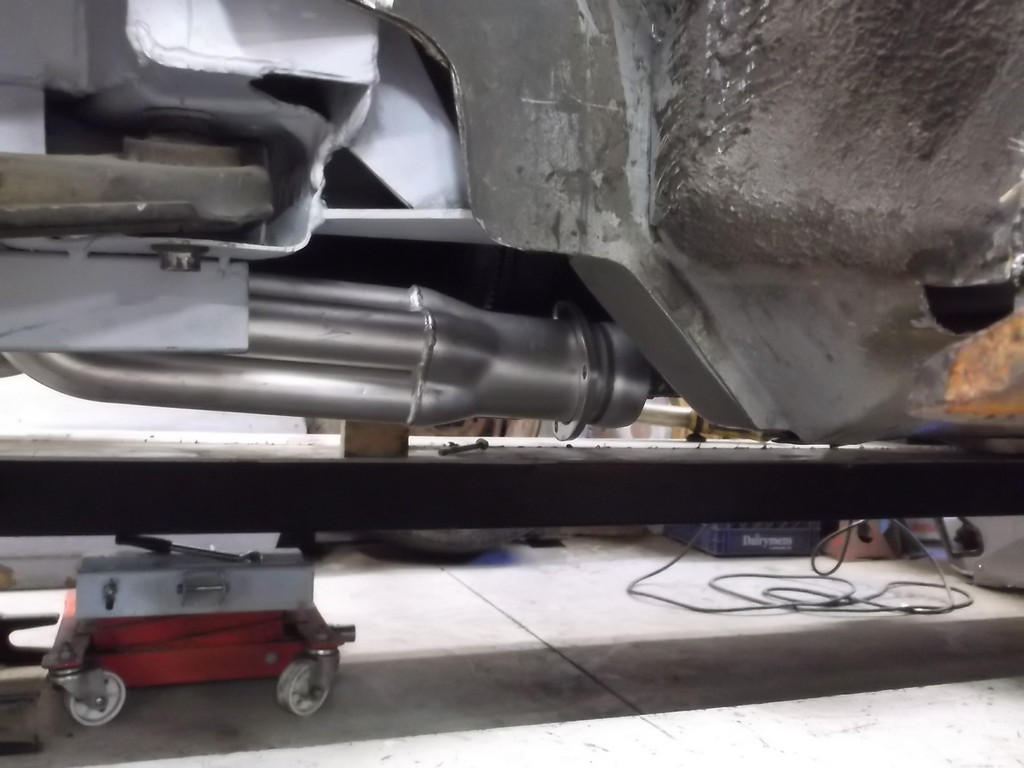
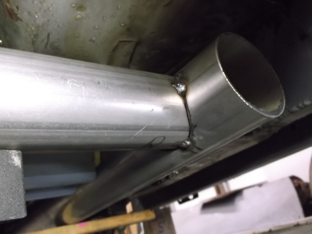
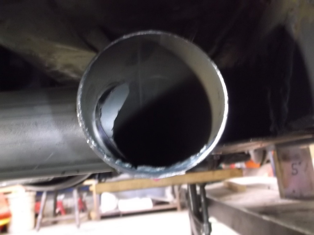
With the header collectors in the correct location now, I turned to fitting the exhaust up. I had originally planed on a true dual 2.5" system with an H-pipe. With the engine at 455hp and capable of 500+ with a cam change I thought I would step it up a bit. I decided to run 3" collector extensions all the way to the H-pipe at the back of the trans. This makes the extensions 24" long. I am incorporating the H-pipe into the extensions and using 2.5" tubing for the connector pipe. Even going to the 3" extnsions they still sit above the bottom of the OE subframe.
You can see in the picture above the 3" to 2.5" pipe adapter just after the H-pipe. This allows me to connect to the 2.5" Magnaflow mufflers and side exit tailpipes that fit under the floor pan below the seats,

All of the exhaust from the headers back is even with or higher than the SFC's and the OE front subframe. This was a goal of mine from the onset of this project; long tube headers, true duals, side exit exhaust, AND ground clearance. The ground clearance at the sfc's is 5" and the suspension has about 2.5" of compression travel. The exhaust, engine and drive train all had to be designed and built to work within these parameters.
With most of the mechanical mods done (plumbing and wiring are next) I think I have achieved nearly all of the modification goals on the car. Due to the lack of talent, tools and/or money I have had to scale back on some of my ideas but with the exception of building the 383 engine instead of the 355, there has been no mission creep or changing coarse in mid stream. This is the car I wanted to build and hopefully it will perform to my expectations.

You can see in the picture above the 3" to 2.5" pipe adapter just after the H-pipe. This allows me to connect to the 2.5" Magnaflow mufflers and side exit tailpipes that fit under the floor pan below the seats,


All of the exhaust from the headers back is even with or higher than the SFC's and the OE front subframe. This was a goal of mine from the onset of this project; long tube headers, true duals, side exit exhaust, AND ground clearance. The ground clearance at the sfc's is 5" and the suspension has about 2.5" of compression travel. The exhaust, engine and drive train all had to be designed and built to work within these parameters.
With most of the mechanical mods done (plumbing and wiring are next) I think I have achieved nearly all of the modification goals on the car. Due to the lack of talent, tools and/or money I have had to scale back on some of my ideas but with the exception of building the 383 engine instead of the 355, there has been no mission creep or changing coarse in mid stream. This is the car I wanted to build and hopefully it will perform to my expectations.


Thread Starter
Senior Member
Joined: Aug 2007
Posts: 682
Likes: 45
Re: Home brew road racer
Scooter, I was able to weld more than 80% around each tube, with a few close to 90%.
I am not worried about them leaking as the tubes inserted in from the top set down inside the outer tubes nearly 1 3/4" and the tubes fit together very tight. I will just have to see if they leak or not once it is running. The primary tubes are a little small for this engine at 1 5/8 od. If the car drives as well as I hope it does then it might be worth the effort to make a similar set with 1 3/4 primary tubes.
I am not worried about them leaking as the tubes inserted in from the top set down inside the outer tubes nearly 1 3/4" and the tubes fit together very tight. I will just have to see if they leak or not once it is running. The primary tubes are a little small for this engine at 1 5/8 od. If the car drives as well as I hope it does then it might be worth the effort to make a similar set with 1 3/4 primary tubes.

Joined: Sep 1999
Posts: 4,353
Likes: 308
From: NJ
Car: 92 Firebird
Engine: 4.8 LR4
Transmission: T56
Axle/Gears: 3.45 9 Bolt
Re: Home brew road racer
It's definitely going to leak if you don't get that weld 100% around. At least with the collector joint they can weld from the inside so they don't leak. They usually weld the tubes together and put in a star to close up the middle, then they just have to meet the weld on the outside to the "corner" of the tube
Thread Starter
Senior Member
Joined: Aug 2007
Posts: 682
Likes: 45
Re: Home brew road racer
Scooter, I'll just have to wait and see. I chose this route after looking at various header designs form Hooker, Hedman,etc. They all use a slip fit on many of there competition long tube setups where one or more tubes have to go around a frame rail. Also same applies to slip on collectors. I understand that the competition headers are normally found on race only cars where they're not overly concerned with small exhaust leak noise or possible exhaust fumes but it is a widely used header design feature so it can't be too bad.
Remember that the tubes are not butt welded together. The outer sleeves overlap the bottom tubes by 3/8 to 1/2" and the top tubes by 1 1/2 to 1 3/4". I might also benefit from thermal expansion. I don't think the sleeves will get as hot as the header tubes as they won't see direct exhaust flame so the header tube may expand into the sleeve for an even tighter fit. We'll just have to wait and see. If they do leak badly I think I might be able to get a small torch tip close enough to either gas weld or braze the inside seams.
Remember that the tubes are not butt welded together. The outer sleeves overlap the bottom tubes by 3/8 to 1/2" and the top tubes by 1 1/2 to 1 3/4". I might also benefit from thermal expansion. I don't think the sleeves will get as hot as the header tubes as they won't see direct exhaust flame so the header tube may expand into the sleeve for an even tighter fit. We'll just have to wait and see. If they do leak badly I think I might be able to get a small torch tip close enough to either gas weld or braze the inside seams.
Member
Joined: May 2001
Posts: 438
Likes: 1
From: state of confusion
Car: '08 Mustang GT
Engine: 4.6L
Transmission: � � 0 . . . |-|-|
Axle/Gears: 8.8", 3.55
Re: Home brew road racer
Years ago, I used very much the same sort of slip-fit connection when crossing the Malibu's driver side exhaust over to Y-connect with the passenger side exhaust line, this being downstream of the header flanges. The reason was to Y the two lines into a 4" inlet / 4" outlet catalytic converter and split them back on the outlet side, and the slip-fit was done to reduce thermal stresses and eliminate header gasket problems. It was a full slip-fit intended to slide in service, no welding together of the two exhaust pipes at all.
I never noticed any fumes or noise even though it wasn't 100% tight against the kind of backpressure you could generate by covering both exhaust pipes with rags held in gloved hands.
What I did notice was that the outer sleeve's end tended to oval out a little bigger with time, but I think your situation will be much less likely to do that as long as you allow the rest of the exhaust lines to freely expand rearward. Don't hard-mount it anywhere in any direction, as piping expansion quickly becomes a 3-D problem when over-restrained pipe kind of "pops" out of plane when that's the path of least resistance.
I'm afraid that I did that job before I had a digital camera and that I may not have taken any pictures at all. I'm a little slow updating my sig, as the Malibu was sold about 4 years ago.
Norm
Last edited by Norm Peterson; Jun 19, 2016 at 11:23 AM.
Thread Starter
Senior Member
Joined: Aug 2007
Posts: 682
Likes: 45
Re: Home brew road racer
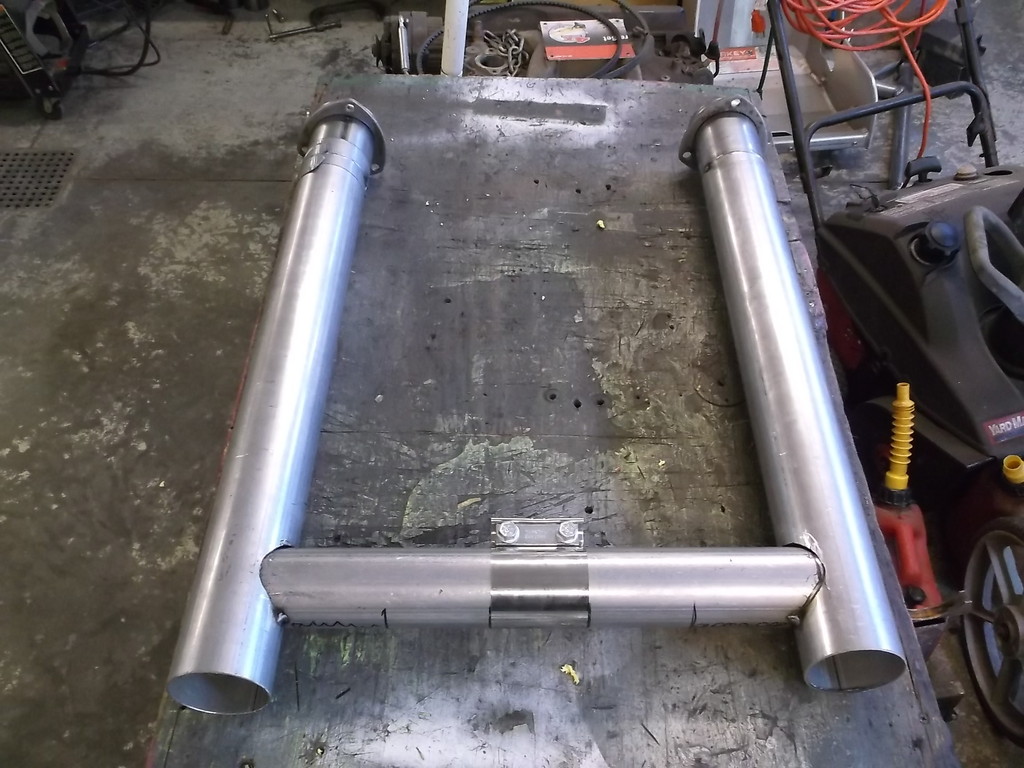
more work on the H-pipe. I got the open end of both collector extension tubes set at the same height, slipped the balance tube into the left side pipe and used a level to get it parallel to the ground. I marked its position on the right side tube and cut out a 2 3/8" hole there. I used a rotary file to finish the hole size trying hard to keep a snug fit. With the tube inserted into both pipes I was able to reach in from the end and mark the tubing where it protruded into the extension tubes. I then removed the balance tube and trimmed the excess material, leaving about 1/8" to protrude into the extension pipes.
Right side extension pipe
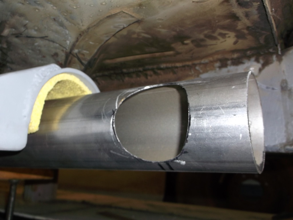
balance tube trimmed up. Inner marker lines show where outer wall of extension pipe will be.
Balance tube leveled and tacked in place.
And a look from inside the extension pipe.
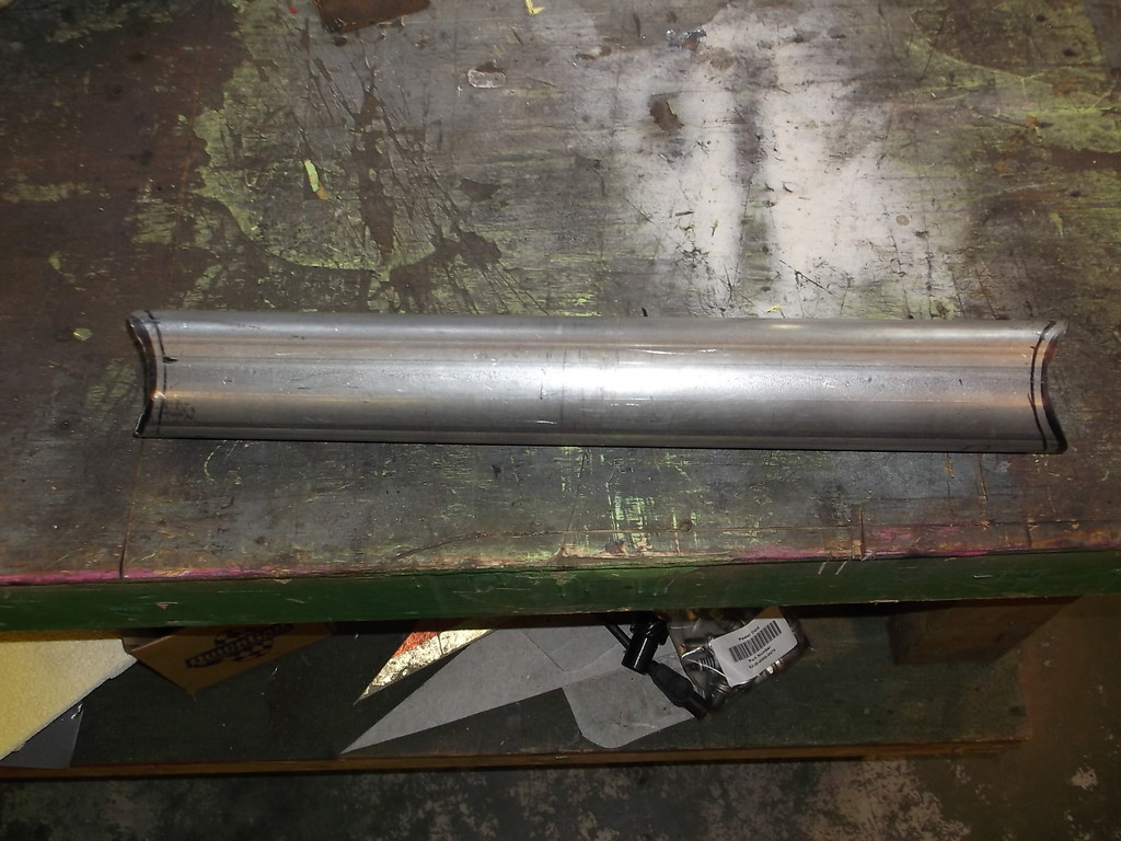
I decided to cut the balance tube in half and use a band clamp to hold it together. This allows me to adjust the width at the back of the extension pipes and also lets me take one side down at a time or both sides down together.
I picked up some nifty exhaust hangers at Summit Racing part number APH-339816S. The rod is 3/8 diameter and the straight portion is 10" long. Also comes with a rubber insulator in a nice small metal bracket that can be bolted or welded to frame or floor pan. Just $3.40 each!!!
<a href="http://s1309.photobucket.com/user/83RDRACR/media/engine%20and%20drive%20train/AP%20exhaust%20hanger_zpsognqnfl9.jpg.html" target="_blank"><img src="http://i1309.photobucket.com/albums/s627/83RDRACR/engine%20and%20drive%20train/AP%20exhaust%20hanger_zpsognqnfl9.jpg" border="0" alt=" photo AP exhaust hanger_zpsognqnfl9.jpg"/></a>
I used one hanger for each side of my H-pipe assembly, that way if I took just one side down for some reason the other side would stay in place. I left the top section of rod fairly long and straight and used a torch to heat and bend the two 90's. I made sure I left room between the hangers to allow me to slide the band clamp off to either side.
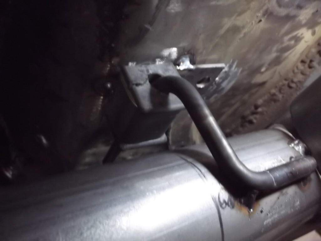
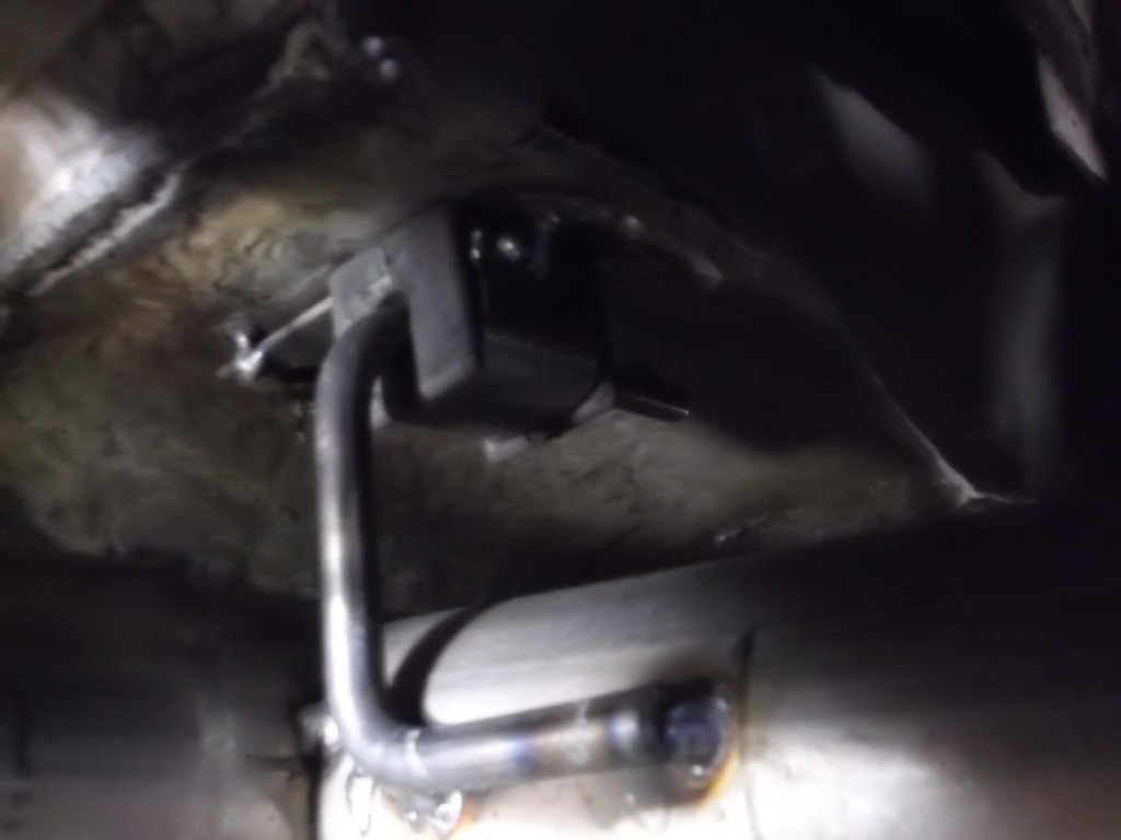
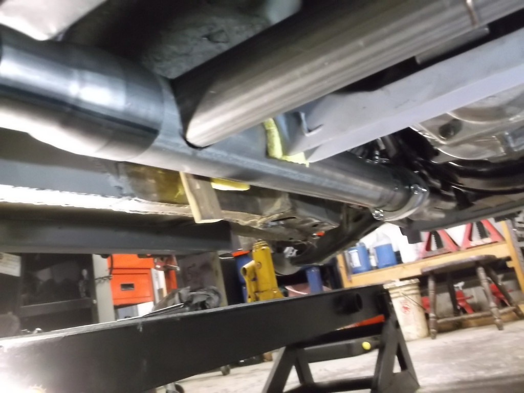
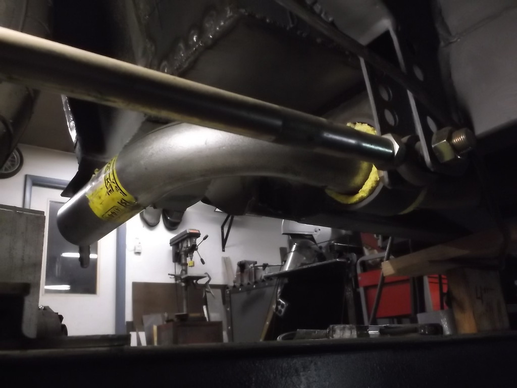
Here is H-pipe installed and finally supported on its own. All tucked up nice and tight.
Right side extension pipe

balance tube trimmed up. Inner marker lines show where outer wall of extension pipe will be.

Balance tube leveled and tacked in place.

And a look from inside the extension pipe.

I decided to cut the balance tube in half and use a band clamp to hold it together. This allows me to adjust the width at the back of the extension pipes and also lets me take one side down at a time or both sides down together.

I picked up some nifty exhaust hangers at Summit Racing part number APH-339816S. The rod is 3/8 diameter and the straight portion is 10" long. Also comes with a rubber insulator in a nice small metal bracket that can be bolted or welded to frame or floor pan. Just $3.40 each!!!
<a href="http://s1309.photobucket.com/user/83RDRACR/media/engine%20and%20drive%20train/AP%20exhaust%20hanger_zpsognqnfl9.jpg.html" target="_blank"><img src="http://i1309.photobucket.com/albums/s627/83RDRACR/engine%20and%20drive%20train/AP%20exhaust%20hanger_zpsognqnfl9.jpg" border="0" alt=" photo AP exhaust hanger_zpsognqnfl9.jpg"/></a>
I used one hanger for each side of my H-pipe assembly, that way if I took just one side down for some reason the other side would stay in place. I left the top section of rod fairly long and straight and used a torch to heat and bend the two 90's. I made sure I left room between the hangers to allow me to slide the band clamp off to either side.


Here is H-pipe installed and finally supported on its own. All tucked up nice and tight.

Joined: Sep 1999
Posts: 4,353
Likes: 308
From: NJ
Car: 92 Firebird
Engine: 4.8 LR4
Transmission: T56
Axle/Gears: 3.45 9 Bolt
Re: Home brew road racer
I suppose if you don't plan on going EFI, it won't be a problem for a carburetor
Thread Starter
Senior Member
Joined: Aug 2007
Posts: 682
Likes: 45
Re: Home brew road racer
Scooter, I guess you are referring to the possibility of fresh air being drawn into the splice connections and giving a false reading to a wide band o2 sensor? If I ever go EFI that might be a concern IF they leak but honestly you cant believe how tight the fit was. I had to persuade the top tubes into the sleeves wit a 3lb brass hammer. Like I said before we will just have to see when I get it running (hopefully not too long from now).
A little off subject, but I see you owned a Solstice. I always liked the look of the car. Any comment on it performance, handling etc.?
I always appreciate your comments. Please continue to look over my post and point out anything that you might consider a safety or performance issue.
Dave
A little off subject, but I see you owned a Solstice. I always liked the look of the car. Any comment on it performance, handling etc.?
I always appreciate your comments. Please continue to look over my post and point out anything that you might consider a safety or performance issue.
Dave
Thread Starter
Senior Member
Joined: Aug 2007
Posts: 682
Likes: 45
Re: Home brew road racer
Norm, glad you are still following along. Its been a long road but at least I am installing the exhaust system and not building basic framework anymore so some progress has been made.
I don't have any loose, slip-fit connections in the exhaust, all are welded or clamped. I did run into a problem with the hangers though. For convenience I had the hangers on the H-pipe slide in from the rear and the hangers on the muffler slide in from the front. This arrangement would not let me disassemble the system as neither section could move far enough to slide out of the hanger bracket. Since the muffler hangers had to slide in front to rear, I had to cut off the H-pipe hangers and remount them to also slide in front to rear. All of the hangers mount in a fore-aft orientation to allow the the pipes to "grow" or lengthen with heat. The balance tube for the H-pipe is split into two pieces and clamped with a butt connection band clamp. This is pretty rigid but similar to many OE and aftermarket systems I have seen.
I don't have any loose, slip-fit connections in the exhaust, all are welded or clamped. I did run into a problem with the hangers though. For convenience I had the hangers on the H-pipe slide in from the rear and the hangers on the muffler slide in from the front. This arrangement would not let me disassemble the system as neither section could move far enough to slide out of the hanger bracket. Since the muffler hangers had to slide in front to rear, I had to cut off the H-pipe hangers and remount them to also slide in front to rear. All of the hangers mount in a fore-aft orientation to allow the the pipes to "grow" or lengthen with heat. The balance tube for the H-pipe is split into two pieces and clamped with a butt connection band clamp. This is pretty rigid but similar to many OE and aftermarket systems I have seen.
Joined: Sep 1999
Posts: 4,353
Likes: 308
From: NJ
Car: 92 Firebird
Engine: 4.8 LR4
Transmission: T56
Axle/Gears: 3.45 9 Bolt
Re: Home brew road racer
A little off subject, but I see you owned a Solstice. I always liked the look of the car. Any comment on it performance, handling etc.?
I always appreciate your comments. Please continue to look over my post and point out anything that you might consider a safety or performance issue.
Dave
I always appreciate your comments. Please continue to look over my post and point out anything that you might consider a safety or performance issue.
Dave
Yeah, I had a Solstice. It was a fun car to drive, it needed to have the torque management turned down though, but I never did it. It was a little "slow" off the start unless you almost launched it, but the car was so light that there was no weight over the rear end. If there was any moisture on the road and you weren't paying attention you could spin the car out EASILY, even with the torque management where it was from the factory, so I think GM did it like that for safety since most people have no idea what to do when the rear comes around.
I made the mistake of selling it cheap to a friend and still went with the sale, even though my cousin said I was making a mistake and I told them I wanted to buy it back if they ever were going to sell it. Then when I found out they were selling it I asked to buy it back, but they really screwed me because they found out they could get double what I sold it to them for.
If I stay where I am instead of moving I may buy another one, a 2009 GXP Hard top or at least a hard top and put an LSx into it with a 6 speed, like they did in Hot Rod Magazine.
Thread Starter
Senior Member
Joined: Aug 2007
Posts: 682
Likes: 45
Re: Home brew road racer
Haven't posted for a few weeks but still plugging away. I had to sell some unneeded parts to pay for the other side of the exhaust and an aluminum water pump. The exhaust is nearly finished and tucks up nicely under the raised floors. Need to finish welding a few pipes and hangers. Water pump is to arrive late this week. Once that is here I can remount the alt. and p/s pump, get a couple belts and make hoses for p/s pump.
I have started the wiring. Trying to use as much of factory harness as possible for simplicity and cost. It is in great condition and not all cut up and spliced together. Removed all of a/c and heater blower wiring from the engine harness and added a couple wires for the low and high speed temp sensors. Front lighting harness is unchanged except for headlight sockets. I had to splice in sockets for 9005 and 9006 bulbs. I will be running the low beams as daytime running lights/low beam headlights like my chevy truck, so they will be on anytime key is in "run" position. High beams will work from lever on steering column.
The front turn signal/parking light assemblies were broken in the accident and I plan on using those openings for brake ducts. I am thinking of drilling a hole in the bottom of the headlight assembly just left of center and screw the socket in there. It should be visible even with low beam on and not usually needed to be seen when hi-beams are on.
I will post pictures soon.
Scooter, thanks for your feedback on the Solstice. A 2007 just showed up in the local paper but its only a pipe dream for me. I will have to be content with building my version of a third gen.
Thread Starter
Senior Member
Joined: Aug 2007
Posts: 682
Likes: 45
Re: Home brew road racer
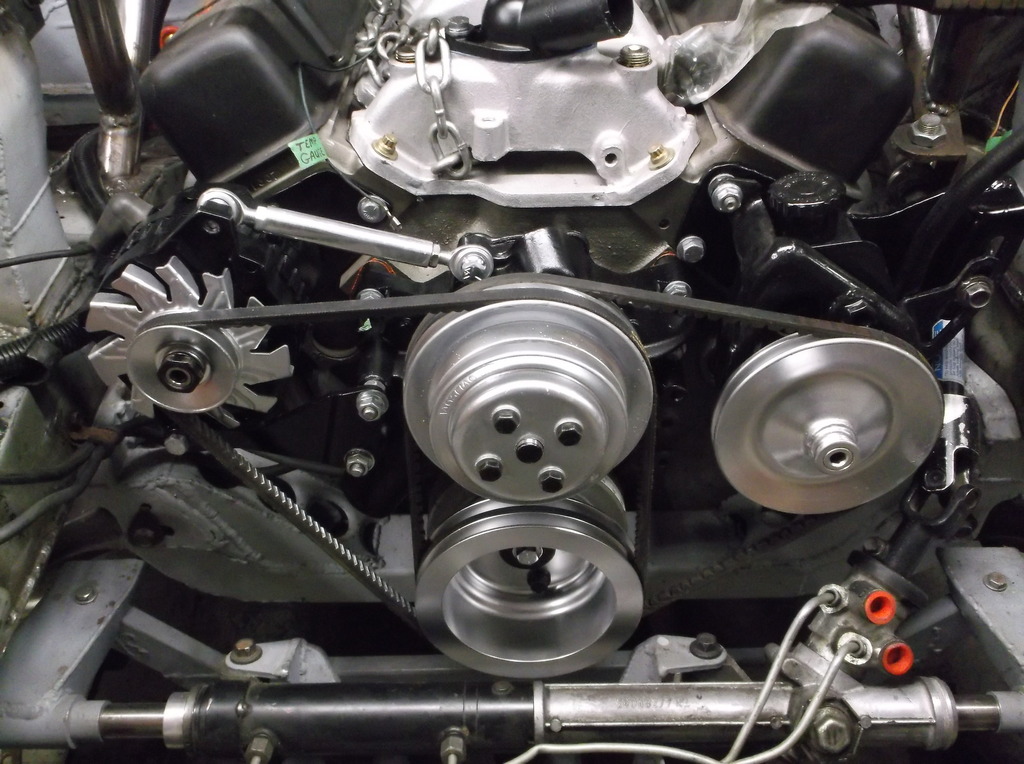
I bought the aluminum water pump off ebay from demotor performance. It seems like a pretty decent part as far as casting and machine work. They did post a warning about possible leak on rear cover gasket which I thought was a thoughtful and professional touch. Before I installed I removed and resealed the cover. It looks like they used household plumbers putty for gasket sealer on the cover. I cleaned up and painted all of my homemade brackets and tried to make the front of the motor look "finished".
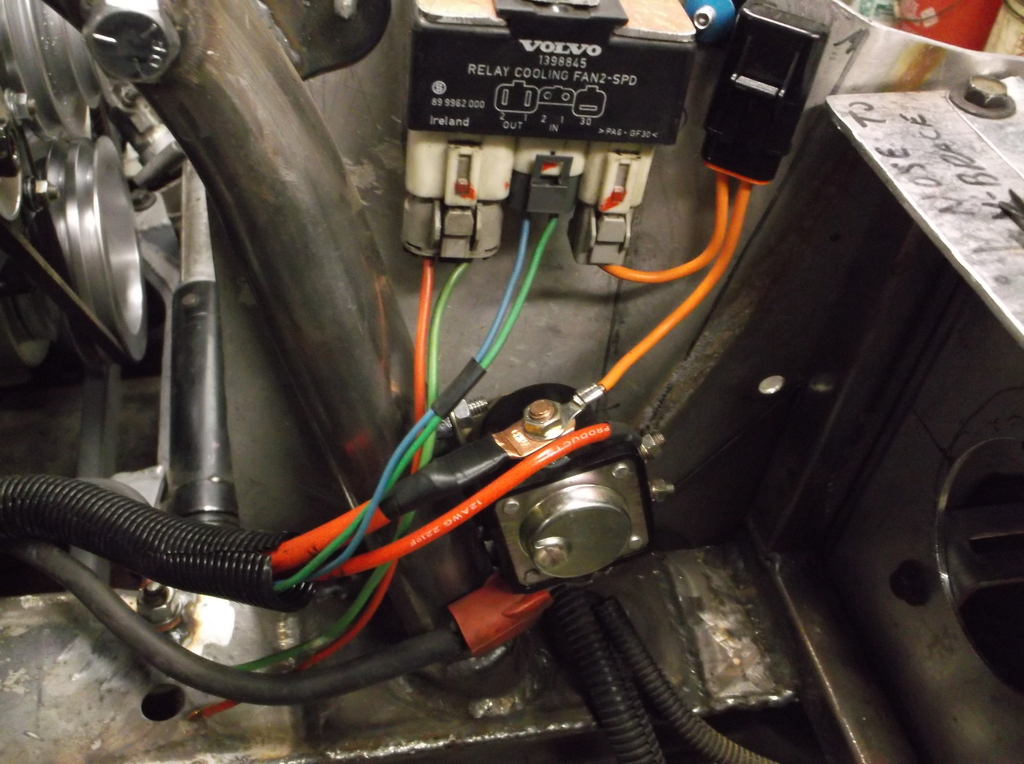
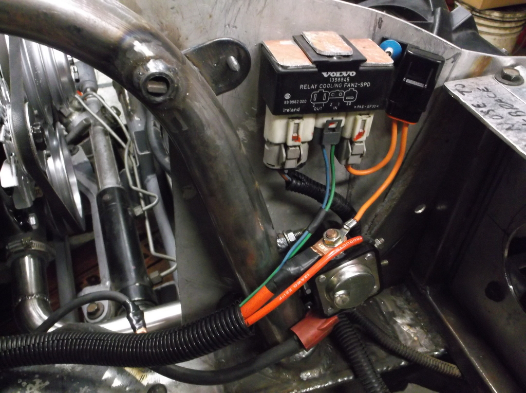
Worked more on the engine wiring. Not much here except the ignition and electric fans and sensor wires. I am running a remote "hot start" solenoid to energize the starter. I mounted the starter forward of the engine to keep cable to starter away from the headers as much as possible. Also used hot side of solenoid for battery power to fan relays. Fans will be able to run after engine is off if temps dictate.
Added a 30 amp fuse to fan circuit. I have been able to take apart the Volvo connectors and solder in new wires avoiding multiple splice connections.
The fans and temp gauge will require a total of 4 sensors; one for the gauge, one for the temp warning light, and one each for low and high speeds. Good thing my intake manifold has 4 water ports! In addition I will need 3 sensors plumbed into the oil pressure line; oil pressure gauge, ;low oil pressure warning light and a fuel pump cutoff switch. Thats a lot of sensors and wiring for a couple gauges and fans!
I will be mounting the battery behind the passenger seat. Positive cable will run to a master cut off switch mounted in center of dash above the shifter and from there to a battery bulkhead connector just above the right frame rail. On the engine side of the connector are the battery cable to starter solenoid, the charging wire from the battery post on the alternator and a power feed back to the factory bulkhead connector by the brake master cylinder. This power feed was originally two wires protected by fusible links connected to a single lug terminal and attached to the battery stud on the starter. I replaced the two fusible links with a single 40 amp maxi fuse that I mounted to the firewall with a simple aluminum bracket.
Battery bulkhead connector
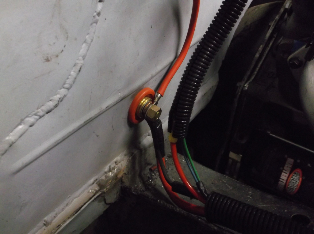
40 amp Maxi fuse.
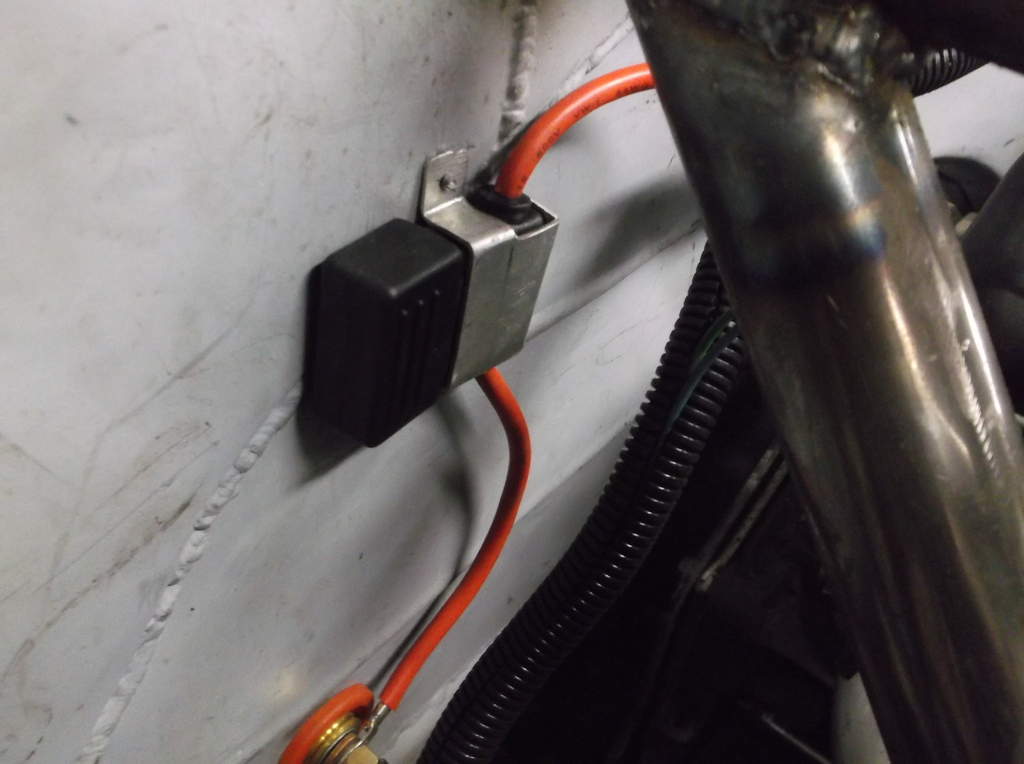
To make sure I have a good chassis ground I welded a 3/8 bolt to the frame rail.
I can't stand seeing cars with a tangled "bird's nest" of wires under the hood or dash, so trying to keep as clean and simple as possible.

Worked more on the engine wiring. Not much here except the ignition and electric fans and sensor wires. I am running a remote "hot start" solenoid to energize the starter. I mounted the starter forward of the engine to keep cable to starter away from the headers as much as possible. Also used hot side of solenoid for battery power to fan relays. Fans will be able to run after engine is off if temps dictate.
Added a 30 amp fuse to fan circuit. I have been able to take apart the Volvo connectors and solder in new wires avoiding multiple splice connections.

The fans and temp gauge will require a total of 4 sensors; one for the gauge, one for the temp warning light, and one each for low and high speeds. Good thing my intake manifold has 4 water ports! In addition I will need 3 sensors plumbed into the oil pressure line; oil pressure gauge, ;low oil pressure warning light and a fuel pump cutoff switch. Thats a lot of sensors and wiring for a couple gauges and fans!
I will be mounting the battery behind the passenger seat. Positive cable will run to a master cut off switch mounted in center of dash above the shifter and from there to a battery bulkhead connector just above the right frame rail. On the engine side of the connector are the battery cable to starter solenoid, the charging wire from the battery post on the alternator and a power feed back to the factory bulkhead connector by the brake master cylinder. This power feed was originally two wires protected by fusible links connected to a single lug terminal and attached to the battery stud on the starter. I replaced the two fusible links with a single 40 amp maxi fuse that I mounted to the firewall with a simple aluminum bracket.
Battery bulkhead connector

40 amp Maxi fuse.

To make sure I have a good chassis ground I welded a 3/8 bolt to the frame rail.

I can't stand seeing cars with a tangled "bird's nest" of wires under the hood or dash, so trying to keep as clean and simple as possible.


Junior Member
Joined: Jul 2016
Posts: 4
Likes: 0
From: Stouffville, North of Toronto
Car: 2013 RAM, 1991 GTA
Engine: 5.0
Transmission: T5
Axle/Gears: Factory?
Re: Home brew road racer
Great work on your project, looks like you are starting to see the light at the end of the tunnel!
Thread Starter
Senior Member
Joined: Aug 2007
Posts: 682
Likes: 45
Re: Home brew road racer
Bevo66, Thanks for following along. Yeah definitely seeing it finally coming together. It makes all the planning, designing, and fab work worthwhile. The car is very close to what my original vision of what the car could/should be. I am just hoping the performance and handling will meet my expectations.
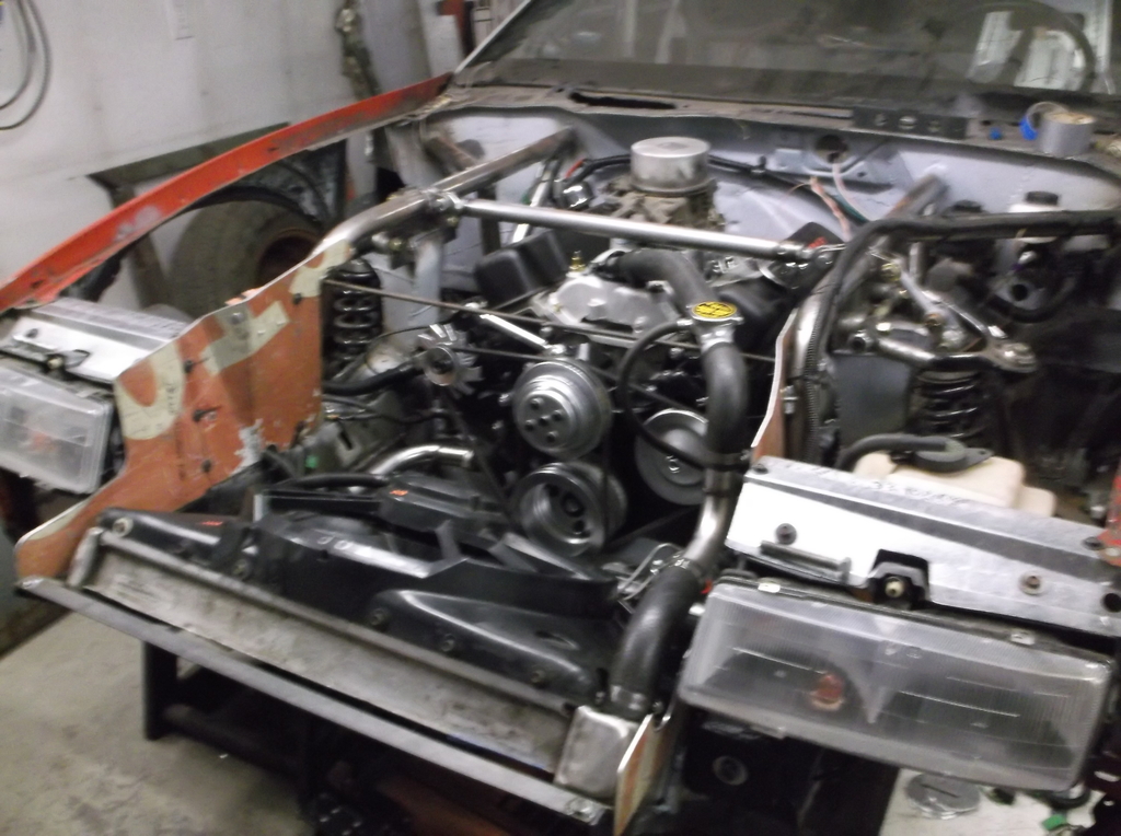
Anyway got a little more done the last couple days. The engine compartment is just about finished except for brake and fuel lines.
Mounted radiator and fan, rewired fan controller. The Volvo fan controller has modular weatherpack connectors that allowed me to disassemble them and remove the Volvo lead wires and crimp/solder in my own wiring. this eliminated any splice connections.
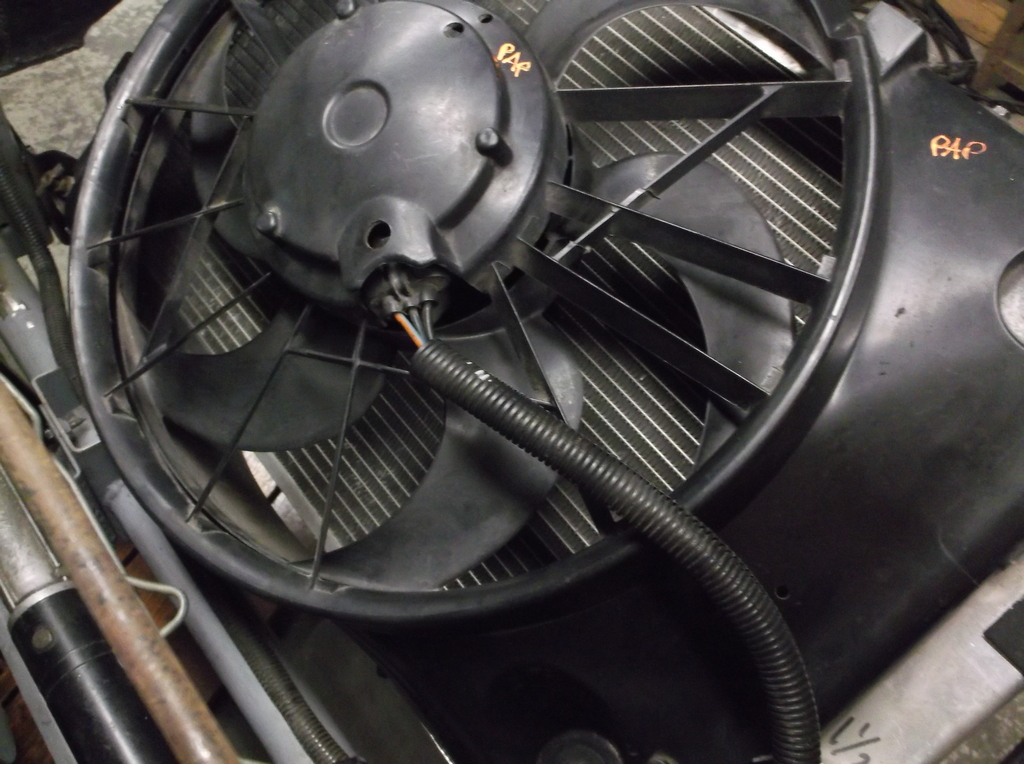
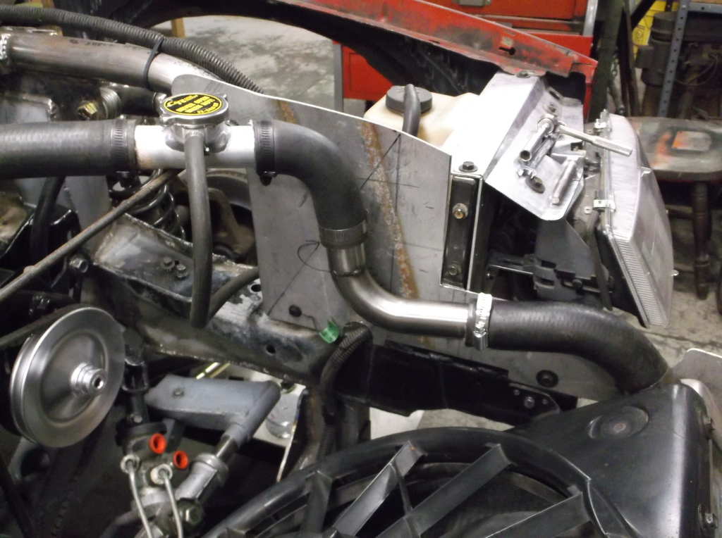
Finalized radiator hose routing.
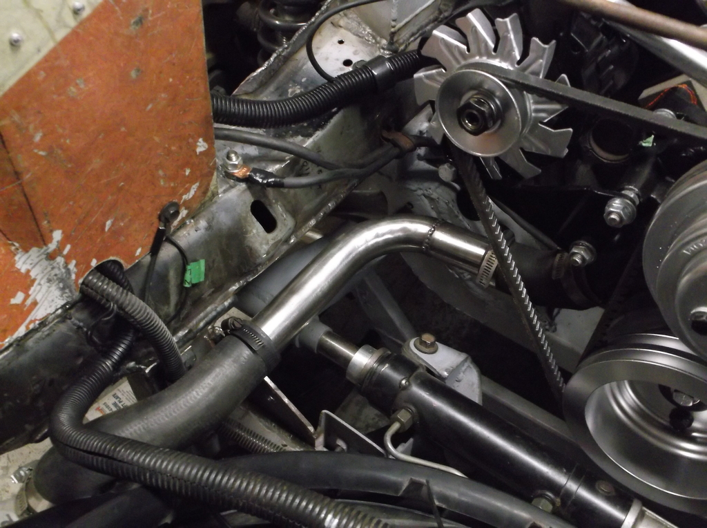
Picked up some metric o-ring to -6AN adapter fittings for the P/S connections. Rack used 18mm x 1.5 and 16mm x 1.5 and third gen p/s pump used 16mm x 1.5. Also because 3rd gen pump was valved for a gear box and not rack and pinion the output pressure is too high at about 1200psi. I got a Borgenson shim kit for the pressure valve and used 4 shims to reset max pressure to about 850psi. This kit is very inexpensive at about $18.00 from Summit and real easy to install. If the 850psi turns out to be too low I can remove a shim and kick the pressure up to approximately 1000psi.
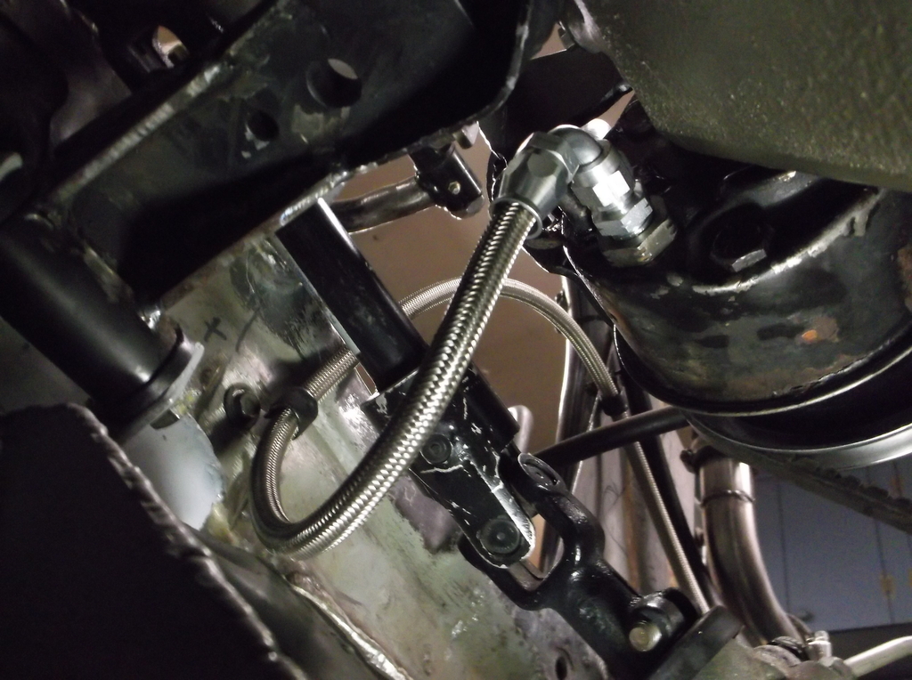
I made my own p/s lines. Pressure hose is PTFE (teflon lined) high pressure hose and STEEL fittings. Return hose is a low pressure hydraulic hose rated at 350psi and is pushed over barb fittings and secured with hose clamps.
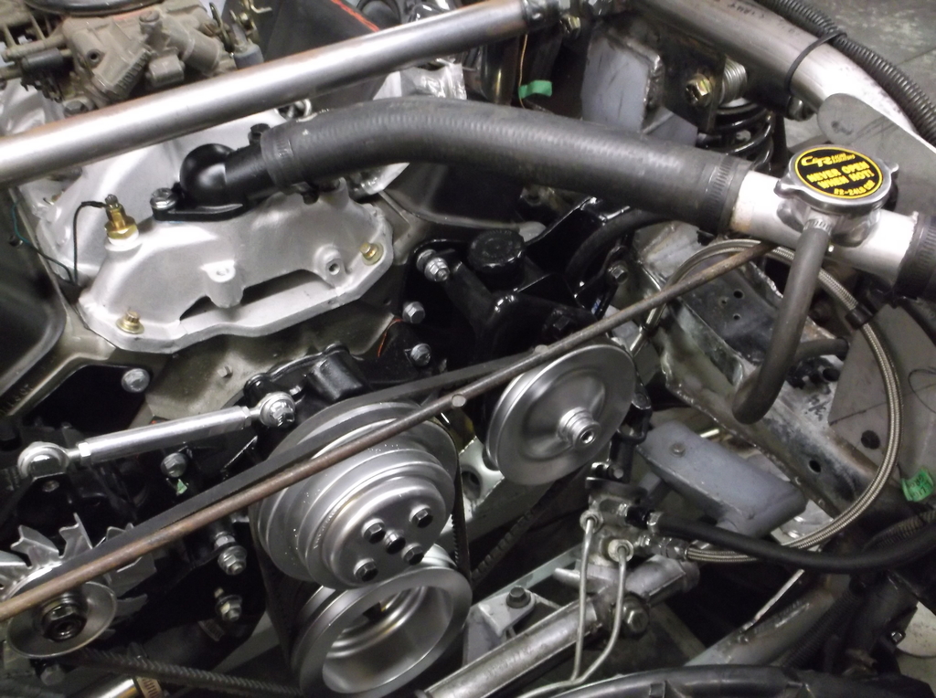
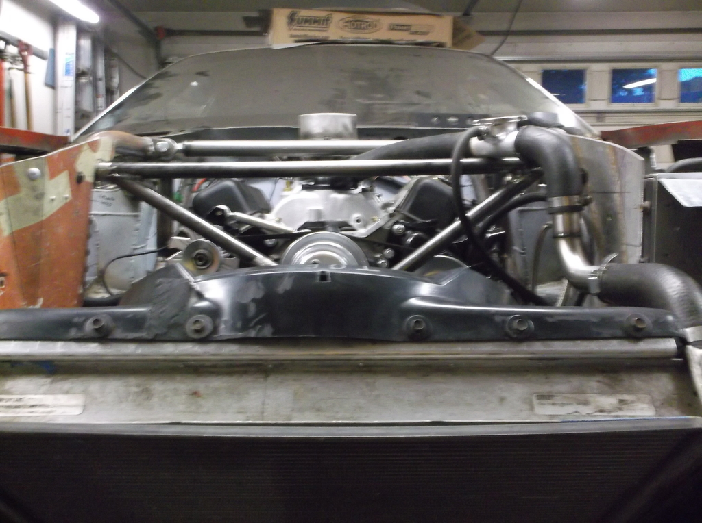
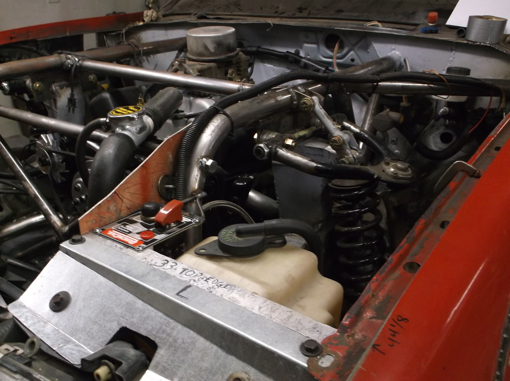
Reinstalled the X-brace. It went in without having to disconnect any hoses or wiring. It makes the front of the engine look a little crowded but all hoses and accessories are still very accessible.
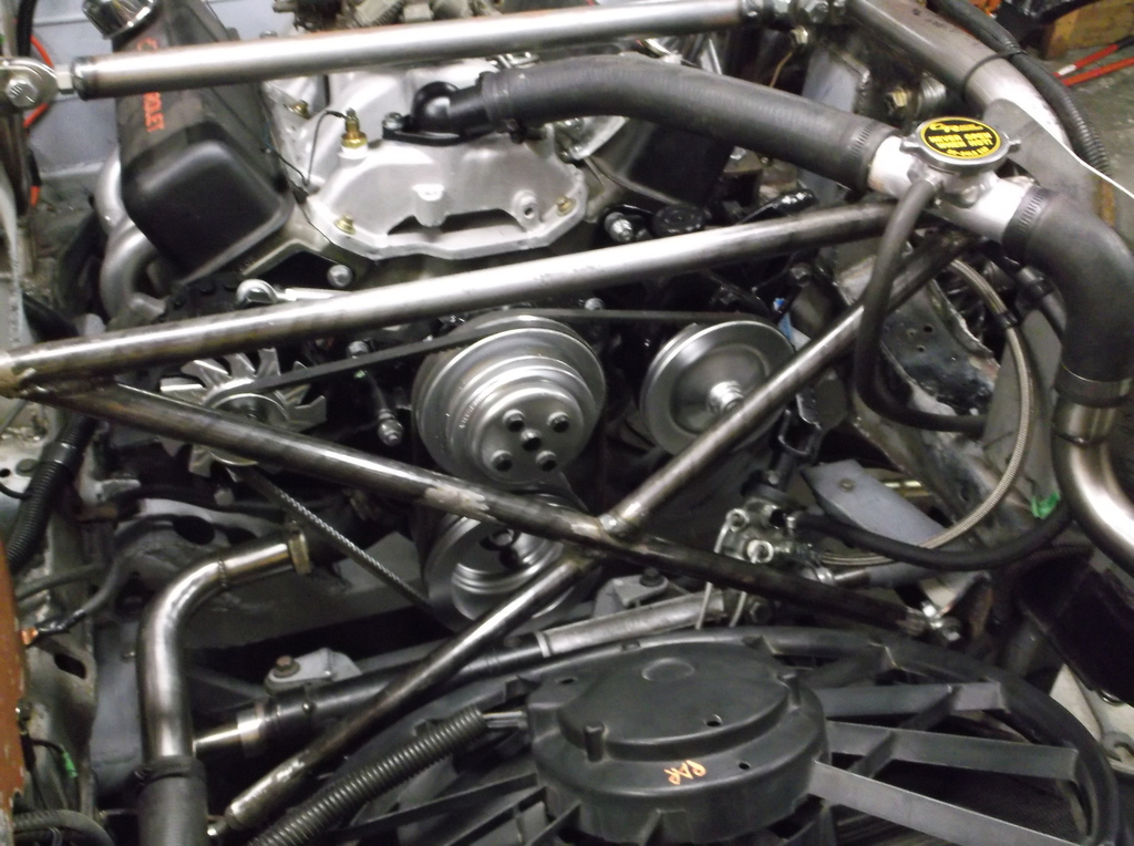
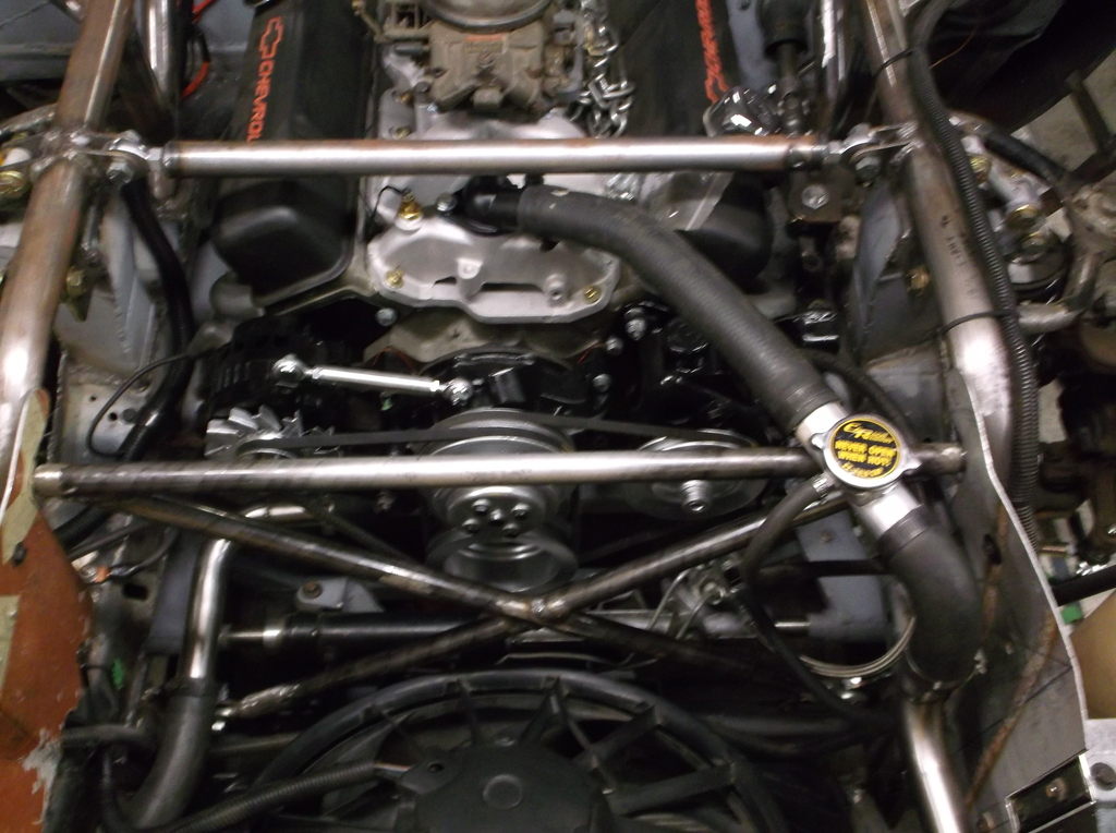
Just thought this view looked cool.
Anyway got a little more done the last couple days. The engine compartment is just about finished except for brake and fuel lines.
Mounted radiator and fan, rewired fan controller. The Volvo fan controller has modular weatherpack connectors that allowed me to disassemble them and remove the Volvo lead wires and crimp/solder in my own wiring. this eliminated any splice connections.


Finalized radiator hose routing.


Picked up some metric o-ring to -6AN adapter fittings for the P/S connections. Rack used 18mm x 1.5 and 16mm x 1.5 and third gen p/s pump used 16mm x 1.5. Also because 3rd gen pump was valved for a gear box and not rack and pinion the output pressure is too high at about 1200psi. I got a Borgenson shim kit for the pressure valve and used 4 shims to reset max pressure to about 850psi. This kit is very inexpensive at about $18.00 from Summit and real easy to install. If the 850psi turns out to be too low I can remove a shim and kick the pressure up to approximately 1000psi.
I made my own p/s lines. Pressure hose is PTFE (teflon lined) high pressure hose and STEEL fittings. Return hose is a low pressure hydraulic hose rated at 350psi and is pushed over barb fittings and secured with hose clamps.


Reinstalled the X-brace. It went in without having to disconnect any hoses or wiring. It makes the front of the engine look a little crowded but all hoses and accessories are still very accessible.


Just thought this view looked cool.

Thread Starter
Senior Member
Joined: Aug 2007
Posts: 682
Likes: 45
Re: Home brew road racer
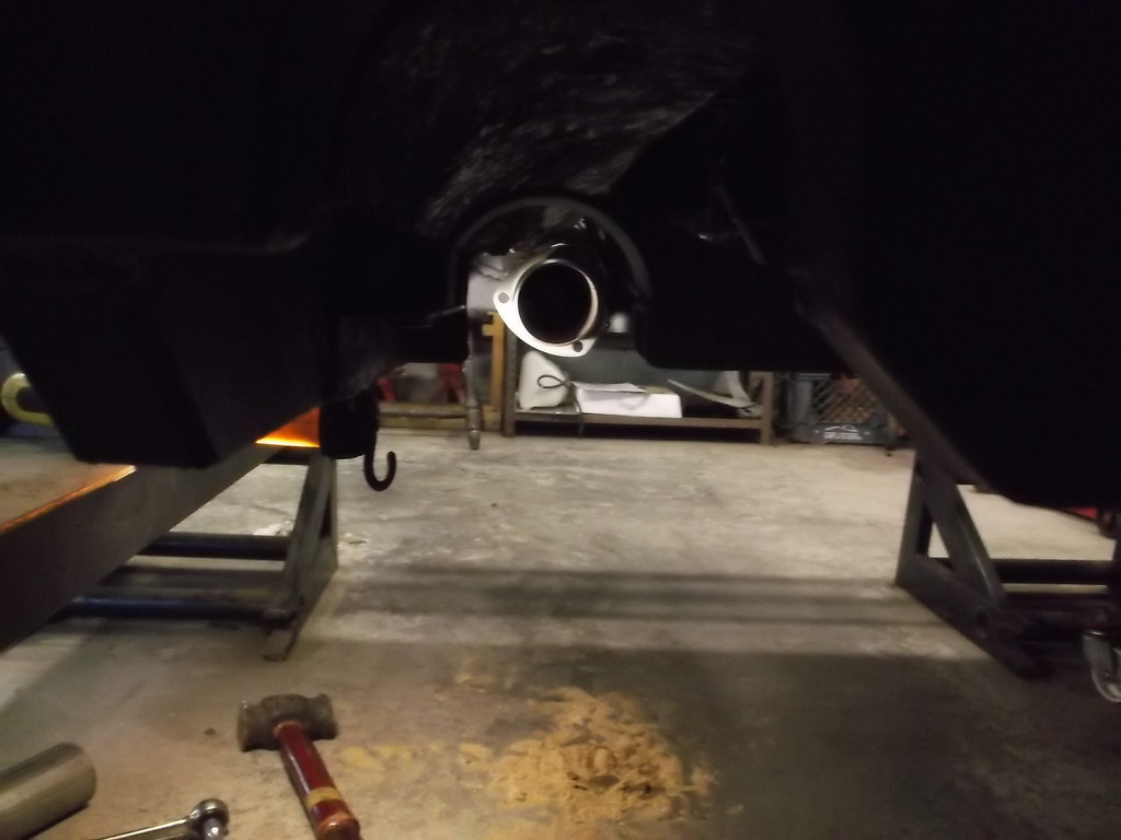
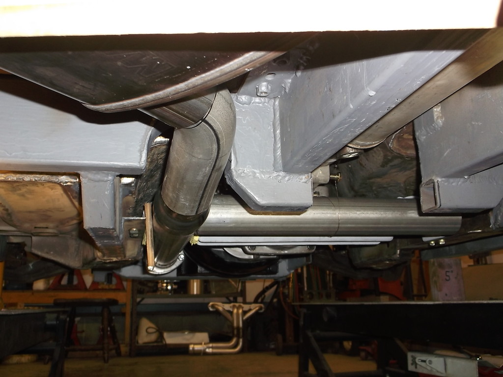
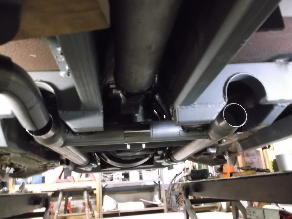
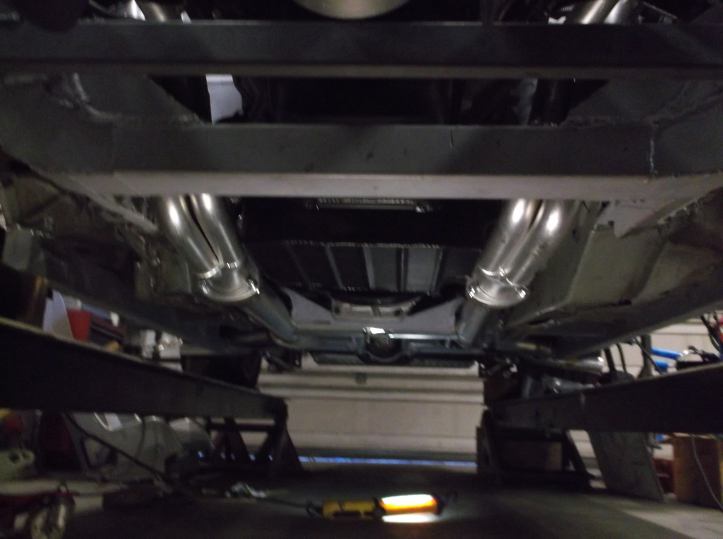
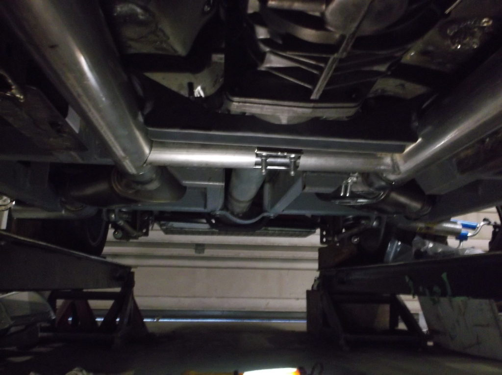
Tried to take some pics of the bottom of the car. Cant believe how "clean" it is and how unobtrusive the exhaust system is. It wouldn't be hard to do a full belly pan is the car ever got fast enough to benefit from them.
The pictures are a little dark and don't do it justice.
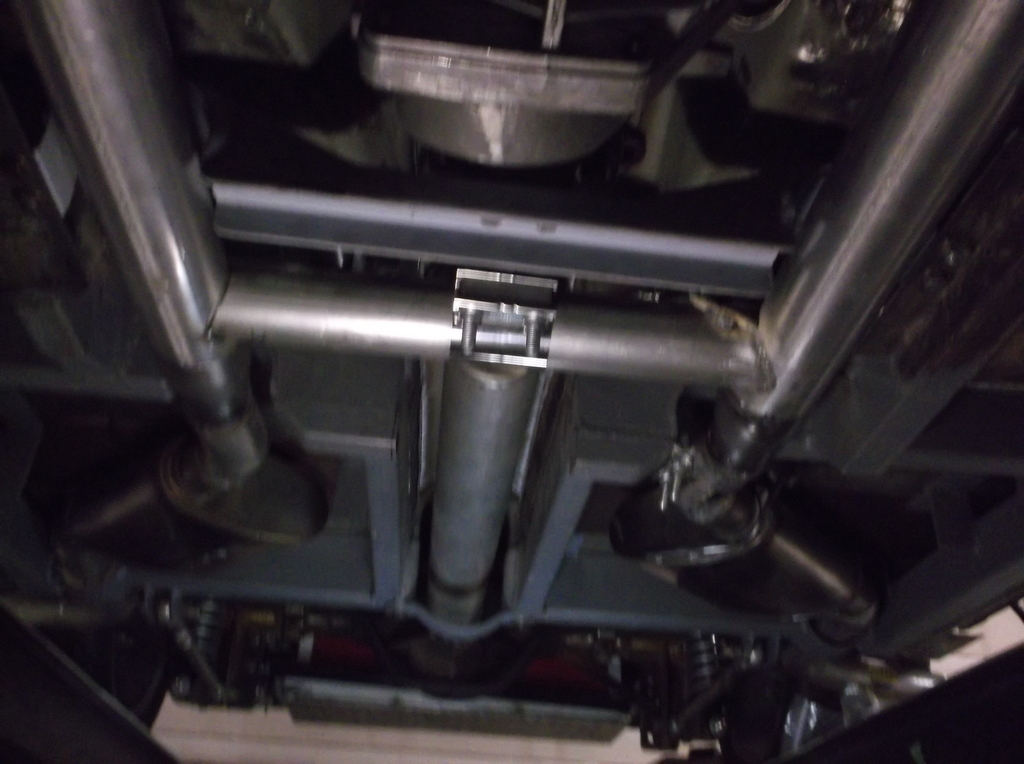
Cant wait to hear it fire up. Should be just a couple weeks now.
The pictures are a little dark and don't do it justice.


Cant wait to hear it fire up. Should be just a couple weeks now.
Member
Joined: May 2001
Posts: 438
Likes: 1
From: state of confusion
Car: '08 Mustang GT
Engine: 4.6L
Transmission: � � 0 . . . |-|-|
Axle/Gears: 8.8", 3.55
Re: Home brew road racer
Really nice to see it getting there.
Any chance of getting a sound track of it posted here when you do fire it up?
Norm
Any chance of getting a sound track of it posted here when you do fire it up?
Norm
Thread Starter
Senior Member
Joined: Aug 2007
Posts: 682
Likes: 45
Re: Home brew road racer
Hey Norm, yeah its great to be putting the little pieces on finally. It is still a long way off from being road worthy, mainly due to lack of funds since I had to quit working last year. Getting the engine running is probably just a couple weeks away. I will be sure to get a start up video with sound track of engine/exhaust.
I too am curious as to how my exhaust system will sound. The much acclaimed exhaust sound of the Fox body mustangs was due in part to running an "H" pipe instead of the more popular X pipe. With the my exhaust exiting out the rocker panel just ahead of the rear tire I am hoping for a more moderate/mellow exhaust tone versus a more raspy sound.
I sincerely appreciate the interest you and many others have shown in my project and it really helps keep me motivated to see it through to completion.
Dave
Junior Member
Joined: Jul 2016
Posts: 4
Likes: 0
From: Stouffville, North of Toronto
Car: 2013 RAM, 1991 GTA
Engine: 5.0
Transmission: T5
Axle/Gears: Factory?
Re: Home brew road racer
I think the sound will be fantastic, adding the ground shaking under the car will be a 3D experience!
Amazing how clean it looks with everything tucked up like that, great job!
Amazing how clean it looks with everything tucked up like that, great job!
Thread Starter
Senior Member
Joined: Aug 2007
Posts: 682
Likes: 45
Re: Home brew road racer
Bevo66, thanks again for the props. With the exhaust exiting out through the gfx just behind the doors the sound will definitely be heard inside the car. With no a/c the windows will be down most of the time as well. Just hoping for no droning sound at cruise or part throttle. I can insert baffles into the pipes to try and tune the sound if it is too obnoxious.
https://www.summitracing.com/oh/sear...aillocation=oh
https://www.summitracing.com/oh/sear...aillocation=oh
Thread Starter
Senior Member
Joined: Aug 2007
Posts: 682
Likes: 45
Re: Home brew road racer
Ok, this is post #500!!! Will it ever end? The exhaust is finally finished, all pipes welded and all hangers in place. This took a lot more time than I thought it would. Getting the hangers in the proper location to hold the exhaust in place and still allow for easy install and removal was a lot of trial and error (more error).
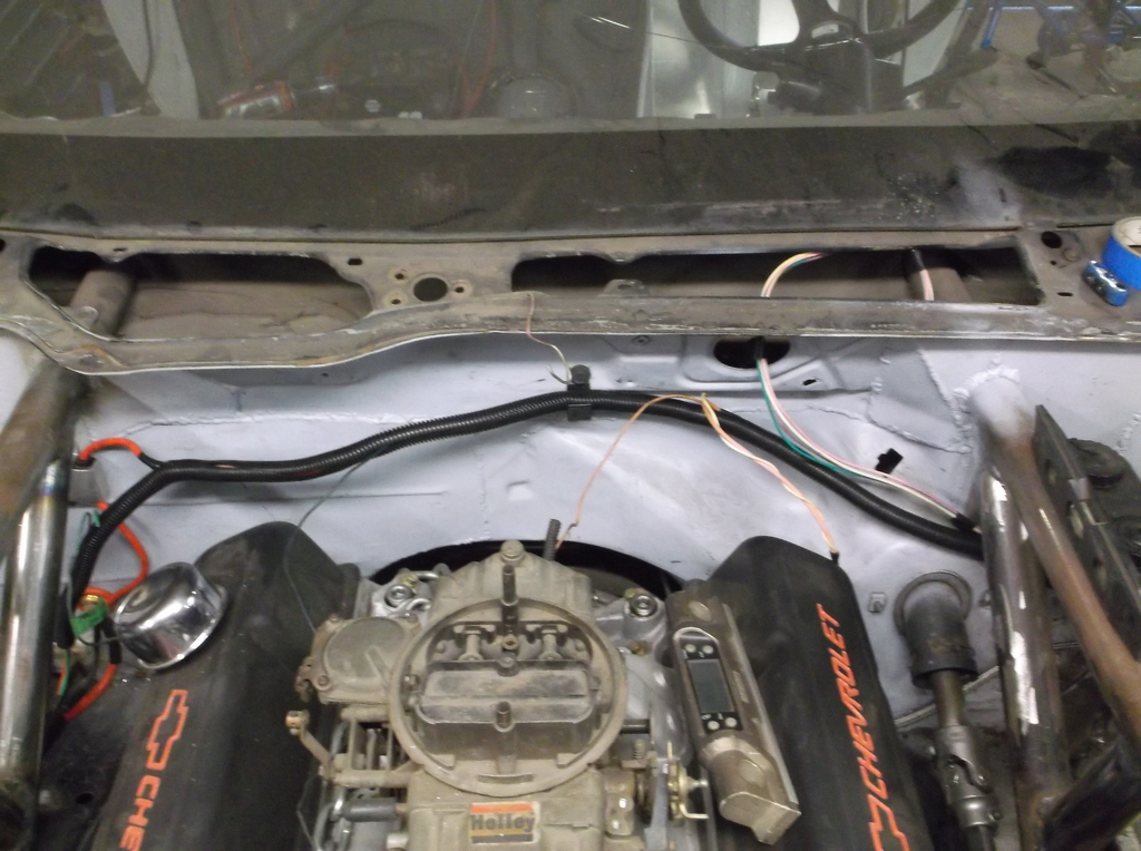
Worked more on the wiring. Front of car should be about done. Got all lights working and the relocated turn signals are very visible with the low beams on. Also they don't seem to cause a shadow with the high beams on.
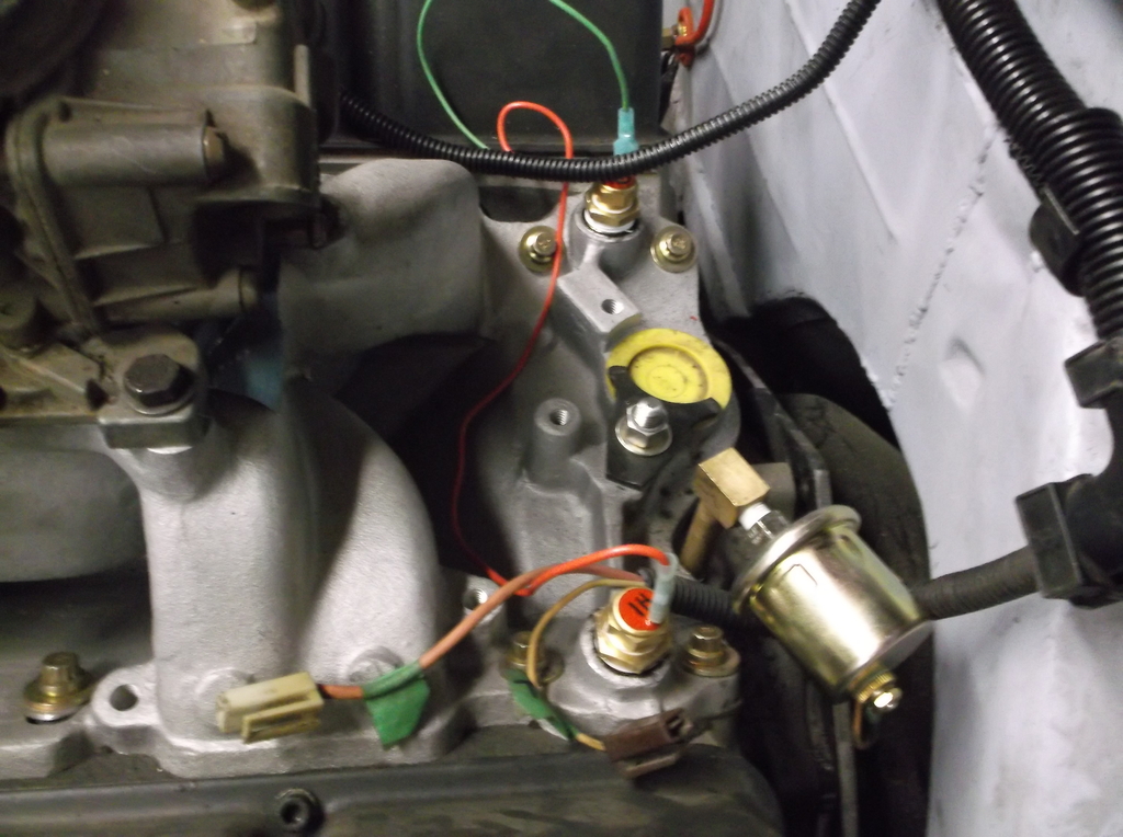
The fan sensors arrived and those are wired in now. I am running a 180* stat and have the low speed fan coming on at 195* and the high speed fan at 210*. The temp warning light in the dash will flash at 235*
Hi and low speed sensors mounted in water ports at rear of intake manifold. Oil pressure sensor wired in as well.
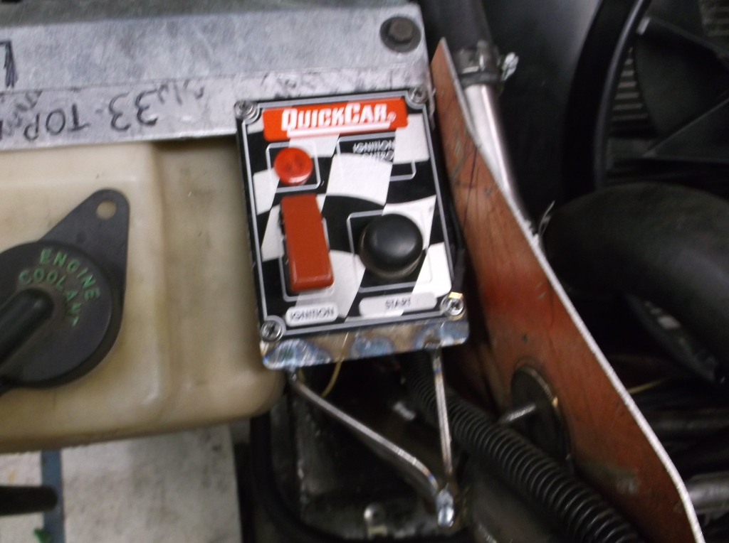
I added a remote start switch panel to the left headlight support. This will allow me to bump the engine over or start the engine from outside the car. This will come in handy when tuning the car at home or making adjustments at the track. From this location I can easily see the timing marks, reach #1 spark plug or work the throttle.
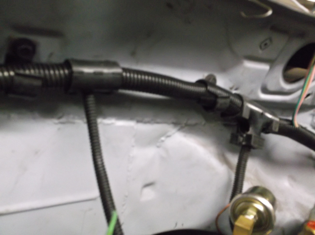
Since I saved all the wiring from the Camaro and my old '95 C1500 truck I have plenty of the convoluted tubing to encase the wiring and the factory connectors and tees. This made keeping the wiring neat and tidy, easy and cheap.
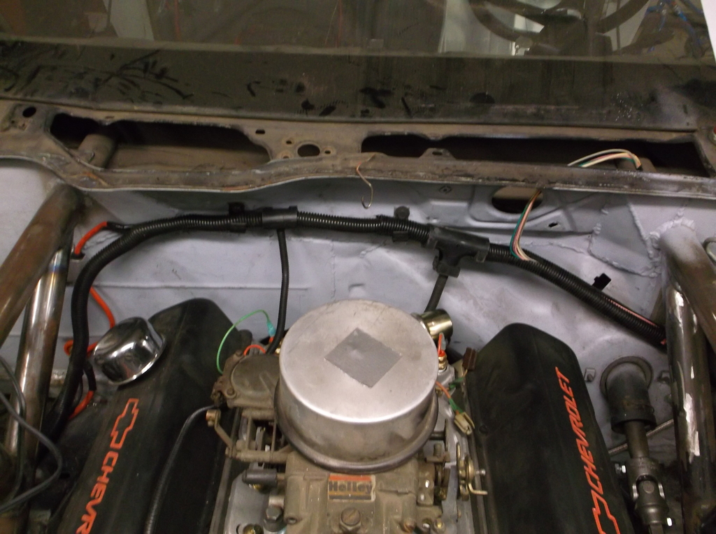
Still need to get the fuel lines run and a regulator installed. getting closer and closer. Getting the engine fired up will be a big step forward and a big moral booster.
Worked more on the wiring. Front of car should be about done. Got all lights working and the relocated turn signals are very visible with the low beams on. Also they don't seem to cause a shadow with the high beams on.
The fan sensors arrived and those are wired in now. I am running a 180* stat and have the low speed fan coming on at 195* and the high speed fan at 210*. The temp warning light in the dash will flash at 235*
Hi and low speed sensors mounted in water ports at rear of intake manifold. Oil pressure sensor wired in as well.

I added a remote start switch panel to the left headlight support. This will allow me to bump the engine over or start the engine from outside the car. This will come in handy when tuning the car at home or making adjustments at the track. From this location I can easily see the timing marks, reach #1 spark plug or work the throttle.


Since I saved all the wiring from the Camaro and my old '95 C1500 truck I have plenty of the convoluted tubing to encase the wiring and the factory connectors and tees. This made keeping the wiring neat and tidy, easy and cheap.


Still need to get the fuel lines run and a regulator installed. getting closer and closer. Getting the engine fired up will be a big step forward and a big moral booster.