
Home brew road racer


Junior Member
Joined: Apr 2015
Posts: 3
Likes: 0
Re: Home brew road racer
Wow! you sir, are a most impressive man. You dream big; at the same tine you're able to articulate those dreams into action and reality. On top of that, you're generous enough to share your progress and knowledge with anyone interested with the most in-depth, interesting, and helpful buildup I've ever read . You've shared your setbacks and design epiphanies honestly, and openly invite and incorporate your followers comments and opinions. thank you for taking the time to share your knowledge and expertise.
I just traded into an beater 86 IROC and found your thread while researching the possibilities of my new toy. In fact, I joined tgo solely because of this thread. I've got a similar background as you with about 40 years of wrenching, most of it on a budget, and I too have fielded competitive dirt track race cars.
Your build has definitely influenced plans for my 86. Have you (or any tgo members) ever considered an AWD 3rd gen buildup? It seems like the obvious next step beyond your project plans and your project appears to lay a perfect foundation. I'm thinking a Bowtie response to Ken Block's outrageously awesome '65 Hoonigan Mustang here. Is such a build even feasible with GM hardware?
Thanks again and congratulations; you've got another faithful follower.

Junior Member
Joined: Apr 2015
Posts: 3
Likes: 0

Thread Starter
Senior Member

Joined: Aug 2007
Posts: 682
Likes: 45
Re: Home brew road racer
flyinbryan, thanks for the props even though its a little over the top. Most of the fab skills have been learn as you go. As an old school mechanic we learned to repair what we could and replace what wasn't repairable. Not working in the autobody trades I did very little welding until my son got into the stock car racing.
I had big ideas for this car that were tempered by my budget and abilities to carry them out. I have had to come up with simple solutions to rather complex problems. The steering rack relocation was by far the biggest challenge and I will not deem that as solved until I can get it down off the ramps and further test it for flex.
As for the 4x4 concept packaging would be pretty tight. Moving the wheels forward would be a must and the engine would have to move back as well to get room for the differential and axles. Driver and passenger would move back to the C pillar to get room for the transfer case. Check out the Summit racing Quadra Deuce for some ideas. This was built around the S10 Cyclone and Typhoon trucks. Here is a link to some pics of the front end.
http://www.ffcars.com/forums/43-off-...euce-pics.html
Again, if any of you that are following along see anything that does not look safe or you think could be made better or safer please speak up. I plan on beating on this car hard and the last part I want to test out is the roll cage.
Thread Starter
Senior Member
Joined: Aug 2007
Posts: 682
Likes: 45
Re: Home brew road racer
I don't think I will have hood clearance issues as the upper a-arm clears the hood by 1/2" at full compression. The arm will probably never travel that far because there will be a 1" bump stop on the coilover that under the hardest hit probably won't compress more than 1/2". If clearance did become an issue I would probably cut the hood out at that point and cover the hole with a small rear facing scoop ala the plymouth superbirds. I am planning on venting the hood anyway.

Supreme Member
iTrader: (3)
Joined: Mar 2015
Posts: 1,072
Likes: 48
From: Minnesota
Car: 84 Z28
Engine: 383 Stroker
Transmission: 700R4
Axle/Gears: 3.73
Re: Home brew road racer
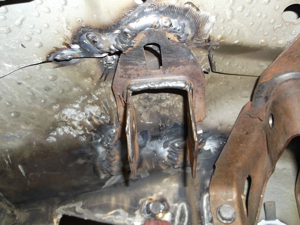
Looks pretty gnarly! Keep those pics coming!! I am curious to see if you can retain your weight prediction.. You think about using aluminum? Suggestion... Welds are very tough... so tough that they break/tear the metal around the weld. This is why you never see welding on frames. usually bolted or riveted. Spot welding on uni-bodys. welds do not flex. Usually when you see some hick in his big old swamp truck his exhaust brackets are broke... cause he welded them to frame.. Also, Be cautious if you are welding by any rubber,plastic. The light will destroy a tire and make rubber/plastic/o-rings/seals brittle as a chip. Cant wait to see the finished product!!!
Thread Starter
Senior Member
Joined: Aug 2007
Posts: 682
Likes: 45
Re: Home brew road racer
From Z28: Welds are very tough... so tough that they break/tear the metal around the weld. This is why you never see welding on frames. usually bolted or riveted. Spot welding on uni-bodys. welds do not flex.
Welds are supposed to be tough. Tube chassis race cares and roll cages are all welded together for that very reason.
Flexing is the problem and the cage and frame work that I have added was added to prevent flex. You cannot have good handling if the chassis flexes as it negates any of the handling improvements you would do to the car such as bigger sway bars, or better shocks and spring. The chassis has to be as stiff as possible to allow the suspension parts to work.
Thread Starter
Senior Member
Joined: Aug 2007
Posts: 682
Likes: 45
Re: Home brew road racer
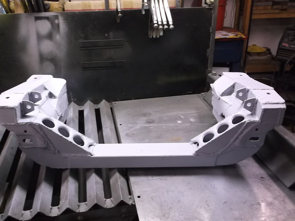
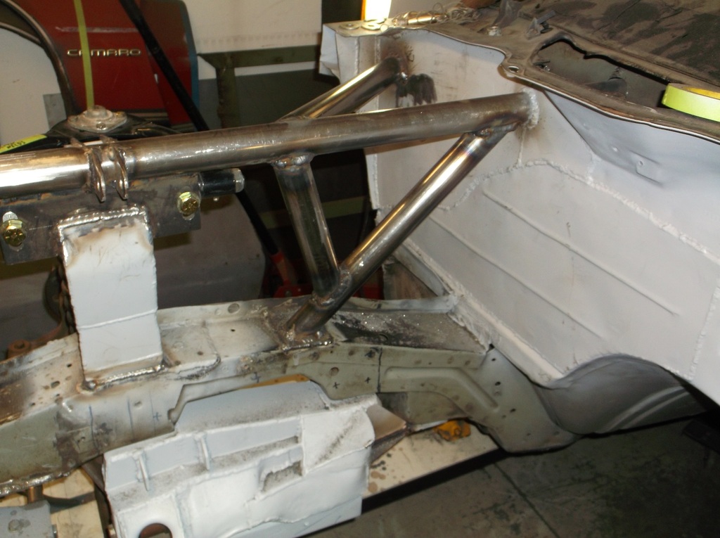
Got some quality time in this past weekend and was able to get the passenger side fabbed up. Everything is still mostly tack welded in. I will fully weld everything when I strip out the k-member and engine later this month.
Here is what i got done.
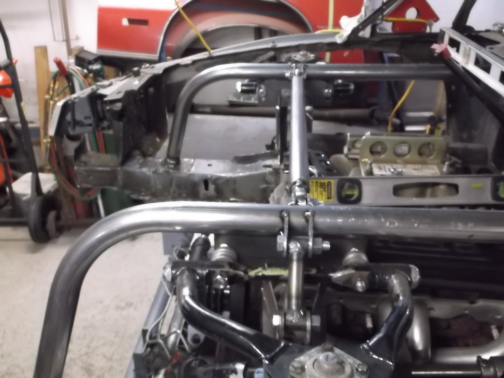
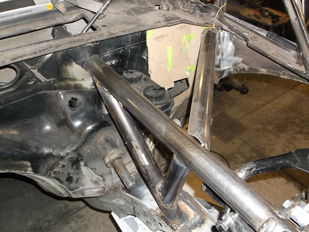
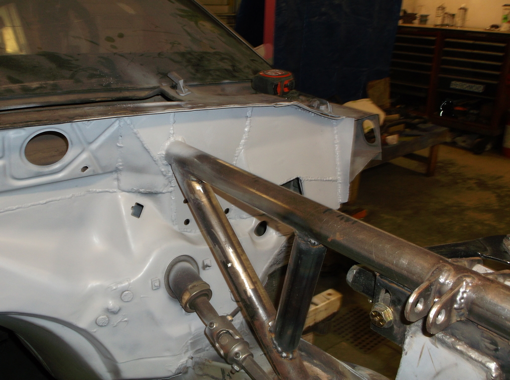
I set up the pass side like I did the drivers with a short piece of 1 5/8 tubing to get the spindle and a-arm in position.
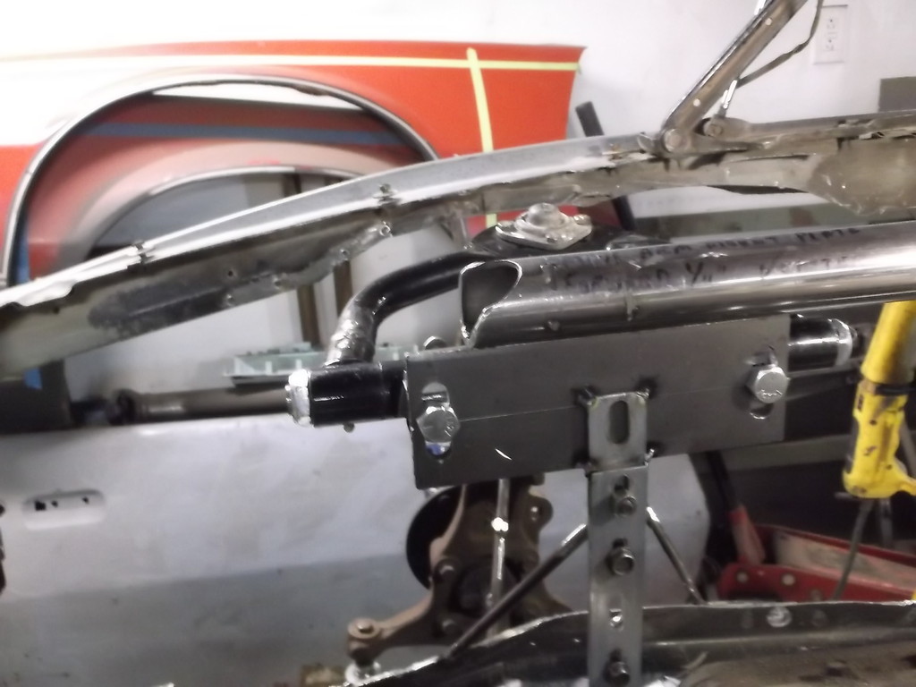
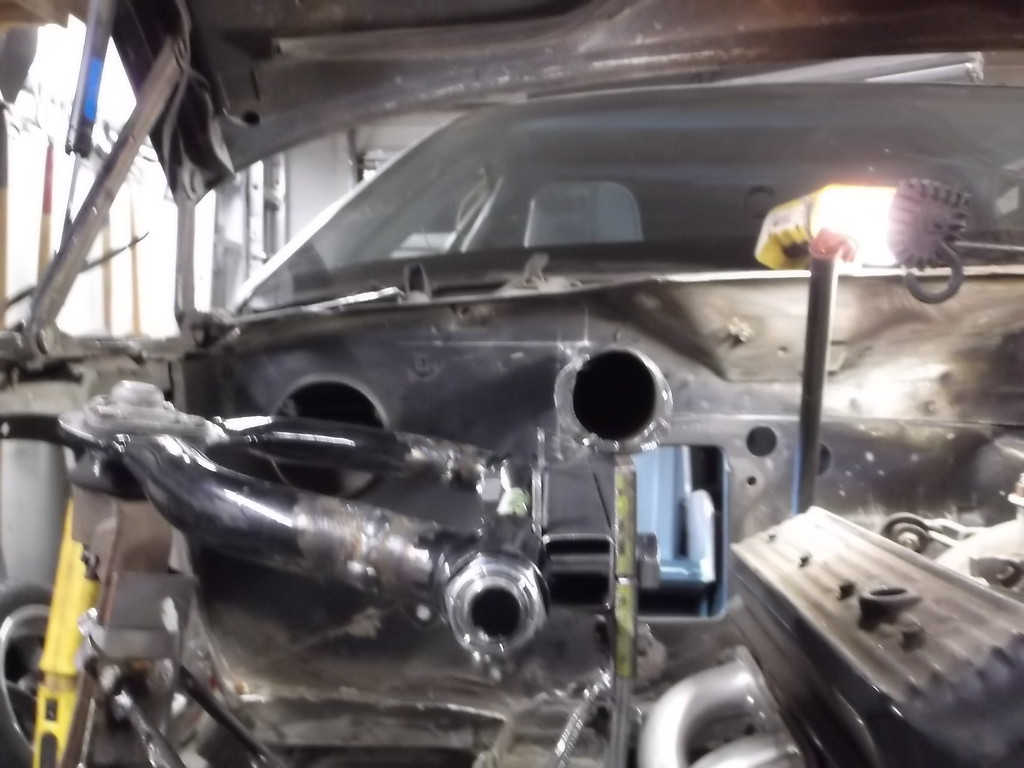
Cut holes in fire wall for tube to pass through. This is pic of tube passing through inside the cowl.
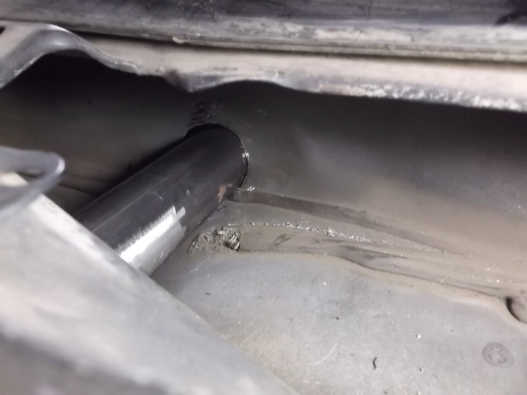
And lining up inside with knee bar.
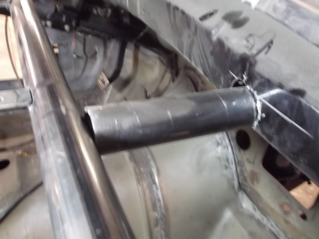
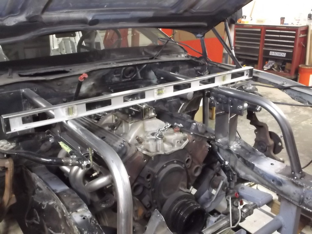
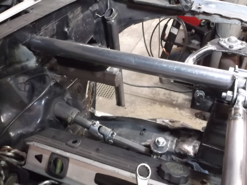
I felt good that the top rails came out perfectly level and parallel with each other.
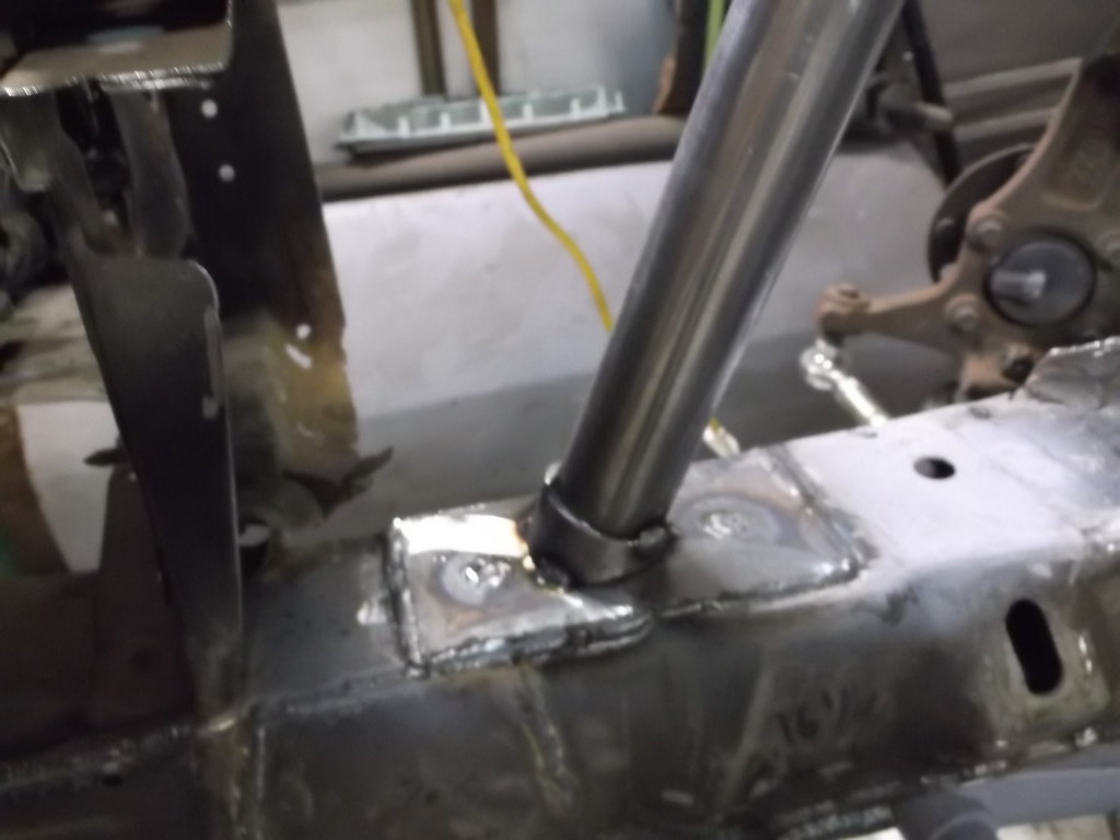
I also used the same method to mount the front of the tube to the lower frame rail.
Here is what i got done.
I set up the pass side like I did the drivers with a short piece of 1 5/8 tubing to get the spindle and a-arm in position.


Cut holes in fire wall for tube to pass through. This is pic of tube passing through inside the cowl.

And lining up inside with knee bar.

I felt good that the top rails came out perfectly level and parallel with each other.

I also used the same method to mount the front of the tube to the lower frame rail.

Thread Starter
Senior Member
Joined: Aug 2007
Posts: 682
Likes: 45
Re: Home brew road racer
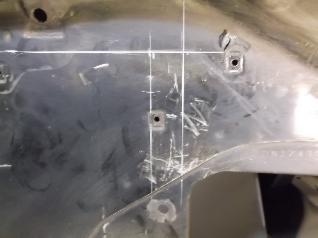
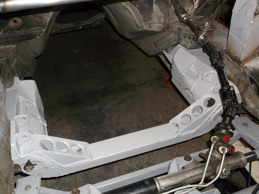
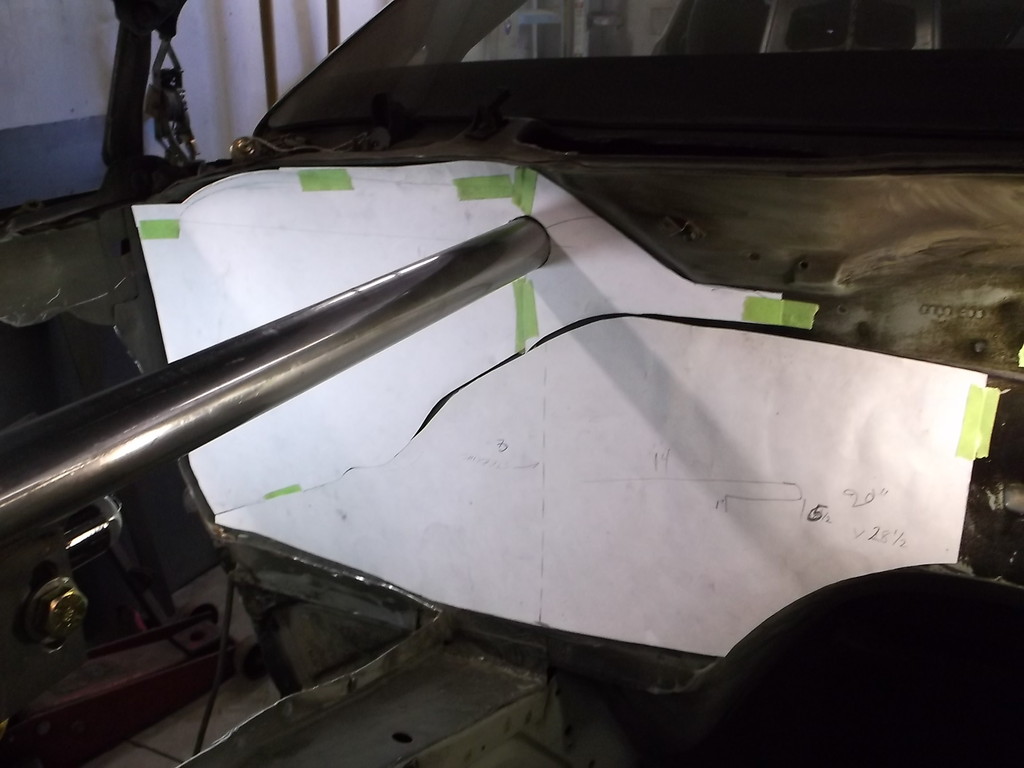
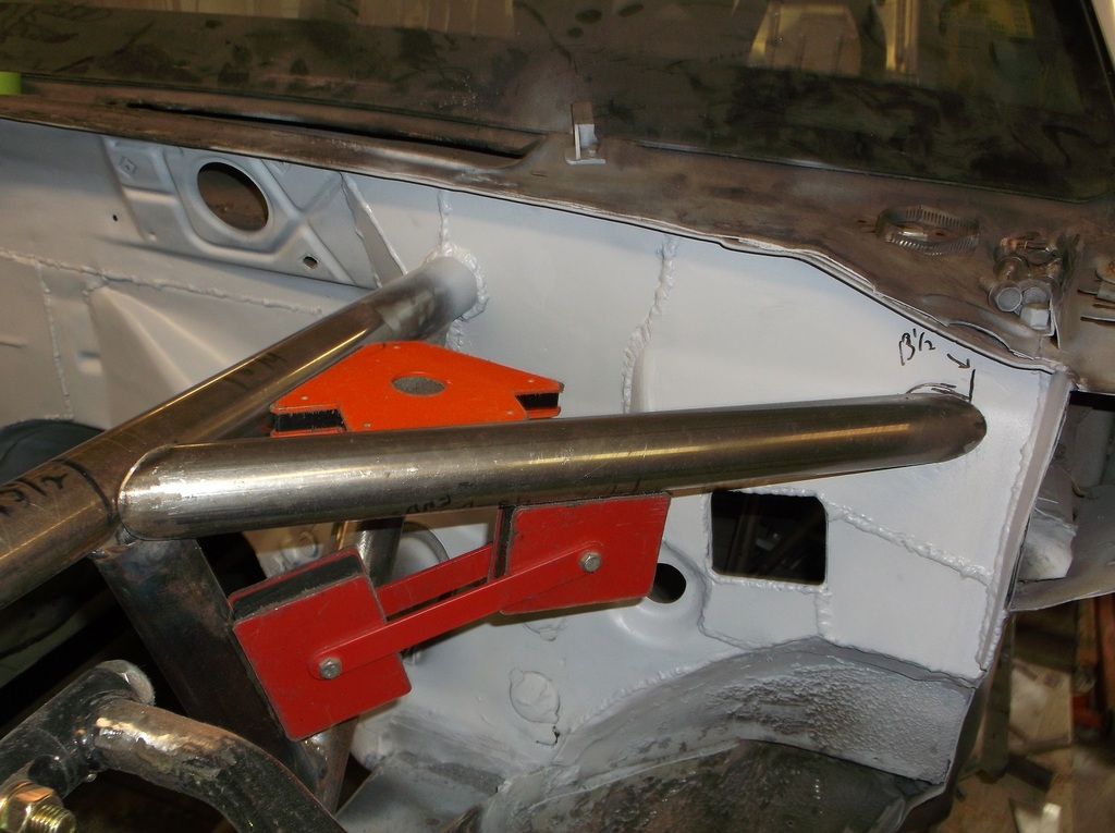
There is no symmetry on this car what soever. The right tube had to be positioned an inch farther in as measured from the outer corner of the firewall than the left side was. Because of that, the template I had made for the shock mounts had to be lengthened an inch also.
Vertical line on right is 15" from edge of firewall. The one on the left puts the tube, a-arm and spindle in the correct position.
 .
.
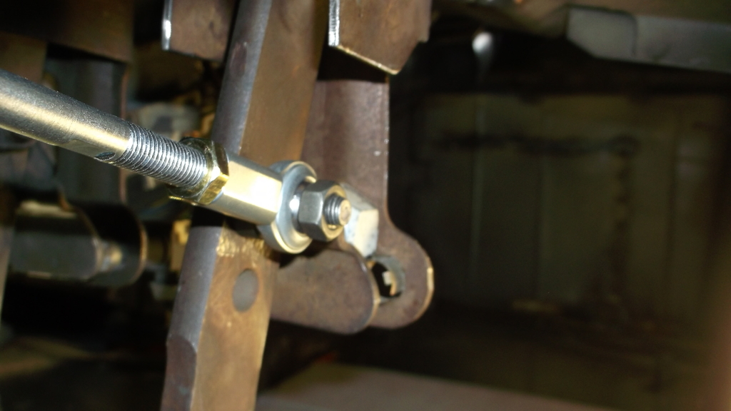
With both shocks properly located I set about linking the two upper mounts together with a lateral brace similar to a strut tower brace.
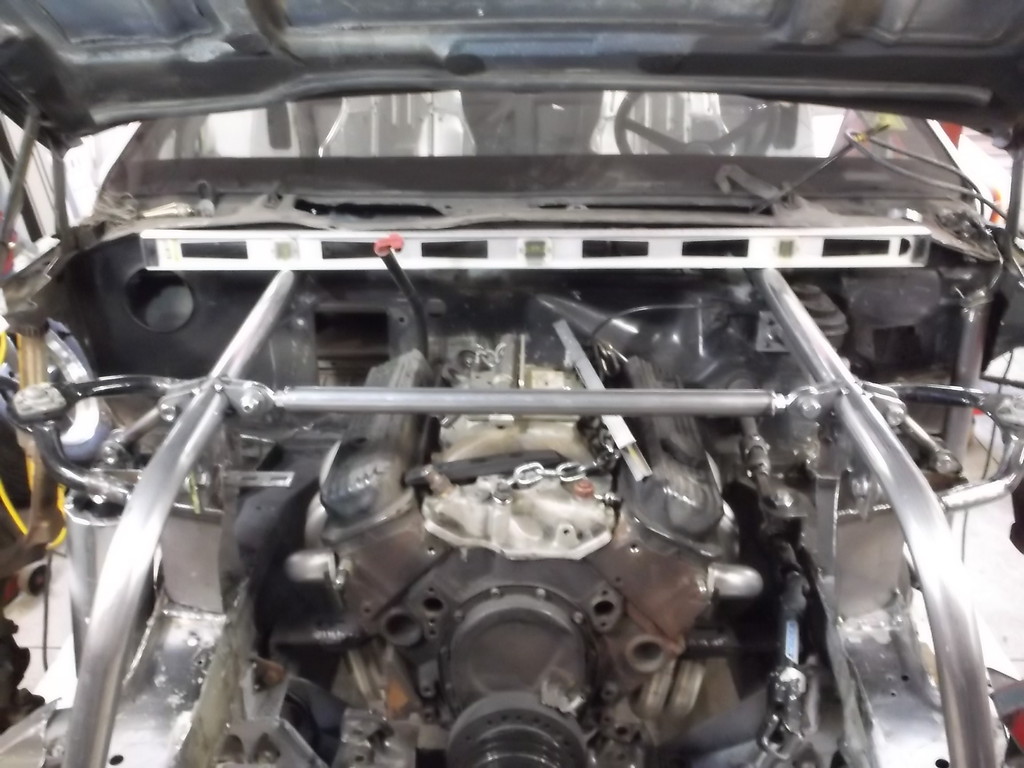
The lateral brace is 1 1/4 x .120 wall tubing with 5/8 threaded inserts welded into the ends. QA1 rod ends with 1/2 hole (same as my inner tie rod ends) let me add some preload to the frame rails.
Vertical line on right is 15" from edge of firewall. The one on the left puts the tube, a-arm and spindle in the correct position.

 .
.With both shocks properly located I set about linking the two upper mounts together with a lateral brace similar to a strut tower brace.


The lateral brace is 1 1/4 x .120 wall tubing with 5/8 threaded inserts welded into the ends. QA1 rod ends with 1/2 hole (same as my inner tie rod ends) let me add some preload to the frame rails.


Thread Starter
Senior Member
Joined: Aug 2007
Posts: 682
Likes: 45
Re: Home brew road racer
Besides the lateral bracing I fully boxed the lower shock mount and painted inside and out to prevent rust. I will still be adding two braces on each side running running around the engine side of the tube and extending to the bottom of the plate that mounts the upper control arm. These will be positioned as close to the a-arm mounting bolts as possible. I am hoping with all of that it will prevent any flex in the front of the chassis.


Once it is all welded in I think I will test it for torsional strength as shown in the book "Chassis Engineering" by Herb Adams.
Thread Starter
Senior Member
Joined: Aug 2007
Posts: 682
Likes: 45
Re: Home brew road racer
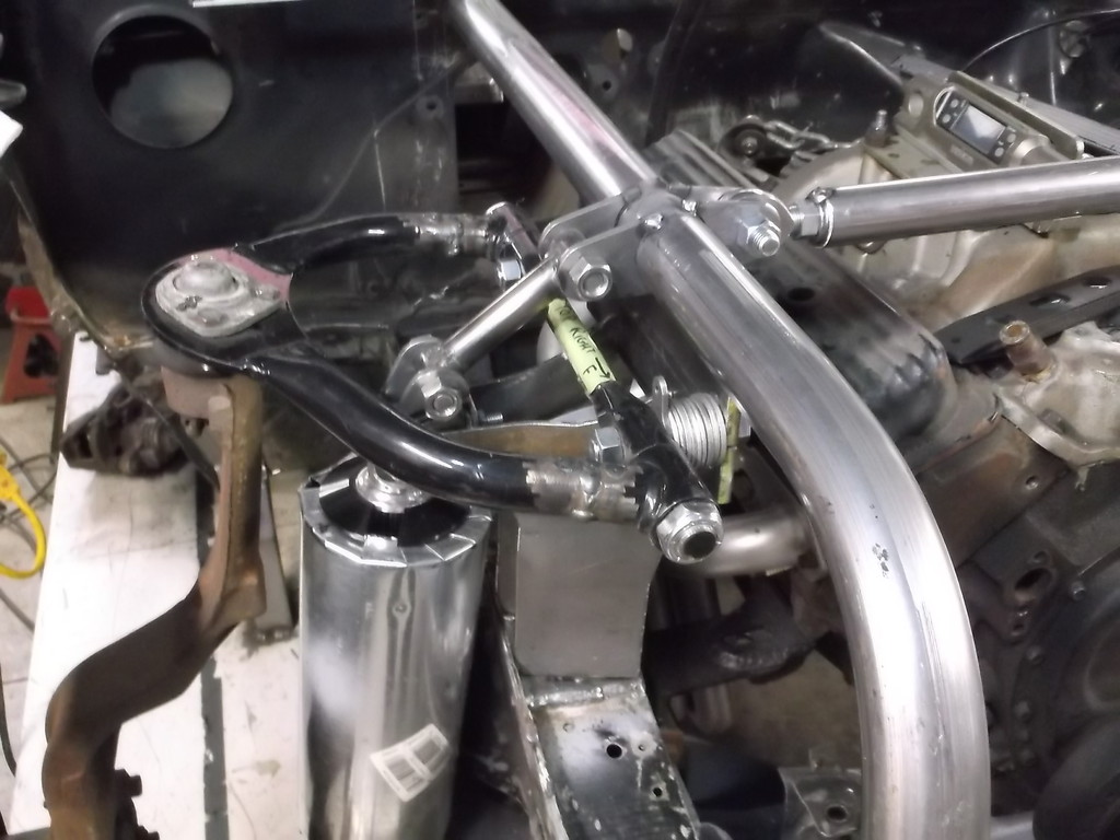
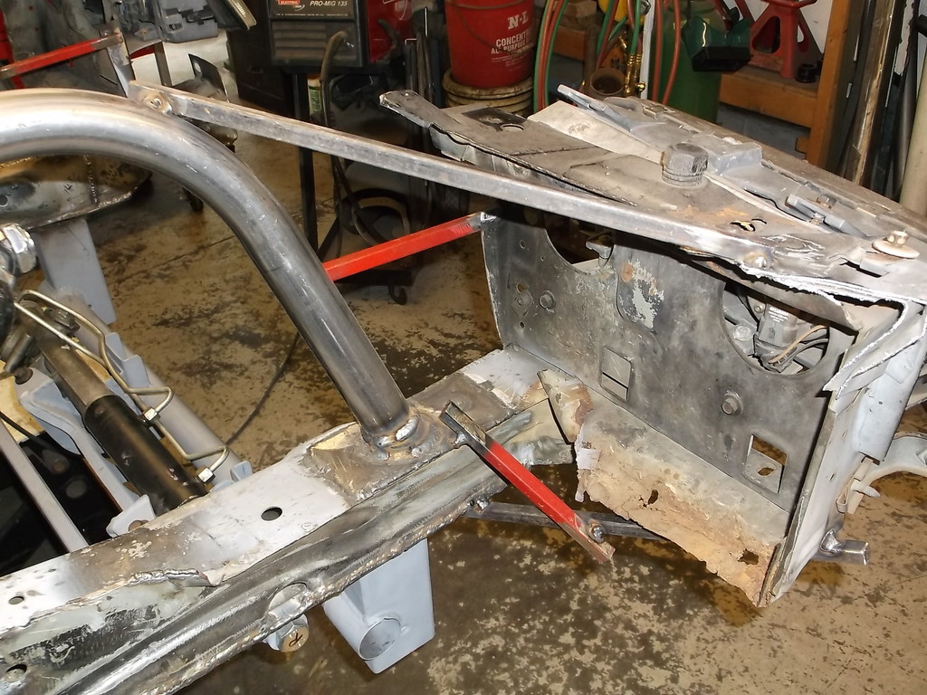
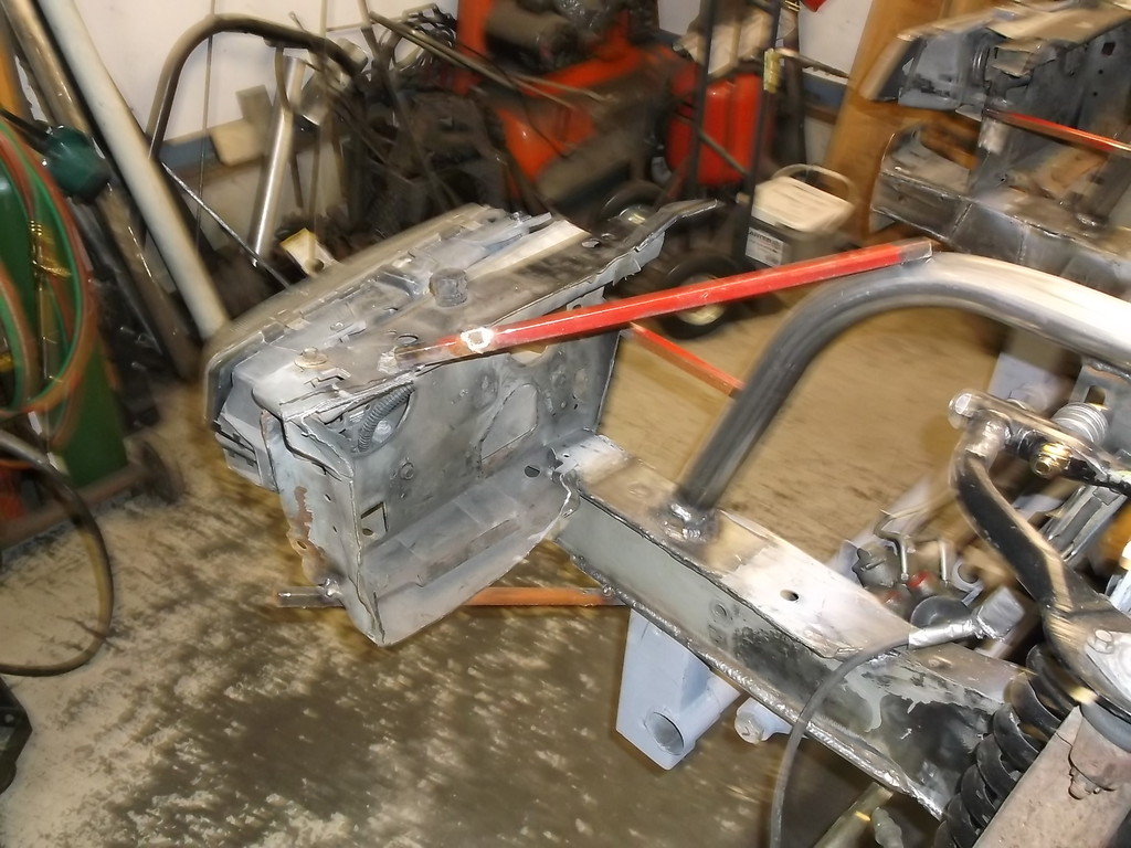
I think I still need to triangulate between the upper and lower frame rails in the space behind the a-arms. See pic.
I can't decide which way would be better between these two pics. (outline is for 1 5/8 tubing)
Two short tubes

Or one long tube
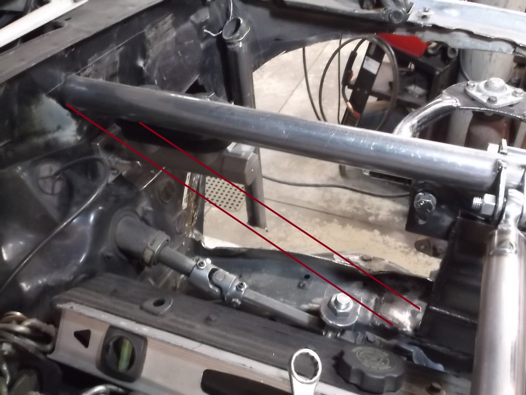

I can't decide which way would be better between these two pics. (outline is for 1 5/8 tubing)
Two short tubes

Or one long tube

Thread Starter
Senior Member
Joined: Aug 2007
Posts: 682
Likes: 45
Re: Home brew road racer
Nothing really new to post. I have pulled the engine and trans out and started to fully weld up all of the brackets and tubes that have just been tack welded in place. Once that is done I can install the coil over shocks with the 400lb springs on them and be able to take the car off the ramps for the first time in 4 years. Cant wait to see it back on the ground!
If I put the engine and trans back in I will be able to get some idea of actual ride height even though I won't have all of the front end pieces back on the car. I could add 150lbs or so of ballast ahead of the motor and rescale the car to see if I actually improved the weight distribution by moving the front wheels forward 5 inches.
While doing all this work on the front end and working with the 4th gen spindles and such I really think they could be adapted to a stock 3rd gen k-member and lower control arms without a lot of modifications. The 3rd and 4th gen lower ball joint are the same so it would be a direct bolt in there. You would keep the 3rd gen coil springs. Keeping the 3rd gen coil springs it would keep the force of the spring on the frame and not on the wheel well.
The only mounting issue would be the upper control arm and shock mount. If the car is not severely lowered like mine (4 inches lower than stock height) there shouldn't be a problem keeping it under the stock wheel well. A reinforcement/mounting plate made from 3/16 or 1/4 plate with slots for caster/camber should be all that is needed. Up travel of the control arm would have to be considered so the mount will probably need to be located a few inches below the top of the wheel well. Mounted to a 26 inch tall tire the top of the spindle is about 28 inches high. If somebody would want to get the height of the inner wheel well on a near stock height 3rd gen I could make a pretty good assumption if this would work.
Thread Starter
Senior Member
Joined: Aug 2007
Posts: 682
Likes: 45
Re: Home brew road racer
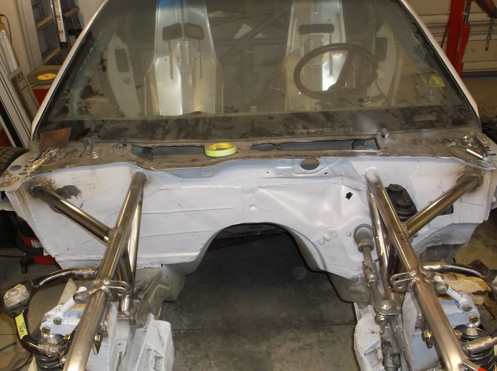
WE HAVE SUSPENSION!!!!!!!!!!!!!!
I got all the brackets welded up so we could mount the coil overs and springs. The coil overs that I bought recommended a 14" long spring but the distance between the spring seats is only 12". Trying to compress a 400lb/in spring safely is a bit of a challenge. I modified one of those harbour freight hydraulic pipe crushers, umm I mean pipe benders. I think many of us here have one or tried one. I'll post picks if anyone wants to see it. Not pretty but I was able to mount the coil over shock in the press, drop the spring over it, bolt on a top plate and push the shock up through the spring until I could slip the top retaining collar onto the shock shaft and then release the ram and wallah, coil spring on shock.
Not perfect because it scraped some of the black powdercoat off a couple coils but at least I didn't have to handle a banded spring.
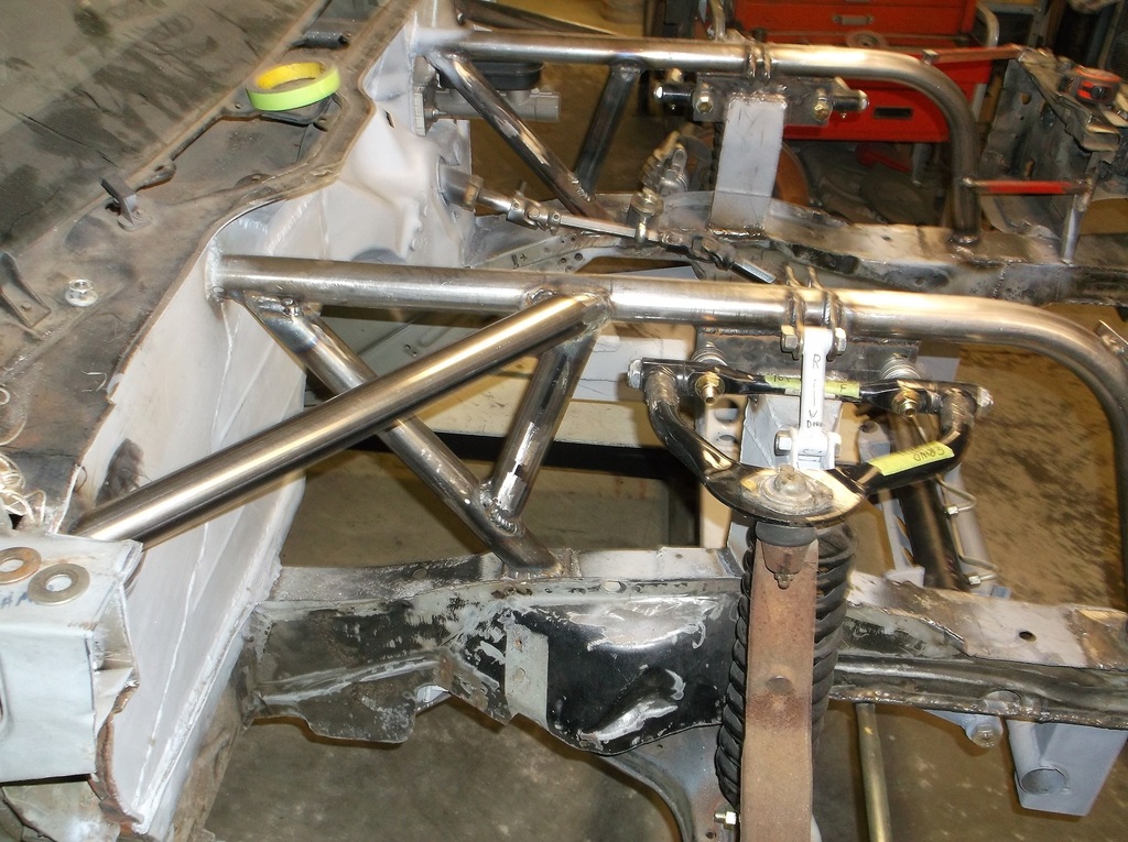
Here is the completed suspension.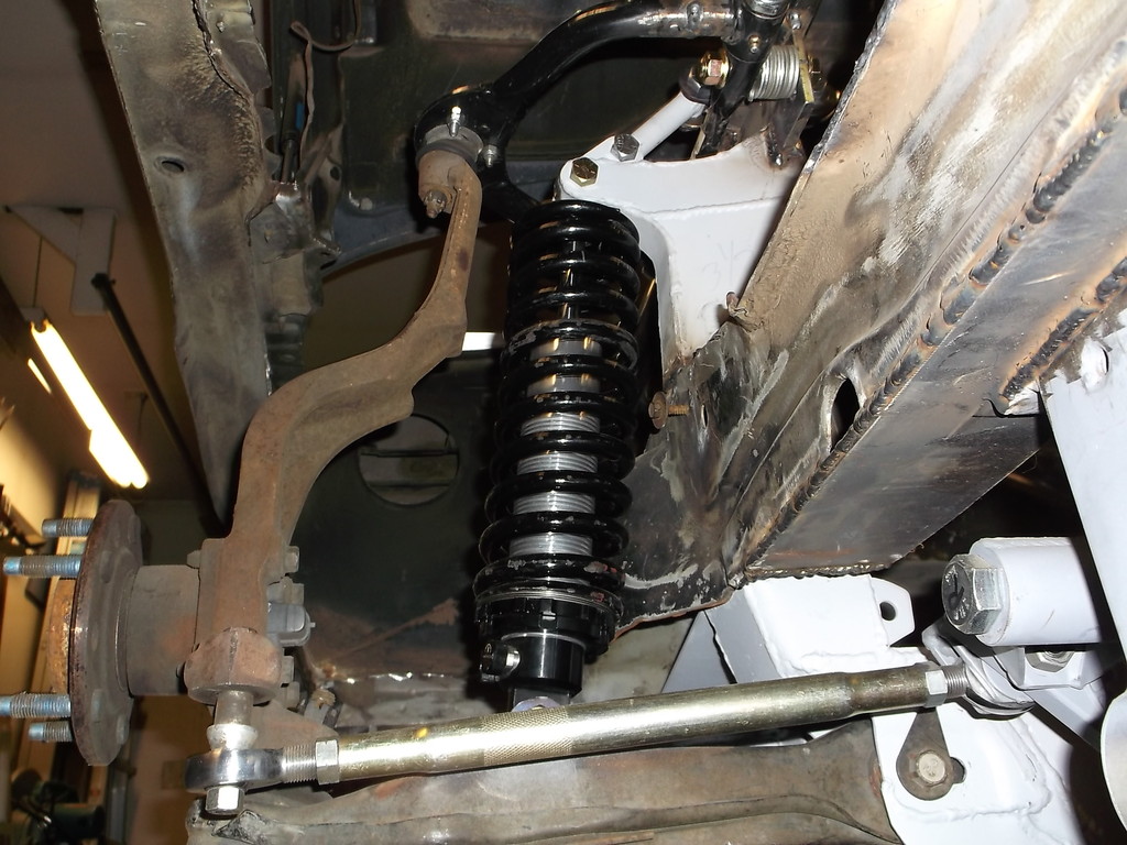
I have not yet orderd the Spohn bump steer kit or the splined sway bar. I should have these in the next couple weeks.
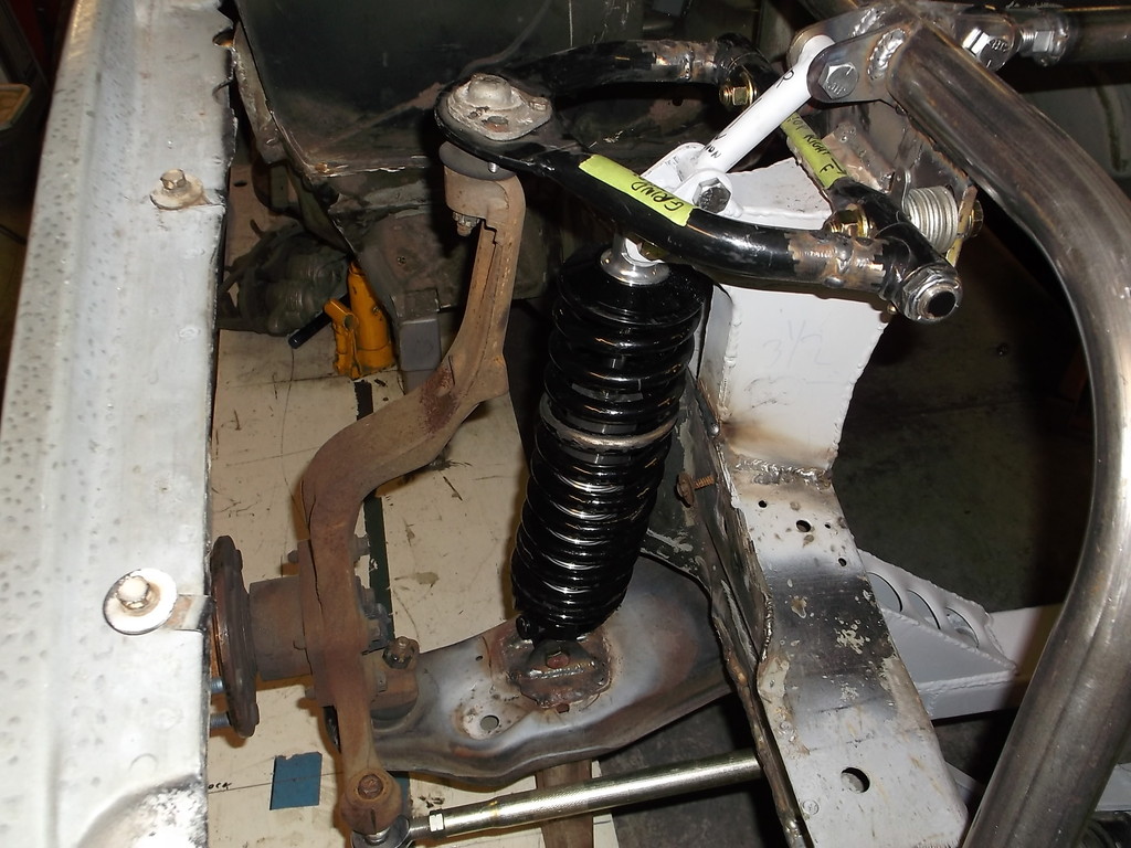
The cross brace between the top rails is really needed as there is a tremendous amount of force pushing in on the rails. I will also be adding the diagonal bracing from the top rail to the outer ends of the firewall as I showed in earlier posts. I am pretty sure that the 400lb springs will be too much. I have no adjustment left to lower the car if it sits too high. If I end up with 350lb or even 325lb springs I will probably get 12" long as I would have plenty of thread left for adjustments.
I got all the brackets welded up so we could mount the coil overs and springs. The coil overs that I bought recommended a 14" long spring but the distance between the spring seats is only 12". Trying to compress a 400lb/in spring safely is a bit of a challenge. I modified one of those harbour freight hydraulic pipe crushers, umm I mean pipe benders. I think many of us here have one or tried one. I'll post picks if anyone wants to see it. Not pretty but I was able to mount the coil over shock in the press, drop the spring over it, bolt on a top plate and push the shock up through the spring until I could slip the top retaining collar onto the shock shaft and then release the ram and wallah, coil spring on shock.
Not perfect because it scraped some of the black powdercoat off a couple coils but at least I didn't have to handle a banded spring.
Here is the completed suspension.


I have not yet orderd the Spohn bump steer kit or the splined sway bar. I should have these in the next couple weeks.

The cross brace between the top rails is really needed as there is a tremendous amount of force pushing in on the rails. I will also be adding the diagonal bracing from the top rail to the outer ends of the firewall as I showed in earlier posts. I am pretty sure that the 400lb springs will be too much. I have no adjustment left to lower the car if it sits too high. If I end up with 350lb or even 325lb springs I will probably get 12" long as I would have plenty of thread left for adjustments.
Thread Starter
Senior Member
Joined: Aug 2007
Posts: 682
Likes: 45
Re: Home brew road racer
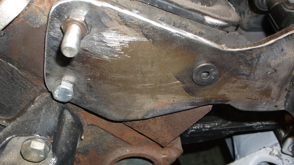
i removed the k-member and finished welding the remaining braces. I set it on a couple of the wheel scales and it weighs 45lbs, on par with the stock k-member. It is very strong. Tightening any one of the 6 mounting bolts will pull the entire k-member tight to the frame.
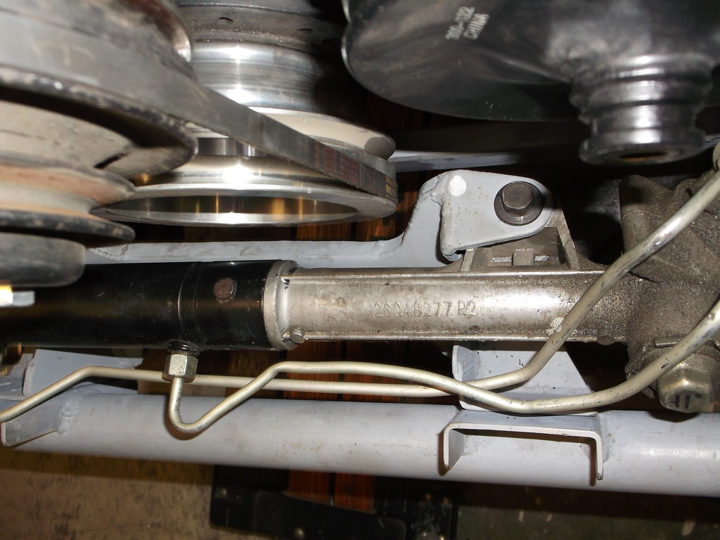
While I had the scales out I removed the rack and pinion assembly and weighed it. With all the modifications it weighs 30lbs, a little less than the stock gearbox.
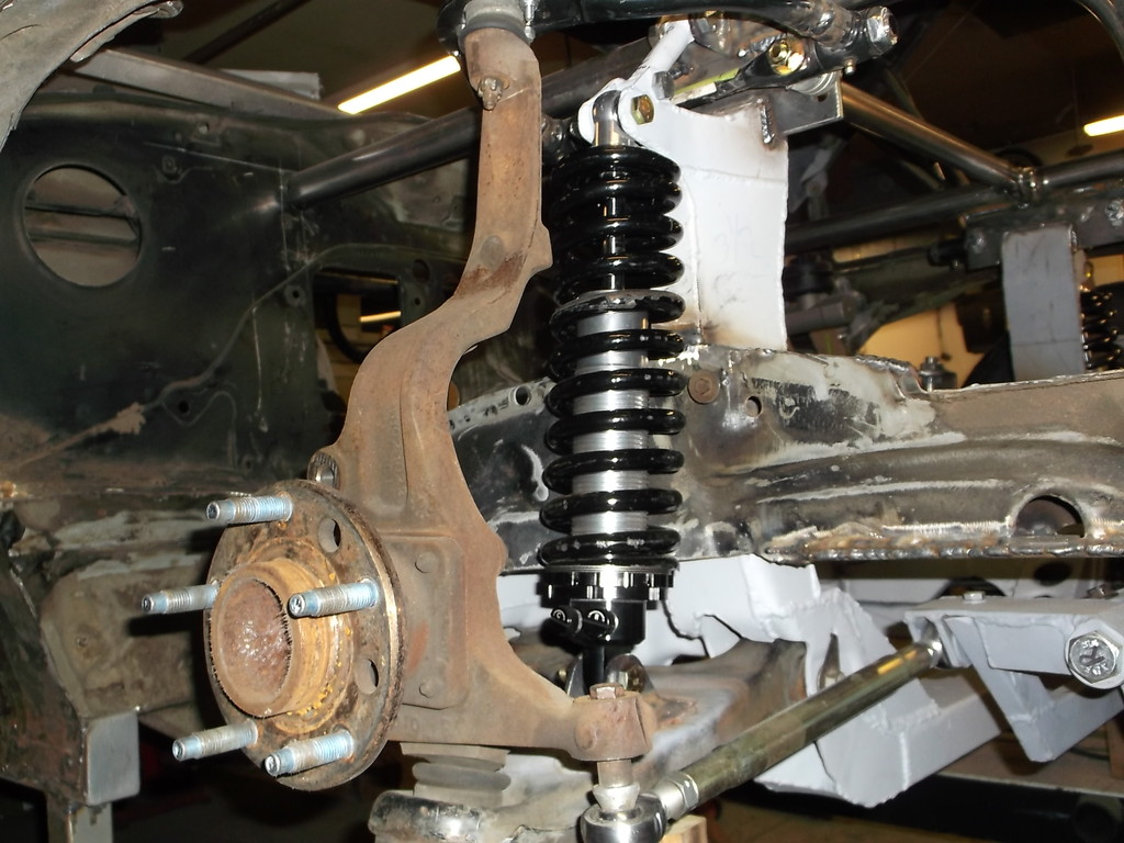
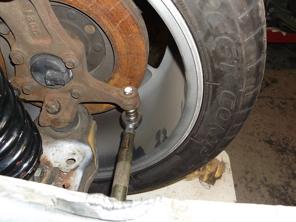
A few pics with the brakes and wheel installed at ride height.
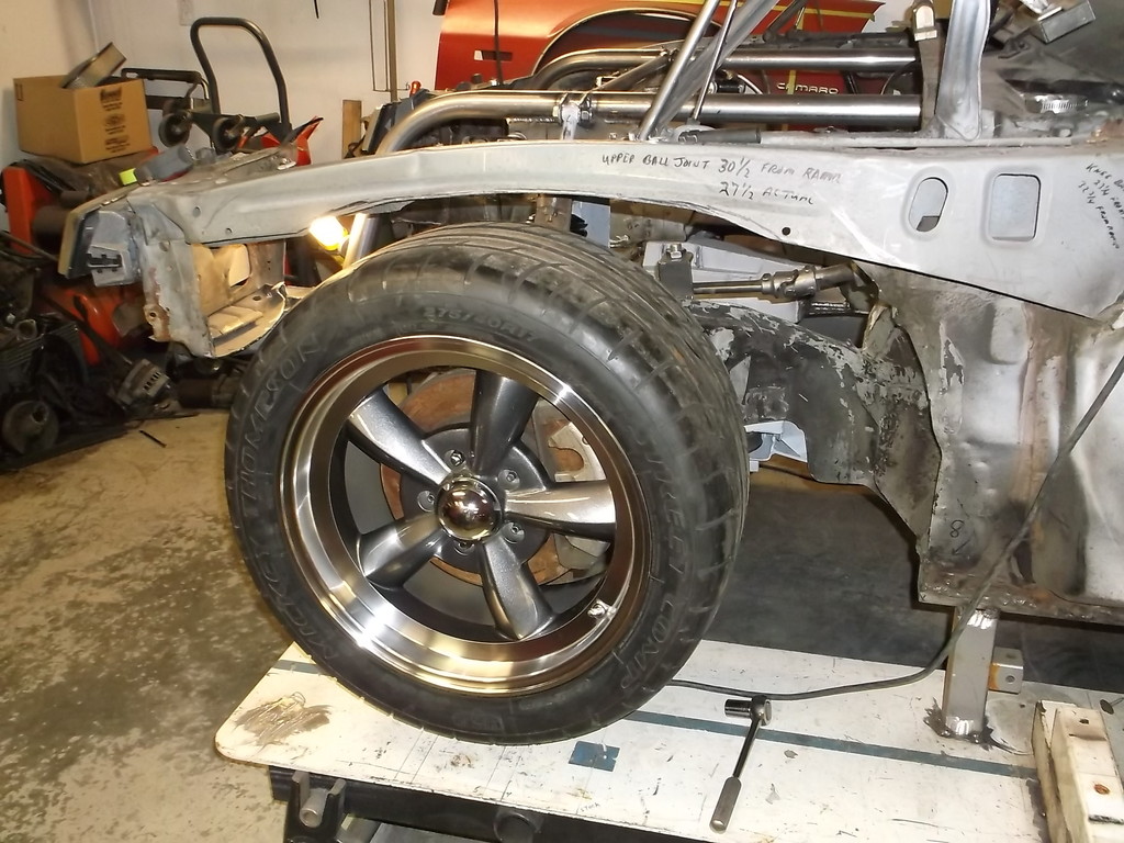
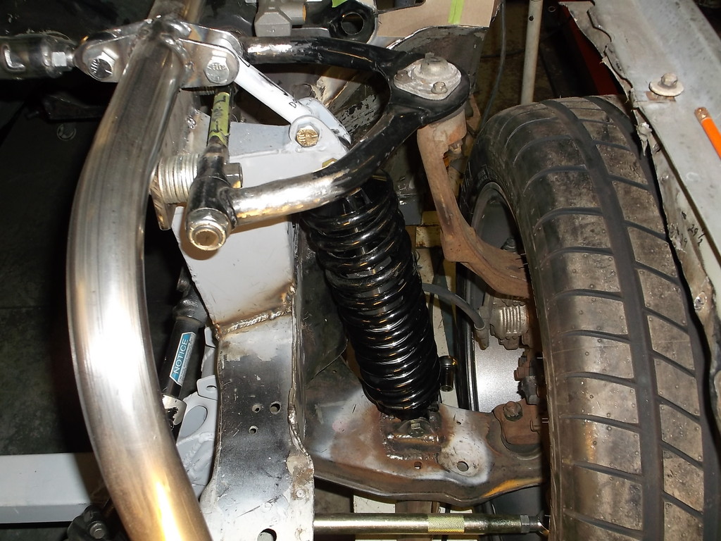
The wheel is 17x9 with 6" back space. I could easily go 17x11 or 18x11 with 8" back spacing and run 315's on all 4 corners.
because the 4th gen spindle has a much shorter steering arm there is no interference issues and plenty of room for the bump steer kit.


While I had the scales out I removed the rack and pinion assembly and weighed it. With all the modifications it weighs 30lbs, a little less than the stock gearbox.
A few pics with the brakes and wheel installed at ride height.


The wheel is 17x9 with 6" back space. I could easily go 17x11 or 18x11 with 8" back spacing and run 315's on all 4 corners.
because the 4th gen spindle has a much shorter steering arm there is no interference issues and plenty of room for the bump steer kit.

Thread Starter
Senior Member
Joined: Aug 2007
Posts: 682
Likes: 45
Re: Home brew road racer
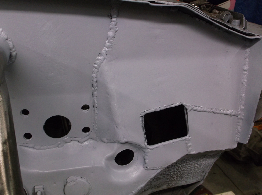
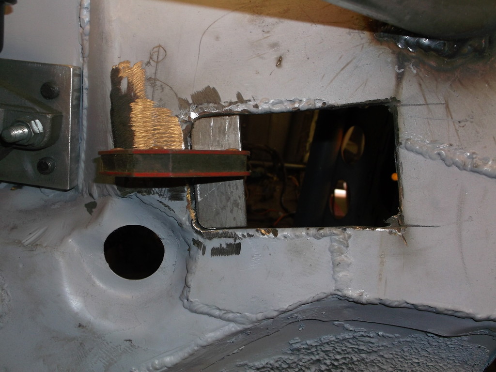
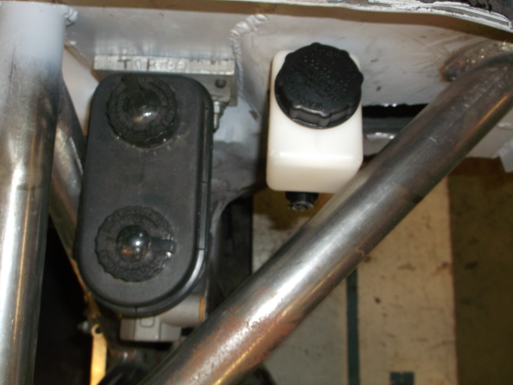
With all the welding going on there is a lot of cool down time. I used the time to plan out some of the firewall reinforcements. I plan on mounting the hydraulic clutch master cylinder in the space between the brake master cylinder and the square opening for the engine wire harness.
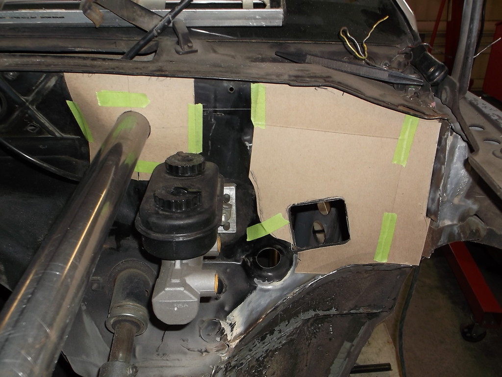
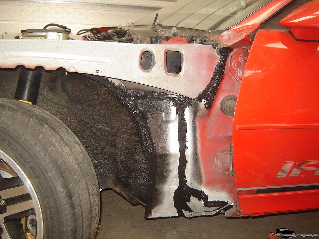
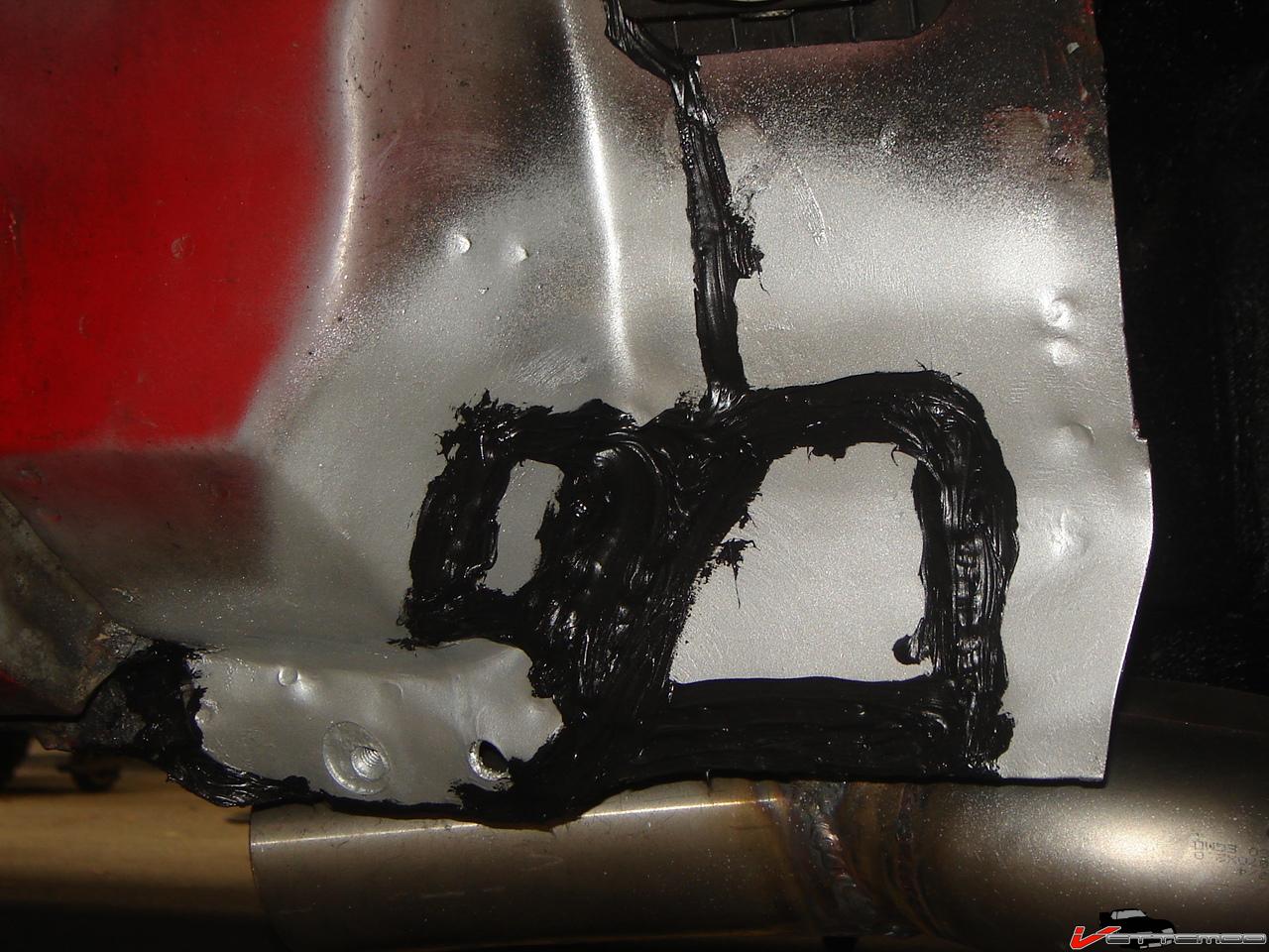
This corner is covered with large gobs of seam sealer from the factory. While cleaning it away I discovered that all the lower spot welds were missing and the seam sealer was pumped in between the this corner brace and the fender brace. I plan on plating this area also to give a little extra structure to the firewall where I will be mounting the diagonal brace for the top frame rail.


This corner is covered with large gobs of seam sealer from the factory. While cleaning it away I discovered that all the lower spot welds were missing and the seam sealer was pumped in between the this corner brace and the fender brace. I plan on plating this area also to give a little extra structure to the firewall where I will be mounting the diagonal brace for the top frame rail.

Thread Starter
Senior Member
Joined: Aug 2007
Posts: 682
Likes: 45
Re: Home brew road racer
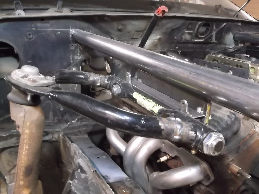
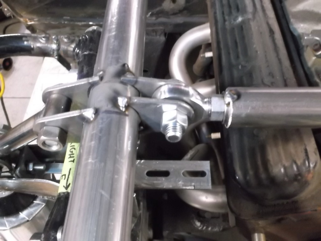
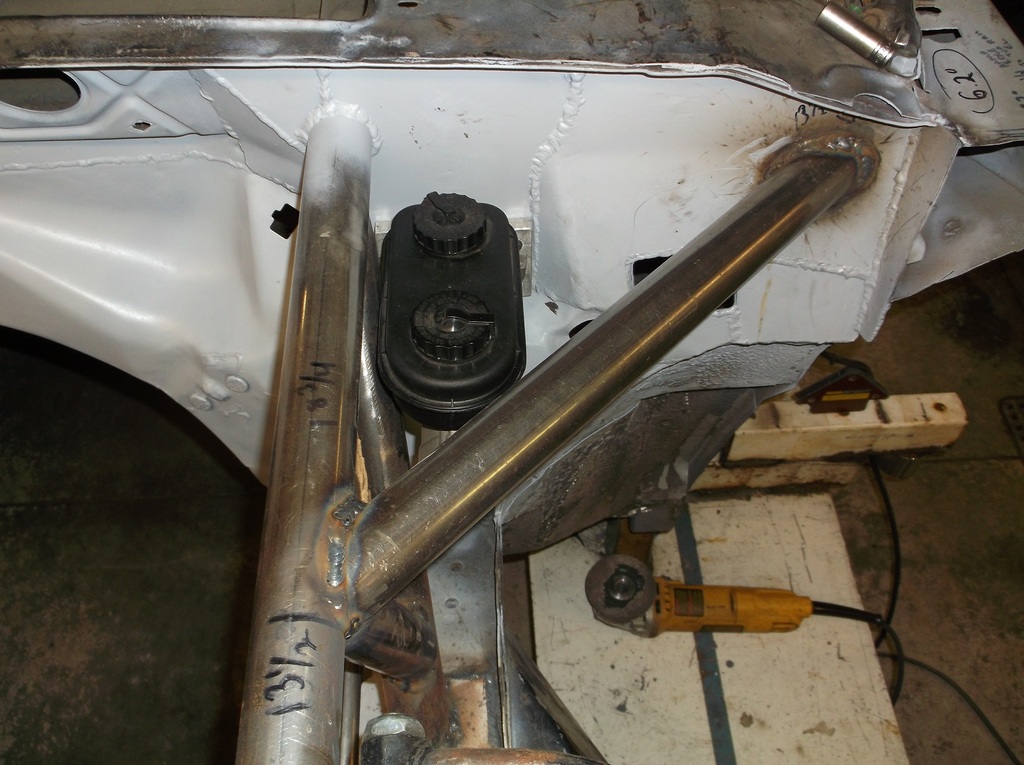
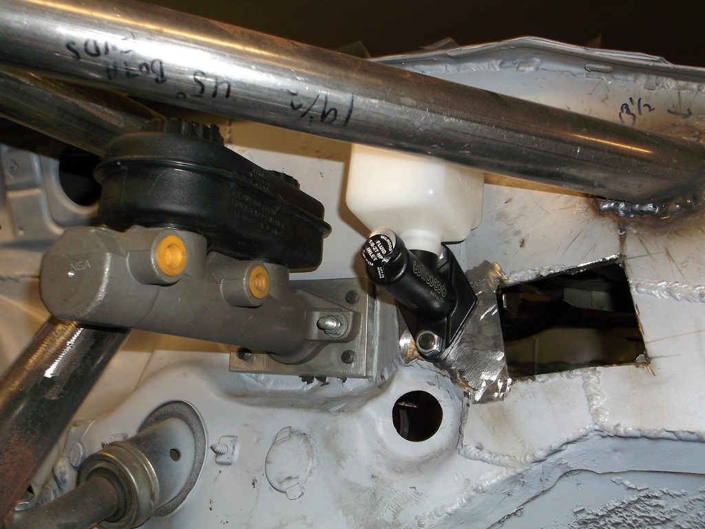
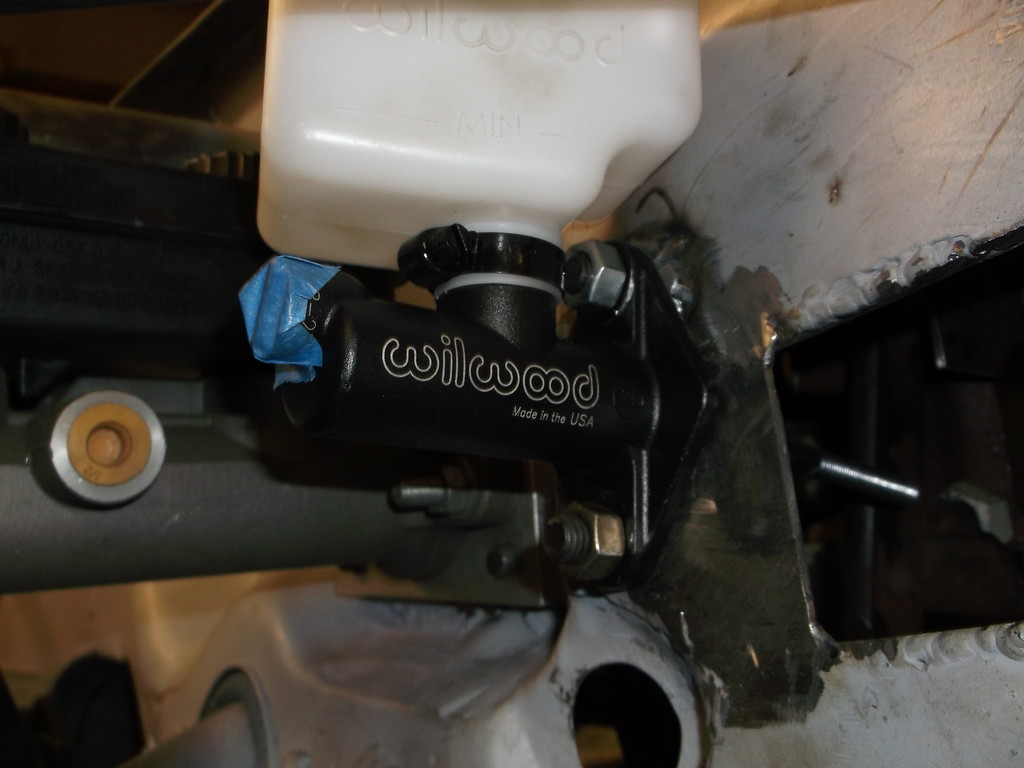
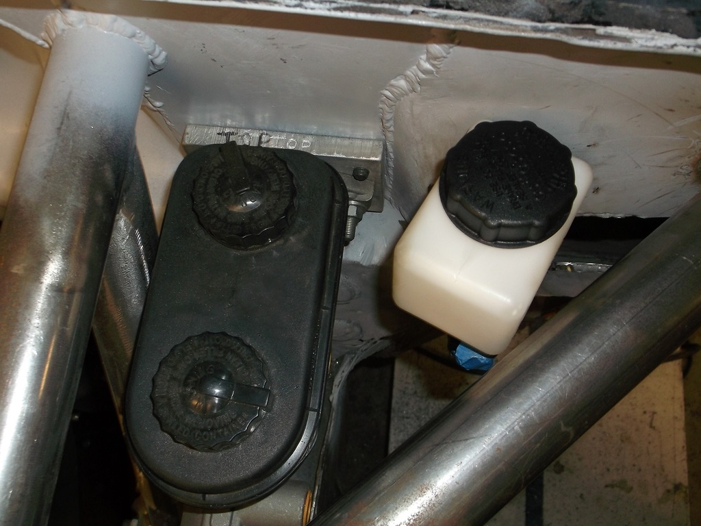
A little more done over the last few days.
There is about 1/8" clearance between bar and reservoir.
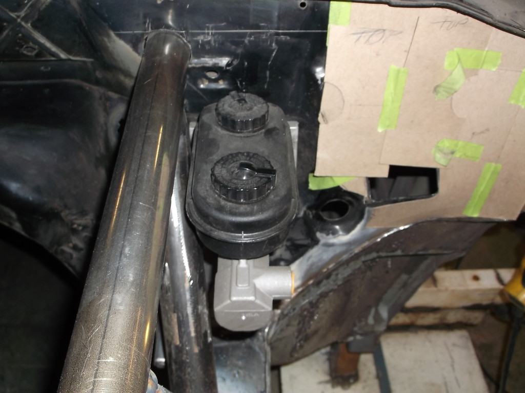
Once I get the firewall reinforced I will add the diagonal brace.
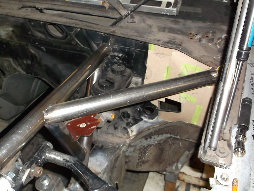
I think I have enough bracing now to prevent any flex in the front framework. This should let the suspension parts work to their optimum and make any chassis adjustments noticeable.

There is about 1/8" clearance between bar and reservoir.

Once I get the firewall reinforced I will add the diagonal brace.


I think I have enough bracing now to prevent any flex in the front framework. This should let the suspension parts work to their optimum and make any chassis adjustments noticeable.
Thread Starter
Senior Member
Joined: Aug 2007
Posts: 682
Likes: 45
Re: Home brew road racer
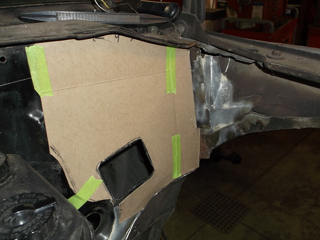
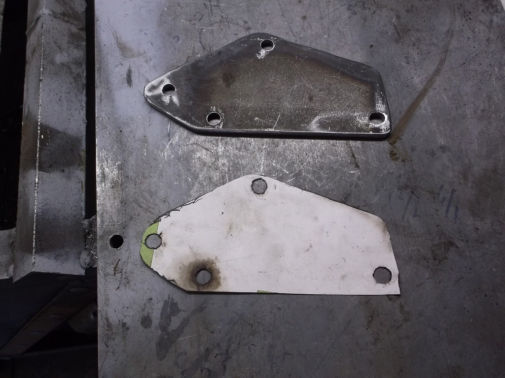
The passenger side will get the same bracing as the left. Reinforcing the firewall and the placement of the diagonal brace requires eliminating the stock blower motor and housing. I will smooth the firewall on the passenger side. To get maximum strength for the diagonal brace and the the top tube rail I will make a plate that will span the distance between them plus a little more. This will be 1/8" sheet steel and follow the factory seam. Below the seam I will use 18g sheet steel to cover all of the remaining heater and heater hose openings.
The templates look something like this.
The templates look something like this.

Member
Joined: Aug 2009
Posts: 332
Likes: 0
From: this car
Car: 85 Z28
Engine: 93 LT1
Transmission: Auto
Axle/Gears: 3.73 01 SS
Re: Home brew road racer
That's got to be one of the most in depth front end suspension type deals I've ever seen. I don't know if you posted this before, forgive me if you did, but what are you aiming for as far as final ride height goes vs stock height?

Member


Joined: Jun 2013
Posts: 497
Likes: 4
From: El Sobrante, California
Car: 1984 z28
Engine: Crate replacement L31R 350
Transmission: T56
Axle/Gears: 7.625" 28 spline 3.23
Re: Home brew road racer
Man. Most track cars that I know of have kissed the wall at one point.
I hope you wont have many issues straightening out a fairly minor hit.
Take and record many measurements.
I hope you wont have many issues straightening out a fairly minor hit.
Take and record many measurements.
Thread Starter
Senior Member
Joined: Aug 2007
Posts: 682
Likes: 45
Re: Home brew road racer
Catman, basiccamaro and ramlt, thanks for following along. I hope the build has been as interesting to follow as it has been in building it. Anyway to answer your questions...
Catman the ride height at the front edge of the subframe connectors is set to be 5 inches. The car originally was 9 inches to the bottom of the rocker pinch weld. I have posted a lot of pictures to get as many eyes on this as possible in hopes that someone might see something wrong or unsafe and bring it to my attention. As far as I know no one on TGO has done this before so I am in uncharted waters.
Basiccamaro, The location of the upper arm was determined by the front roll center height. I wanted to keep it between 2 and 4 inches above the ground and with the upper arm set in the middle of the adjusting slot I should be close to the 2" roll center. The lower the upper arm pivot is located, the higher the roll center.
Camber gain is the result of the short upper a-arm and the longer lower a-arm swinging through two different arcs. The shorter the upper arm gets the smaller its arc and the more camber gain you get. Dropping the pivot point as you suggested would give me a little more camber gain as the ball joint would be farther along in the arc.
In an earlier post, before the shocks were mounted, I ran the suspension through its full travel. Starting at ride height with -.5 degree static camber the wheel gained a little over 1.5 degrees of negative camber through 3 inches of compression. This camber gain stayed pretty consistent whether I started with -.5*, -1.5*, or -2.5* static camber. Again the camber gain is a function of the difference in a-arm length.
Ramlt, fixing crash damage is not something I look forward to but is something any of us who plan on racing a car at high speeds ie road racing or even drag racing, have to think about. For mostly stock style cars the dimensions to check for frame twist or bend can be found in body repair manuals and on the web. For custom jobs like mine I will have to keep a log book with diagrams of the chassis measurements, suspension mounting locations etc. Hopefully all the extra bracing will help it survive an off track incident. I also have a notebook that list the all the parts I have used on the car to date. That way when I need a replacement heim for the rear 3 link I can just get the QA1 part number from the log book and order it on line with no guess work.
Thread Starter
Senior Member
Joined: Aug 2007
Posts: 682
Likes: 45
Re: Home brew road racer
Before I could plate the firewall I had to remove the upper OE frame structure where the fenders attached. I wanted to keep the remaining core support behind the headlights so I had to brace that area first.
I left a short stub extending out from the firewall to allow me to make a reinforced corner for a little more rigidity. The end of the stub will get an end plate welded to it.
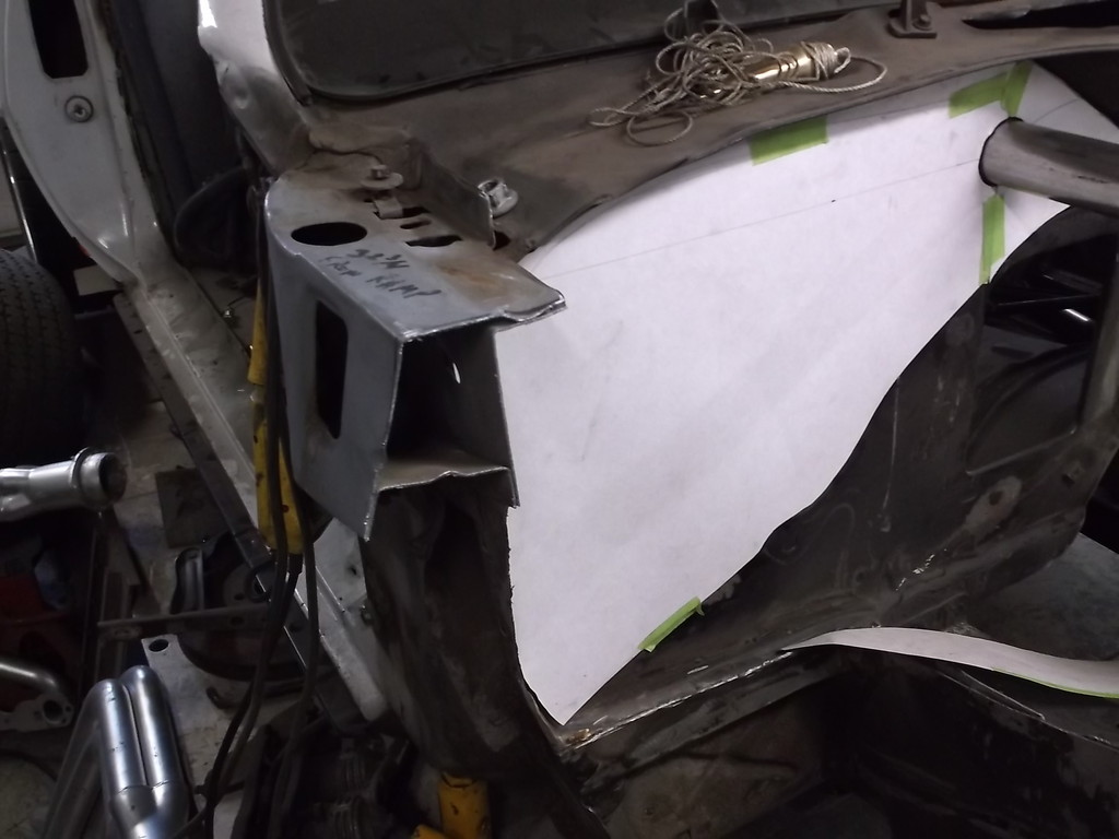
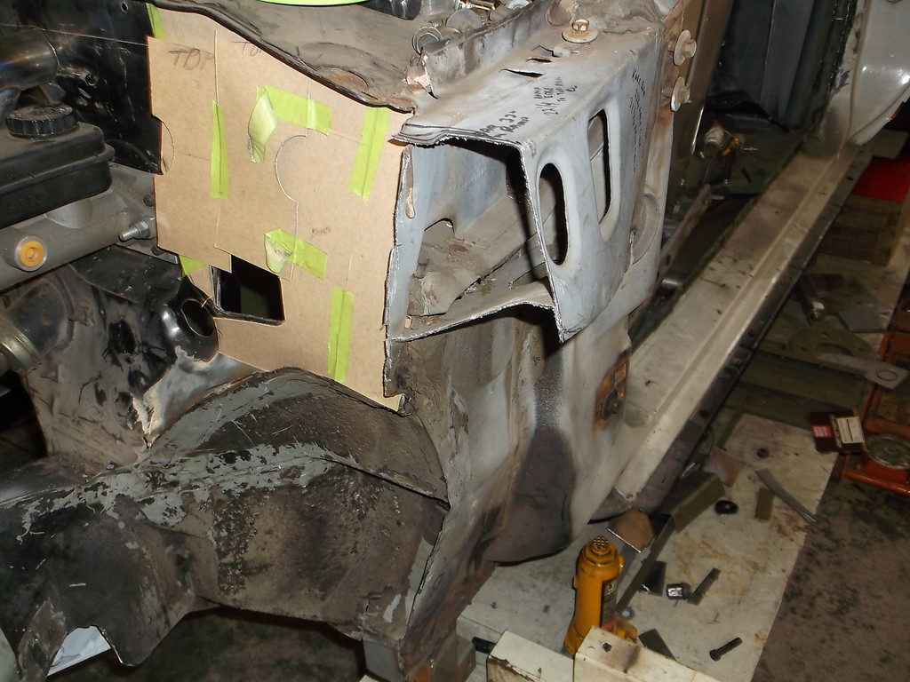
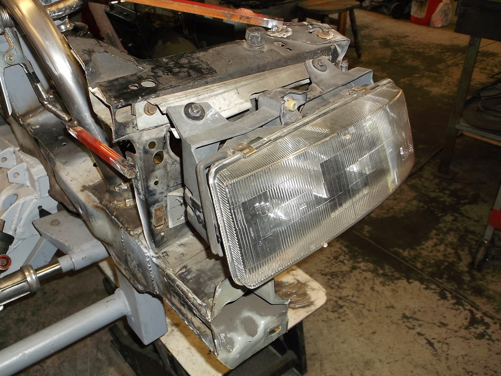
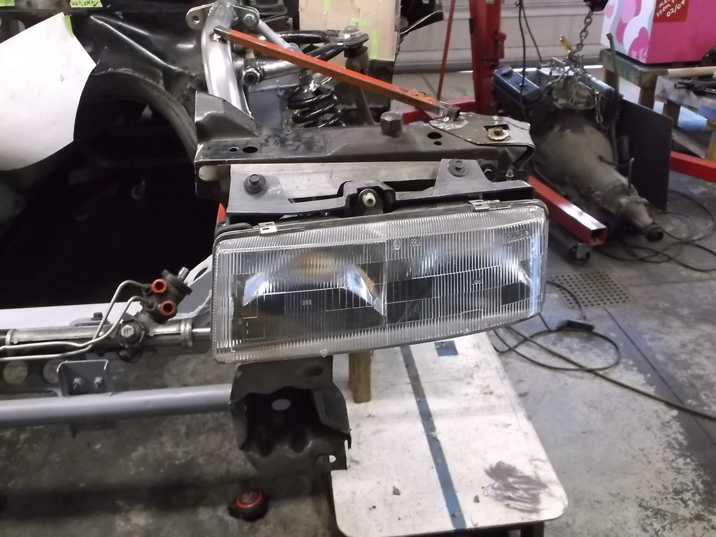
The headlights are from a 90-93 Lumina APV van. They angle back and have a slight curve to them that really blends in with the shape of the factory front end. I like the idea of the headlight assembly mounting to the core support rather than the factory fiberglass structure that mounts the nose, headlights and front edge of the fenders. The slightest impact to the nose or fender and that structure is broken. With the lights mounted to the core support I can remove the nose and not have to touch the headlights.
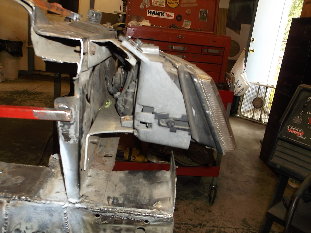
The factory core support that remains behind the headlights will be replaced by a small diameter tubular frame work. I left the factory piece there for now so I would have the front mounting bolt for the front fender.


I left a short stub extending out from the firewall to allow me to make a reinforced corner for a little more rigidity. The end of the stub will get an end plate welded to it.


The headlights are from a 90-93 Lumina APV van. They angle back and have a slight curve to them that really blends in with the shape of the factory front end. I like the idea of the headlight assembly mounting to the core support rather than the factory fiberglass structure that mounts the nose, headlights and front edge of the fenders. The slightest impact to the nose or fender and that structure is broken. With the lights mounted to the core support I can remove the nose and not have to touch the headlights.


The factory core support that remains behind the headlights will be replaced by a small diameter tubular frame work. I left the factory piece there for now so I would have the front mounting bolt for the front fender.
Thread Starter
Senior Member
Joined: Aug 2007
Posts: 682
Likes: 45
Re: Home brew road racer
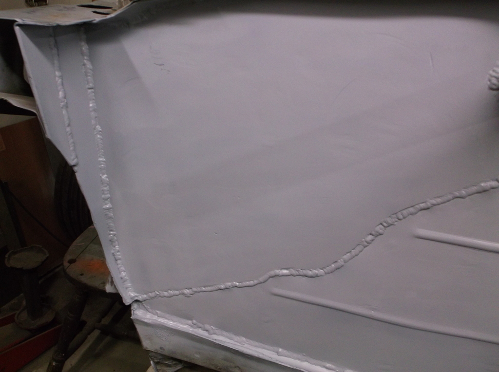
Some pics of the firewall reinforcement. Welding to this is no easy task due to the multiple layers of sheet metal, gaps between the layers and that some of the layers are galvanized or have seam sealer between the layers. A real PITA. If you are just smoothing the firewall and not reinforcing it as I am, I would recommend painting both surfaces and use a panel adhesive to attach the panel covering the factory firewall.
1/8" steel plate flame cut to rough size then trimmed with cutoff wheel.
To keep the plate tight to the oe firewall I drilled several holes through both the plate and firewall and used the factory fender bolts and "J" nuts to draw the pieces together. i also drilled several 3/8 holes to plug weld the plate to the firewall. Before I bolted the pieces together, all mating surfaces were sanded and covered with several coats of rust preventive primer. Immediately before bolting the plate to the firewall I sprayed one last heavy wet coat on the plate in hopes it would eliminate any gaps between the two panels.
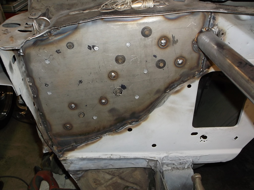
I bounced back and forth from pass side to drivers side making short stitch welds to prevent burn through and minimize warpage. Here is start of reinforcement on driver side.
1/8" steel plate flame cut to rough size then trimmed with cutoff wheel.

To keep the plate tight to the oe firewall I drilled several holes through both the plate and firewall and used the factory fender bolts and "J" nuts to draw the pieces together. i also drilled several 3/8 holes to plug weld the plate to the firewall. Before I bolted the pieces together, all mating surfaces were sanded and covered with several coats of rust preventive primer. Immediately before bolting the plate to the firewall I sprayed one last heavy wet coat on the plate in hopes it would eliminate any gaps between the two panels.

I bounced back and forth from pass side to drivers side making short stitch welds to prevent burn through and minimize warpage. Here is start of reinforcement on driver side.

Thread Starter
Senior Member
Joined: Aug 2007
Posts: 682
Likes: 45
Re: Home brew road racer
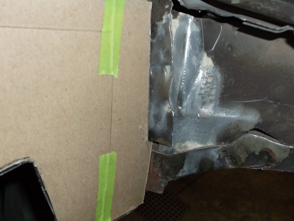
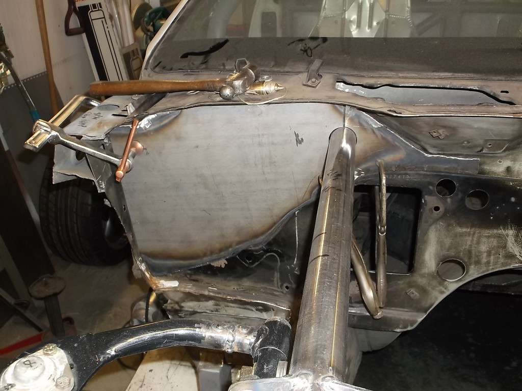
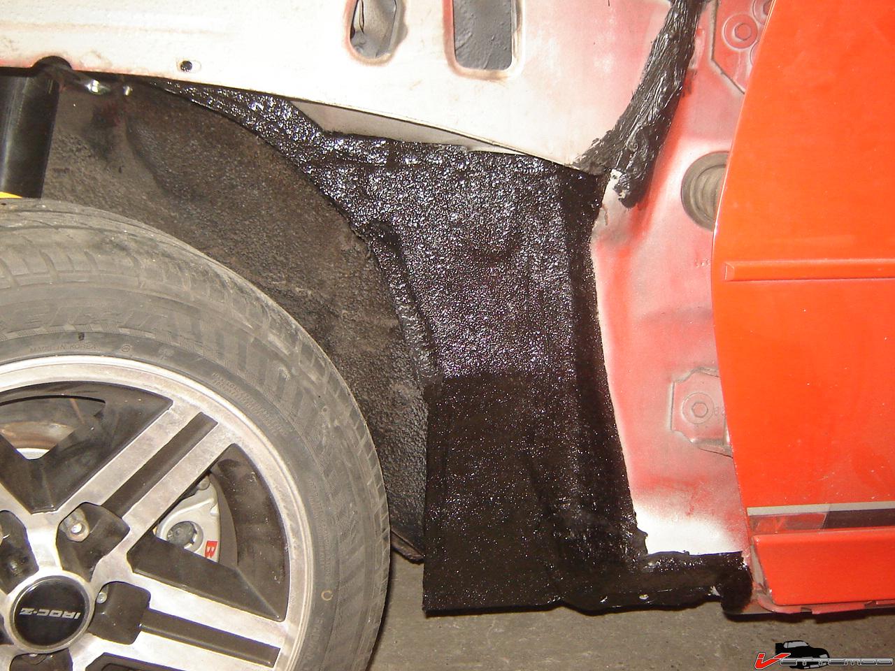
If you think you have a rust free car, maybe think again. In prepping the firewall I had to remove the large blobs of seam sealer applied at the factory. Both bottom outside corners were rusted through behind the sealer with the drivers side being the worst.
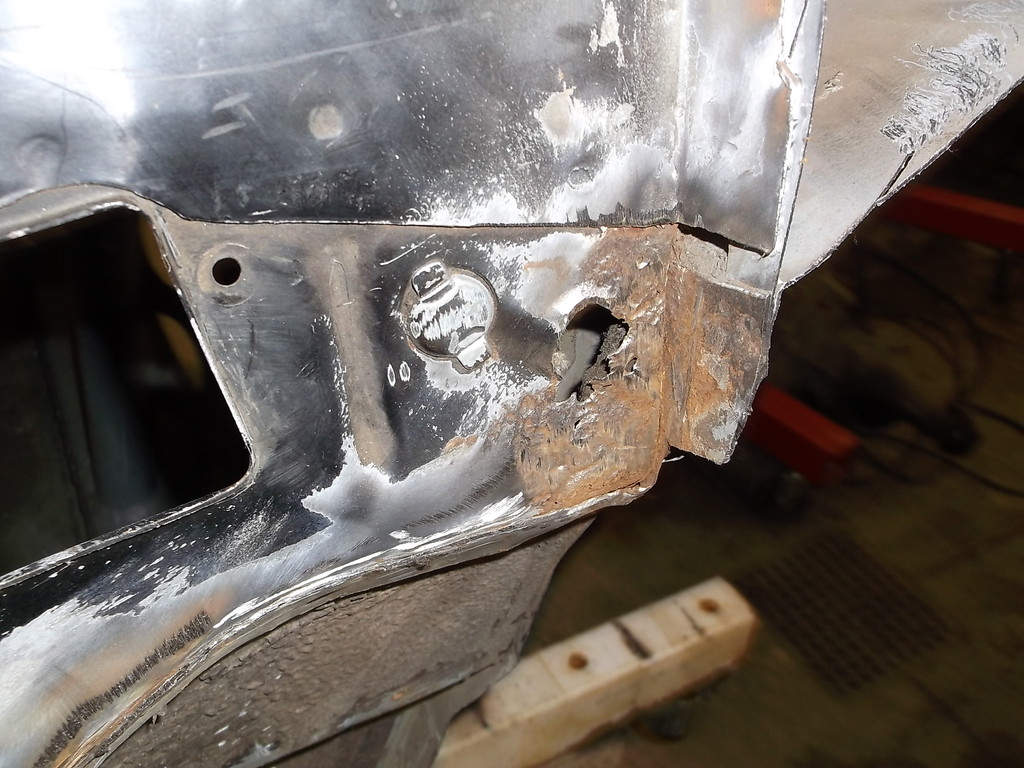
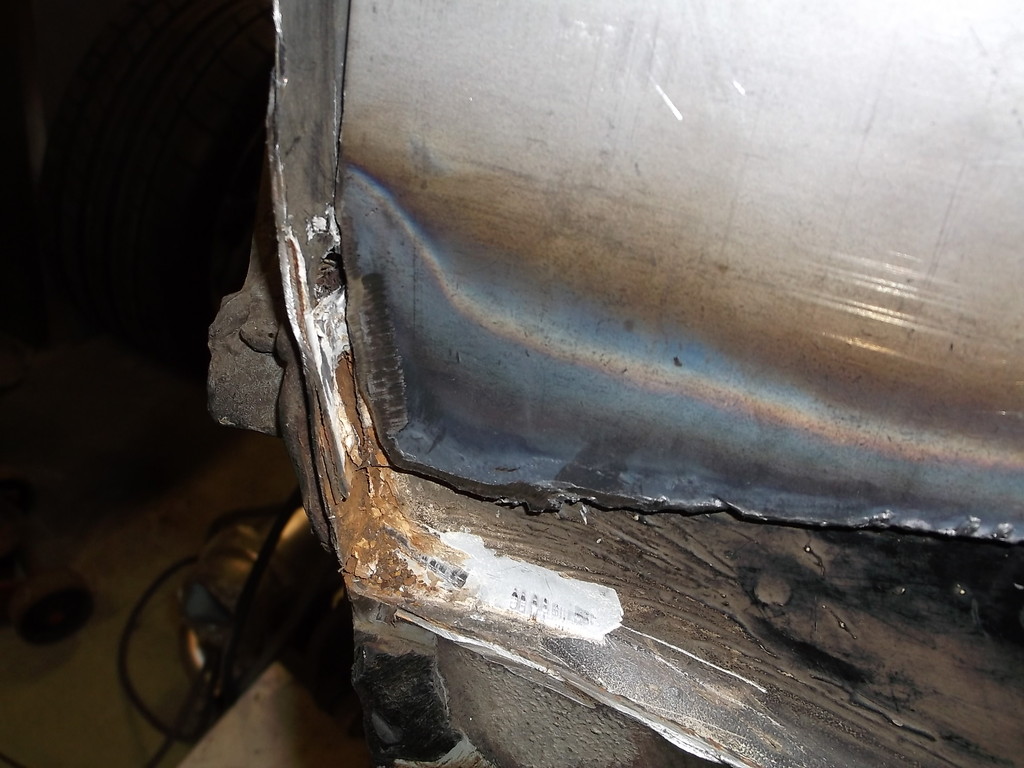
This car was from South Carolina and only spent 3 winters in OH here before I got it. My son's 84 Berlineta was from Oklahoma and was rusted out in the same place on driver side. On his car I could follow a water trail from the area around the hood release cable to the small rusted through area where the floor pan, rocker panel and A pillar meet.
This is a common rust area for these cars and is probably caused by water coming in from the hood cable area, running under the carpet and padding and laying in the seam where the 3 panels join. With the wheel wells in place these areas are almost inaccessible so you would most likely have to seal the driver side from the inside. The passenger side could probably be repaied or sealed with the fender off.

Joined: Jun 2000
Posts: 5,364
Likes: 51
From: Enschede, Netherlands
Car: 82 TA 87 IZ L98 88 IZ LB9 88 IZ L98
Engine: 5.7TBI 5,7TPI 5.0TPI, 5,7TPI
Transmission: T5, 700R4, T5, 700R4
Axle/Gears: 3.08, 3.27, 3.45, 3.27
Re: Home brew road racer
Mine had holes there too, otherwise it was pretty much rust free. The factory seam sealer is a nest for rust. I chiseled all the factory crap out after repairing the spots.
Thread Starter
Senior Member
Joined: Aug 2007
Posts: 682
Likes: 45
Re: Home brew road racer
Yeah, GM laid the sealer on pretty thick to cover up the poor fitment of the body panels. The front of the car was much worse than the rear of the car as far as panel fitment, large gaps and missing spot welds, just real bad quality control. The way the fenders meet the firewall it just makes a large trough for water and salt ( I'm in NE Ohio) to accumulate and slowly eat through. This car spent most of its time down south and still had some rust issues but very minor compared to most cars from this area.
Thread Starter
Senior Member
Joined: Aug 2007
Posts: 682
Likes: 45
Re: Home brew road racer
I want to make a correction to my reply to Basiccamaro. In regards to the upper a-arm position and camber gain. I said in my reply that camber gain is a function of the differing length between the upper and lower a-arms and that is incorrect. The difference in lengths affects the rate of change, as in degree of camber gain per inch of suspension travel. A shorter upper arm will result in a faster rate of change (more camber gain per inch of travel) than a longer arm. The length of the a-arms does not determine the maximum amount of camber gain possible for a certain suspension design.
The total amount of camber gain is determined by the front view swing arm length of the upper and lower a-arms. The longer the swing arm the smaller the change/gain in camber. Think of the angle created by lifting one edge of a ruler 3" off a flat surface and then compare to the angle of a yard stick lifted 3" off a flat surface.
The taller the spindle is the longer the swing arm length will be. The 4th gen spindle is about 18" long and almost 20.5 between the ball joint centers. This makes for a very long swing arm. On graph paper mine works out to be 142" with the lower a-arm horizontal and the upper arm tilted down about 8 degrees. I have about 2 degrees total camber gain over 3 inches of compression travel. I was hoping for more (3 to 4 degrees) but that would require the upper arm set at a 15 to 20 degree angle. I will have to see how well it handles as is, but may need to rework the upper a-arm mount like basiccamaro suggested to get more camber gain.
This is why I appreciate the comments and feed back to my posts. It makes me go back and rethink my design and methods. In the end it makes for a better project and better results.
Thread Starter
Senior Member
Joined: Aug 2007
Posts: 682
Likes: 45
Re: Home brew road racer
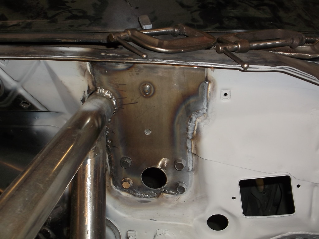
I got the firewall plated finally.
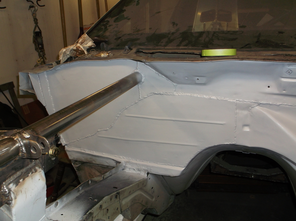
And driver's side
Next will be adding the diagonal tube braces from the top tube rails out to the upper corners of the firewall and the right side tubes behind the upper a-arm mount. Once that is done I will reinstall the engine with the TKO 600 and cut the tunnel for the shifter. That should finish off the major fabrication on this build. I am going to cut it loose from the ramps, roll it outside and give it and the garage a much needed bath!!!!!!!


And driver's side


Next will be adding the diagonal tube braces from the top tube rails out to the upper corners of the firewall and the right side tubes behind the upper a-arm mount. Once that is done I will reinstall the engine with the TKO 600 and cut the tunnel for the shifter. That should finish off the major fabrication on this build. I am going to cut it loose from the ramps, roll it outside and give it and the garage a much needed bath!!!!!!!
Thread Starter
Senior Member
Joined: Aug 2007
Posts: 682
Likes: 45
Re: Home brew road racer
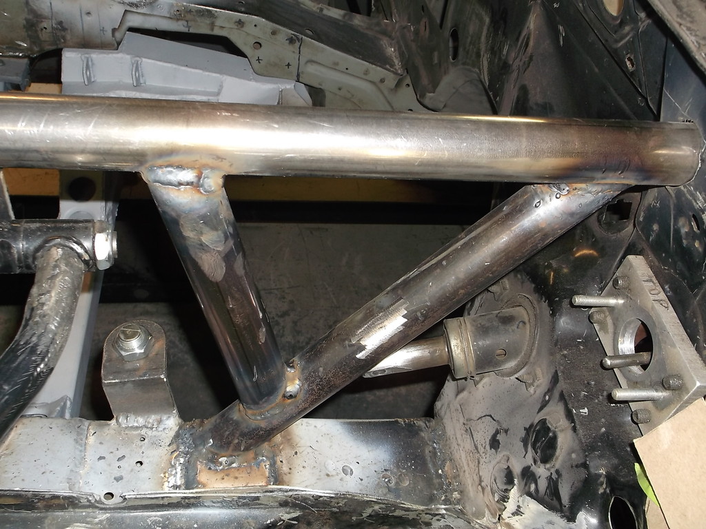
Front end bracing is finally done. I tried to keep the diagonal braces simple and used a 45* angle cut on both ends. Using the length from the firewall forward I projected that distance onto the plated firewall at the corner. To give me room to weld around the tubing I angled the diagonal braces down about 6*. This worked out very well for fitment with minimal notching needed at the upper tube and none needed at the firewall due to its flat surface.
Driver's side
Passenger side
And a top view
I am pretty pleased how this turned out. I think all the bracing will eliminate nearly all flex and twist in the front end and let the suspension react instantly to the road surface.
I want to put the TKO 600 onto the 305 mock up motor and get that in place before I cut it off the ramps. If the stars and planets align maybe sunday afternoon!!!!!!!! Can't wait to see it on the ground again.
Driver's side


Passenger side


And a top view

I am pretty pleased how this turned out. I think all the bracing will eliminate nearly all flex and twist in the front end and let the suspension react instantly to the road surface.
I want to put the TKO 600 onto the 305 mock up motor and get that in place before I cut it off the ramps. If the stars and planets align maybe sunday afternoon!!!!!!!! Can't wait to see it on the ground again.
Thread Starter
Senior Member
Joined: Aug 2007
Posts: 682
Likes: 45
Re: Home brew road racer
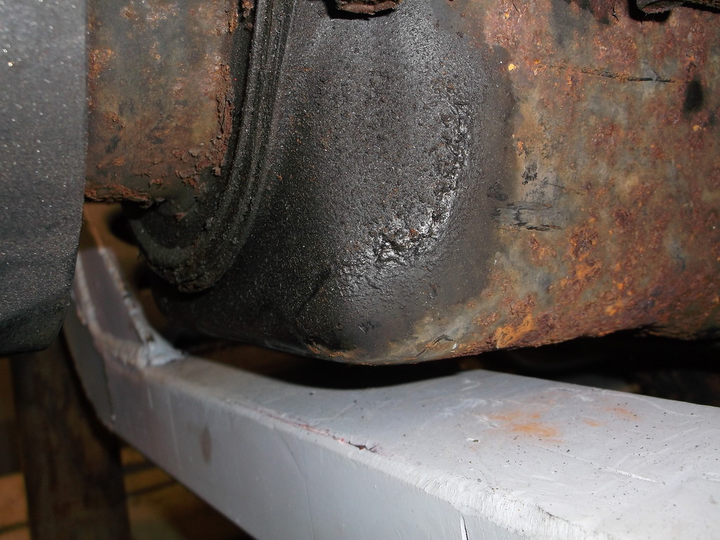
no pictures to post right now but will update. The TKO bolted to the Lakewood bellhousing fine and engine and trans bolted back in the same location as when the 700r4 was in. BUT the tailshaft pointed down into the lower part of the driveshaft loop. Something was clearly not right. I had originally set the engine in so that the carb flange on the intake was dead level front to back and side to side. this gave the engine and trans a little over 2 degree downward slope to the rear. With the TKO bolted in the slope increased to almost 5 degrees down. Since nothing changed at the engine the problem had to be with the trans.
It appears that the mounting pad on the TKO is set much higher up, closer to the tailshaft center line, than on the automatics. With the shifter housing cast into the top of the TKO tailhousing there isn't a lot of room to move the transmission up in the rear without removing most of the front half of the trans tunnel. Even if I could raise it high enough the drive shaft would be hitting the top of the tunnel.
The solution ended up being a combination of lowering the front of the engine about an inch and raising the tailshaft a 1/2". Luckily I had enough oil pan to k-member clearance to drop the front. In the rear I made a 1/2" aluminum spacer to fit between the transmission mounting pad and the urethane trans mount. This got the carb pad back to level and the drive shaft centered back in the tunnel. I'll post pics later this week.
Thread Starter
Senior Member
Joined: Aug 2007
Posts: 682
Likes: 45
Re: Home brew road racer
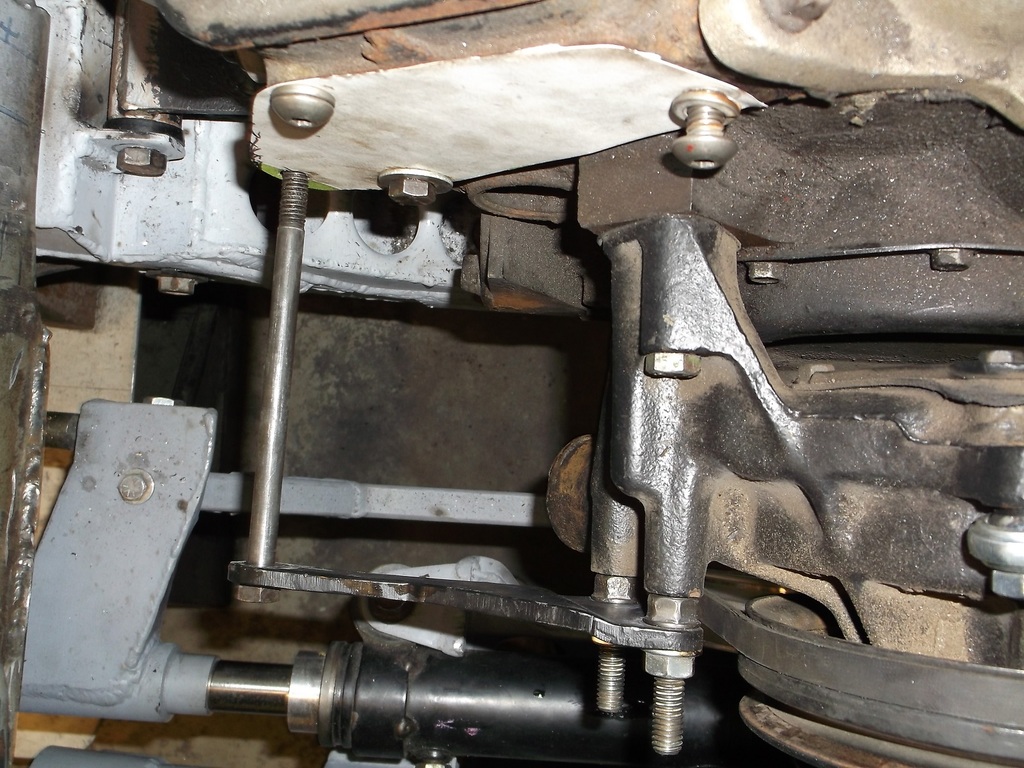
Here are pics of revamped motor and trans mounts.
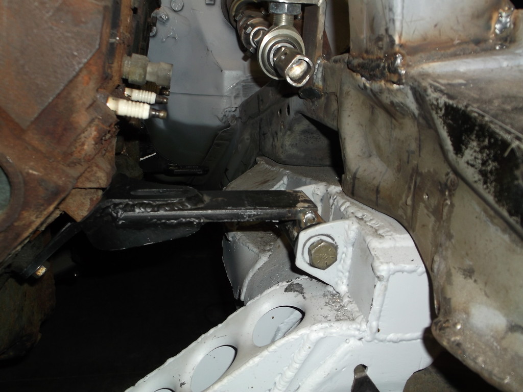
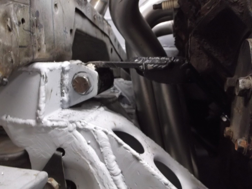
This dropped engine almost 1". Oil pan still clears!!!
Tranny was raised 1/2" with aluminum spacer.
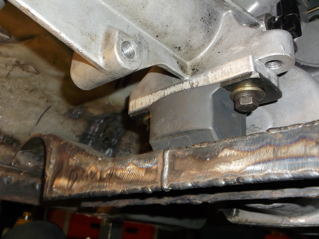
Everything is back in place now.
 .
.


This dropped engine almost 1". Oil pan still clears!!!

Tranny was raised 1/2" with aluminum spacer.

Everything is back in place now.

 .
. Thread Starter
Senior Member
Joined: Aug 2007
Posts: 682
Likes: 45
Re: Home brew road racer
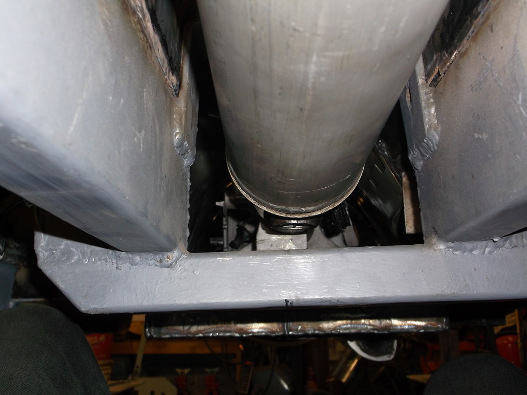
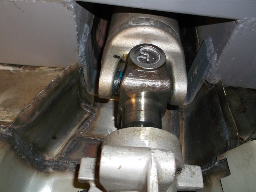
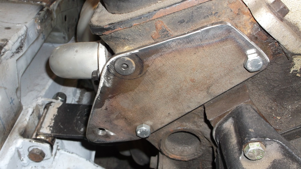
I have been tossing around the idea of running a midmount plate for the sole purpose of tieing the frame rails together below the firewall.
I have a Quick Time 1/4" steel mid plate.
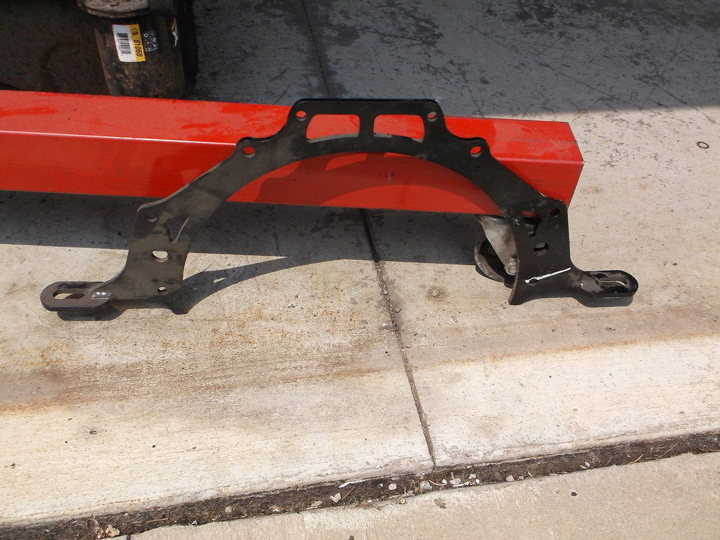
fits like this on engine
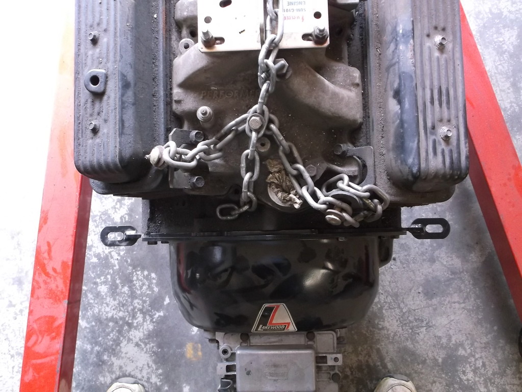
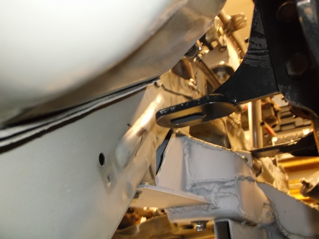
Fits like this in the chassis.
passenger side
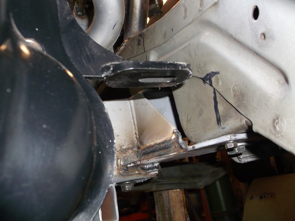
Drivers side
Just not sure if it would be worth the trouble to install and extra work to remove/instal the engine and trans.
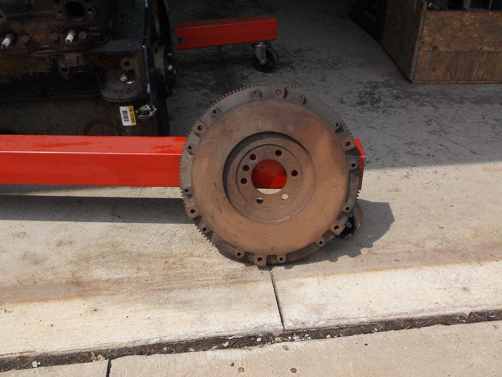
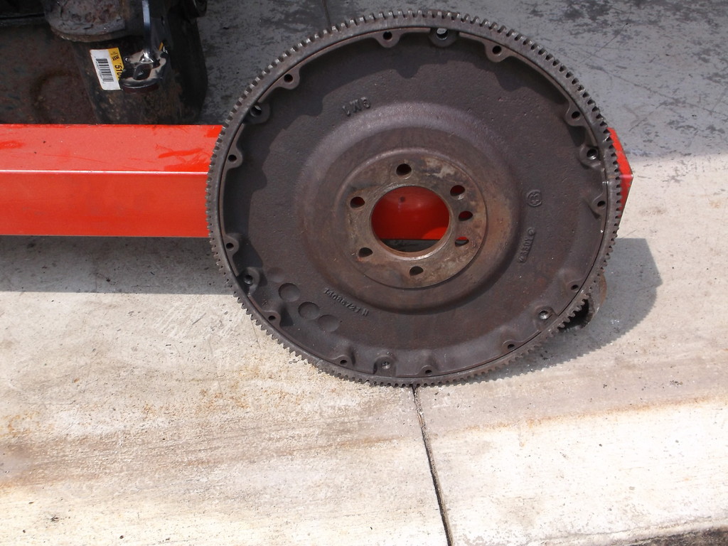
One other goodie I have is a 16lb OE GM flywheel for a 2 piece rear main seal block. It was a part I saved from a stock car we ran in the early 2000's.
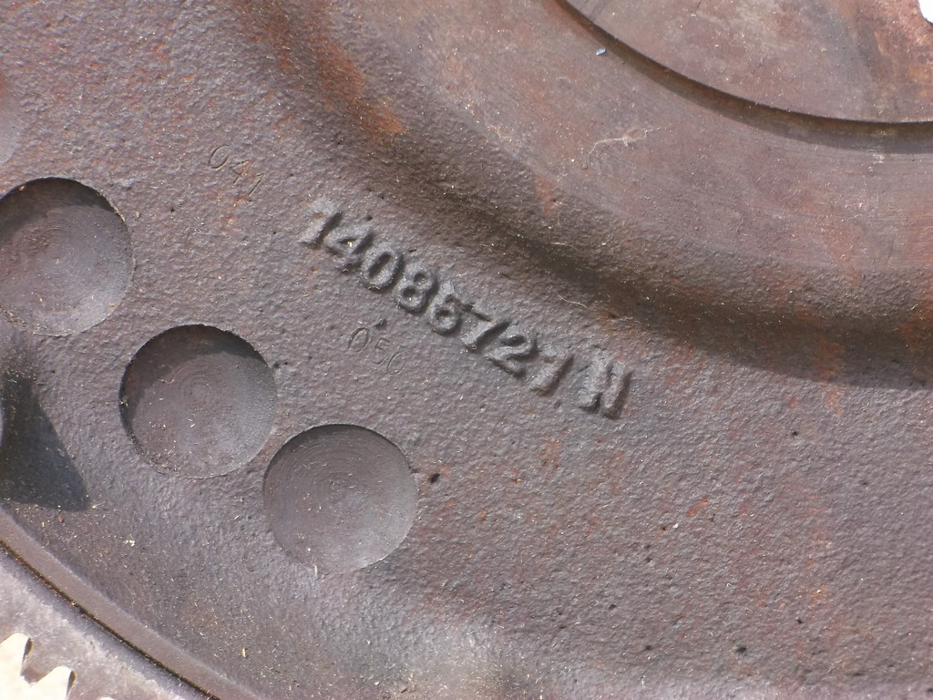
GM part number
I have a Quick Time 1/4" steel mid plate.

fits like this on engine

Fits like this in the chassis.
passenger side

Drivers side

Just not sure if it would be worth the trouble to install and extra work to remove/instal the engine and trans.
One other goodie I have is a 16lb OE GM flywheel for a 2 piece rear main seal block. It was a part I saved from a stock car we ran in the early 2000's.


GM part number

Thread Starter
Senior Member
Joined: Aug 2007
Posts: 682
Likes: 45
Re: Home brew road racer
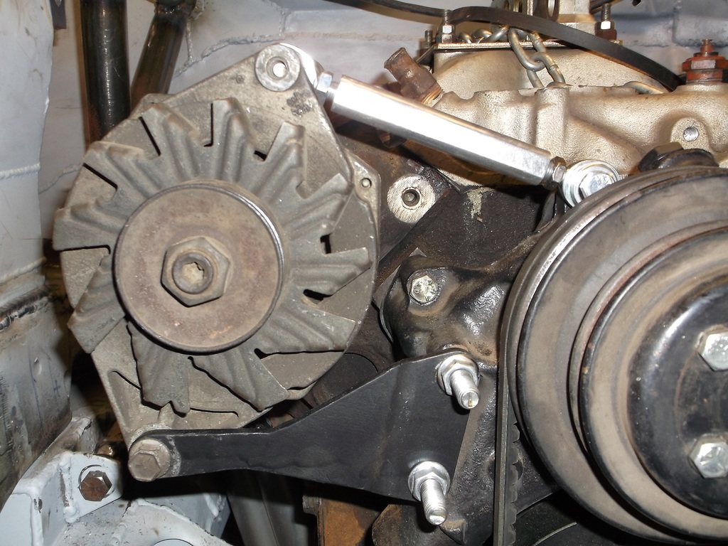
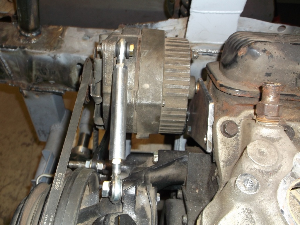
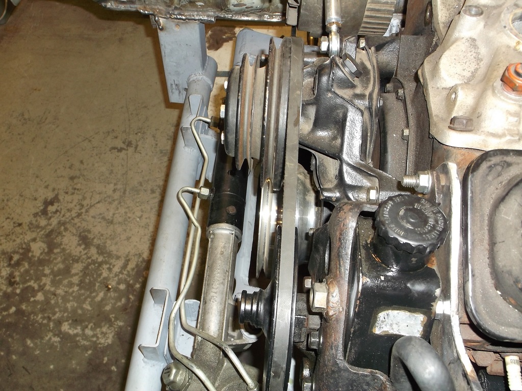
While the car is still welded to the ramps I thought I better check to see if the alternator and power steering pump still fit since the engine was lowered. They didn't but they do now. I originally had the P/S pump mounted to an adjustable billet aluminum bracket and the alternator was mounted low on a modified A.I.R. pump bracket. This let both pieces set low on the engine and both units used the same size fan belt. With the engine lowered both hit the steering rack or linkage. To remedy I reused the factory high mount alt brackets and the p/s pump is hanging off of a modified stock bracket. P/S pump is only mocked in place and needs additional bracing.
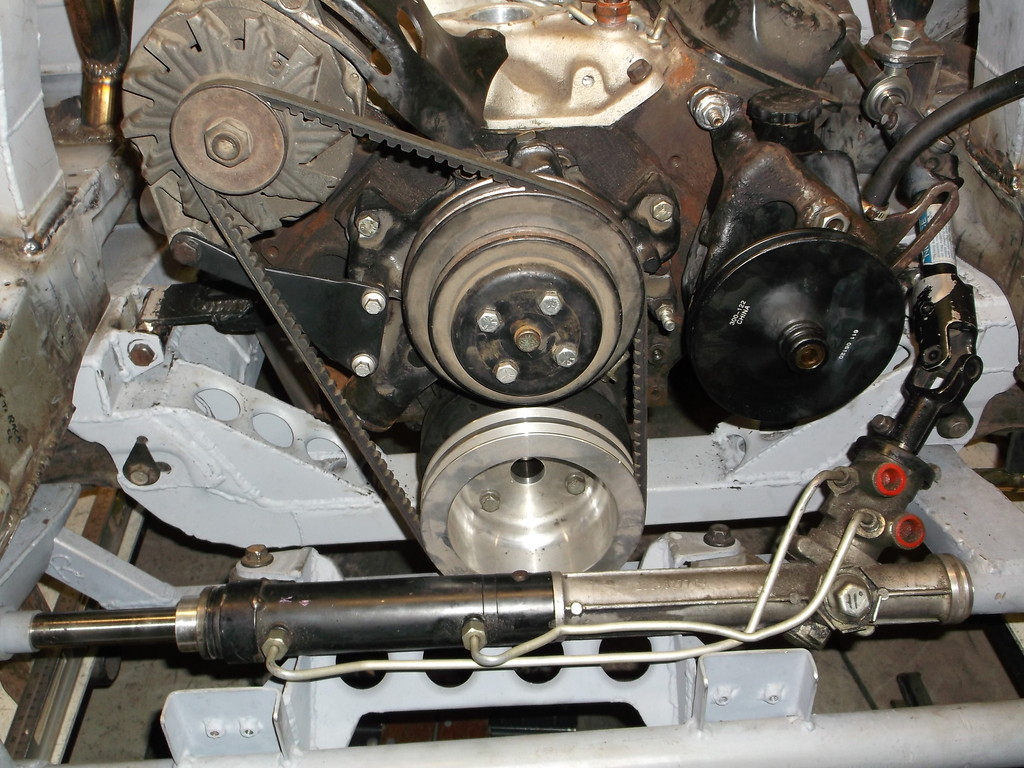
You notice that the crank pulley was changed as well. The smaller diameter pulley that was in place had the 2 V grooves very close together. The water pump pulley is OE and there is about 1/4" between the two grooves. The alluminum pulley in the picture has the proper spacing and even though it looks much larger in OD it is actually only 1/2" larger than the WP pulleys and will give a slight overdrive.

You notice that the crank pulley was changed as well. The smaller diameter pulley that was in place had the 2 V grooves very close together. The water pump pulley is OE and there is about 1/4" between the two grooves. The alluminum pulley in the picture has the proper spacing and even though it looks much larger in OD it is actually only 1/2" larger than the WP pulleys and will give a slight overdrive.

Member
Joined: Aug 2009
Posts: 332
Likes: 0
From: this car
Car: 85 Z28
Engine: 93 LT1
Transmission: Auto
Axle/Gears: 3.73 01 SS
Re: Home brew road racer
Damn you've got a hell of a project going on there. I like the mid-plate idea, though I have no idea how it effects the spacing of the torque converter. I'm sure there's a nifty trick to those. Good work.

Thread Starter
Senior Member
Joined: Aug 2007
Posts: 682
Likes: 45
Re: Home brew road racer
I am going to leave the mid mount plate in for now but would really like to run an x-brace from the ends of the SFC's to the k-member and then to the front cross member. I think this would provide more torsional and lateral rigidity.
Thread Starter
Senior Member
Joined: Aug 2007
Posts: 682
Likes: 45
Re: Home brew road racer
The rear axle is an 8.6 GM unit from a 1999 ZR ST10 truck. They were stock with 30 spline axles, disc brakes, 3.73 gears and the GM gov-lock posi unit. It is about 1 3/4" wider than the 3rd gen and only had the brackets for the leaf springs that needed to be removed.
If you go back to page 3 of my post I have the whole swap is there. I converted the rear suspension to a 3 link and coil overs, all hanging from a 2x3 frame work that was grafted into the stock rear wheels just above the rear axle.
Supreme Member
iTrader: (3)
Joined: Mar 2015
Posts: 1,072
Likes: 48
From: Minnesota
Car: 84 Z28
Engine: 383 Stroker
Transmission: 700R4
Axle/Gears: 3.73
Re: Home brew road racer
(Quote from 83rdracr)
For mostly stock style cars the dimensions to check for frame twist or bend can be found in body repair manuals and on the web. For custom jobs like mine I will have to keep a log book with diagrams of the chassis measurements, suspension mounting locations etc.
I was reading through this and was going to say that!! Before I did any work to my car, I had my body shop guy throw it on a frame rack and pull measurements. I have the print-out somewhere. It was dead on. Said it is better that most new cars that he has worked on. Its a list of every hole and measurement so you know if the body/frame/uni/ect is straight.
Anyways, a guy could use the sheet for a reference for measuring like you are. Making sure everything is plumb and square. Not sure if you can find that on the web, But I know my body guy has it so it can be got maybe through a shop by you?
Thread Starter
Senior Member
Joined: Aug 2007
Posts: 682
Likes: 45
Re: Home brew road racer
Z28 thanks for the info. I will check with the body shop that I had straighten the front frame rails after it was wrecked. They did a great job as everything I checked was straight, square and no twist.
Thread Starter
Senior Member
Joined: Aug 2007
Posts: 682
Likes: 45
Re: Home brew road racer
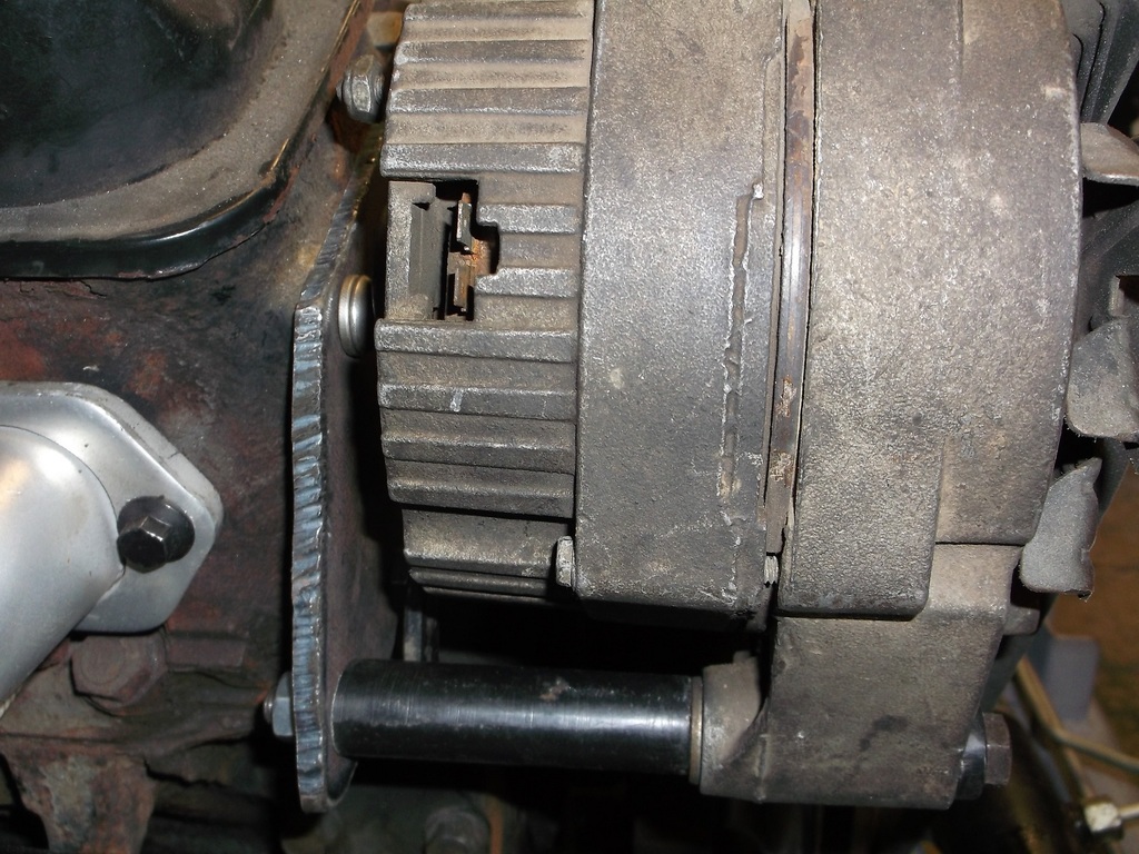
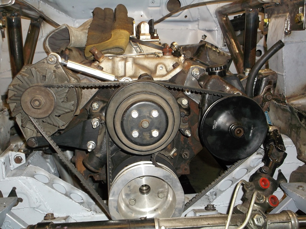
I finished the alt and p/s brackets. I didn't like the alt sitting so high and anchored to the intake manifold. Since I couldn't use the fancy billet p/s bracket I checked to see if the bellcrank adjuster that came with the kit would work on the alt. By flipping the OE lower mount upside down I was able to lower the position of the alt and use the billet adjuster. Had to make a bracket to secure the pivot bolt to the head.
new position of alt with upside down lower bracket and billet adjuster
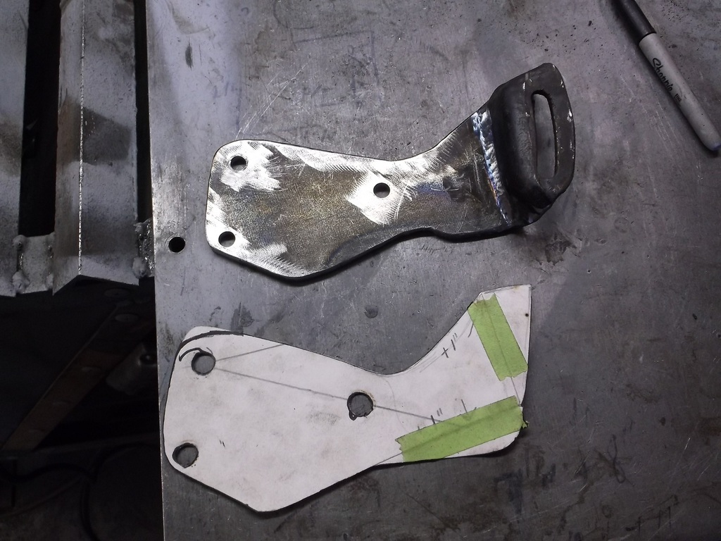
because lower bracket is offset I had to space it out about 3/8". I used a couple of the factory exhaust studs. Perfect!. Made a poster board template for head bracket.
I had to make a similar bracket to secure the p/s pump on the left side and also provide a slotted adjuster to tension the belt. Again, cut and modified OE p/s and a/c bracket that mounted to left side exhaust manifold.
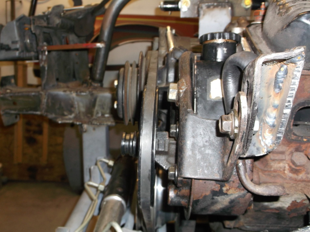
Both units are mounted very sturdy and more symmetrical. I definitely like the lower alt position. Pulley alignment is very good. Cost was almost nothing.
new position of alt with upside down lower bracket and billet adjuster

because lower bracket is offset I had to space it out about 3/8". I used a couple of the factory exhaust studs. Perfect!. Made a poster board template for head bracket.


I had to make a similar bracket to secure the p/s pump on the left side and also provide a slotted adjuster to tension the belt. Again, cut and modified OE p/s and a/c bracket that mounted to left side exhaust manifold.


Both units are mounted very sturdy and more symmetrical. I definitely like the lower alt position. Pulley alignment is very good. Cost was almost nothing.

Thread Starter
Senior Member
Joined: Aug 2007
Posts: 682
Likes: 45
Re: Home brew road racer
I purchased the clutch assembly and hydraulic T/O bearing kit last week so decided to mount the clutch master cylinder and finish the pedals. I was going to go with a Mcleod clutch and T/O kit but when I went to the Summit store I wandered through the scratch and dent area first. They must have known I was coming as I found a Centerforce dual friction kit for a third gen for less than 1/2 price!!!!!. The part is brand new off of a display rack as it only has bolt marks on 3 of the 6 mounting holes and no sign of ever being installed on a flywheel. I did get the Mcleod T/O kit, a very nice setup.
I should mention that the centerforce clutch and the Mcleod T/O kit are not compatible as is. The extra counter weights on the centerforce pressure plate interfere with the larger diameter throwout bearing in the Mcleod kit. The remedy is to remove the extra weights (they just snap off). This fix was recommended by the tech department at Centerforce. I will lose some clamping force at higher rpms but the basic pressure plate still increases the clamping load by about 50% over stock.
Ok so on with the master cylinder install. I had planed to mount the M/C on the small flat area just to the right of the square opening for the engine compartment wiring harness. The diamond shaped mounting flange of the master cylinder was to wide to fit in the space. After scratching my head for a while I decided to just move the opening over to the left one inch.
To locate the M/C I made a poster board template of the mounting flange and transferd that onto the firewall making sure the mounting holes were vertical.
M/C fit like this.
That area of the firewall is not dead flat and it caused a 1/8" gap at the top mounting flange. With the 1/8" steel plating there, no amount of hammering would flatten the mounting surface. I ended up welding a couple 3/8 washers to the firewall with the back washer cut in half to form a wedge. This moved the top of the M/C forward and into mt diagonal brace. A slight turn of the resevoir gave me the needed clearance. Now it doesn't look professional but it fits and will work ok.
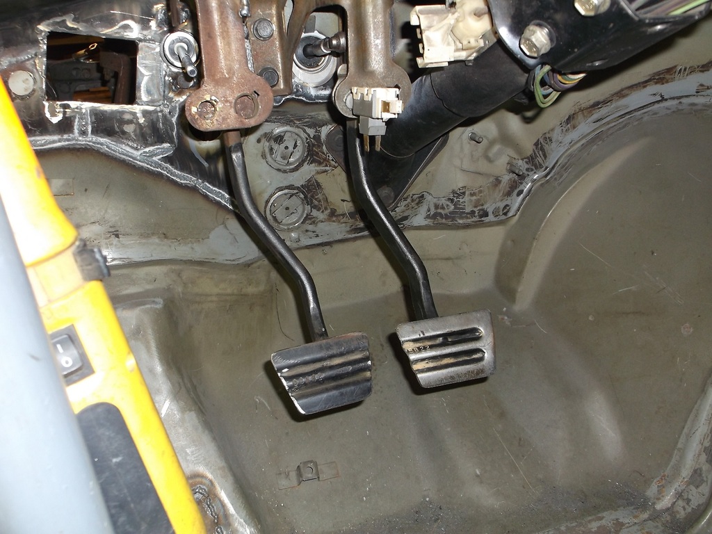
Next was to get the clutch pedal mounted. I had the OE clutch pedal but the pedal arm is bent so the pedal pad is about 2" to the left of the pedal pivot. Because my M/C is offset to the left from the stock position, this put the clutch pedal way to far to the left to be practical. After some more head scratching I decided I could use a slightly modified OE brake pedal as it is offset to the right from the pivot.
To hang the pedal I was able to modify another OE pedal bracket and weld it to the bottom of the cowl.
I should mention that the centerforce clutch and the Mcleod T/O kit are not compatible as is. The extra counter weights on the centerforce pressure plate interfere with the larger diameter throwout bearing in the Mcleod kit. The remedy is to remove the extra weights (they just snap off). This fix was recommended by the tech department at Centerforce. I will lose some clamping force at higher rpms but the basic pressure plate still increases the clamping load by about 50% over stock.
Ok so on with the master cylinder install. I had planed to mount the M/C on the small flat area just to the right of the square opening for the engine compartment wiring harness. The diamond shaped mounting flange of the master cylinder was to wide to fit in the space. After scratching my head for a while I decided to just move the opening over to the left one inch.

To locate the M/C I made a poster board template of the mounting flange and transferd that onto the firewall making sure the mounting holes were vertical.
M/C fit like this.


That area of the firewall is not dead flat and it caused a 1/8" gap at the top mounting flange. With the 1/8" steel plating there, no amount of hammering would flatten the mounting surface. I ended up welding a couple 3/8 washers to the firewall with the back washer cut in half to form a wedge. This moved the top of the M/C forward and into mt diagonal brace. A slight turn of the resevoir gave me the needed clearance. Now it doesn't look professional but it fits and will work ok.


Next was to get the clutch pedal mounted. I had the OE clutch pedal but the pedal arm is bent so the pedal pad is about 2" to the left of the pedal pivot. Because my M/C is offset to the left from the stock position, this put the clutch pedal way to far to the left to be practical. After some more head scratching I decided I could use a slightly modified OE brake pedal as it is offset to the right from the pivot.

To hang the pedal I was able to modify another OE pedal bracket and weld it to the bottom of the cowl.

Thread Starter
Senior Member
Joined: Aug 2007
Posts: 682
Likes: 45
Re: Home brew road racer
The next problem to overcome is mounting the radiator. I have two identical aluminum radiators that were from our chevelle stock car escapades. They measure about 30 1/2 wide and just barely clear the frame rails when mounted vertically in the stock location. I had planned on leaning the top forward so that it would sit inside the nose at or below the headlights. I was going to mount dual fans pointing up and ducting the air out through vents on both sides of the cowl hood.
To get the clearance I need to lean the radiator forward I would need to narrow both frame rails at least 1/2" and replate them. This is doable but more work than I had planned on. The other alternative is to get a 28" wide triple pass radiator that would fit with no frame mods but really reduces the core size and fan options. I really hate to buy another radiator when I have one new and one good used radiator on hand. decisions. decisions.
To get the clearance I need to lean the radiator forward I would need to narrow both frame rails at least 1/2" and replate them. This is doable but more work than I had planned on. The other alternative is to get a 28" wide triple pass radiator that would fit with no frame mods but really reduces the core size and fan options. I really hate to buy another radiator when I have one new and one good used radiator on hand. decisions. decisions.
Supreme Member
iTrader: (3)
Joined: Mar 2015
Posts: 1,072
Likes: 48
From: Minnesota
Car: 84 Z28
Engine: 383 Stroker
Transmission: 700R4
Axle/Gears: 3.73
Re: Home brew road racer
Check this out, I should prob put this on the fab board, but I wanted you to see this.. You have your steering together so you dont need this but it sure gives a guy more options when doing what you are or any motor swap..
http://www.ebay.com/itm/2000-Nissan-Pathfinder-3-3L-V6-Steering-Transfer-Gear-/261753519566?hash=item3cf1b9bdce&vxp=mtr
(edit) Rag joints go on either end so you dont have to mess with splines ect..
http://www.ebay.com/itm/2000-Nissan-Pathfinder-3-3L-V6-Steering-Transfer-Gear-/261753519566?hash=item3cf1b9bdce&vxp=mtr
(edit) Rag joints go on either end so you dont have to mess with splines ect..
Last edited by -=Z28=-; Aug 5, 2015 at 02:01 PM.
Thread Starter
Senior Member
Joined: Aug 2007
Posts: 682
Likes: 45
Re: Home brew road racer
Check this out, I should prob put this on the fab board, but I wanted you to see this.. You have your steering together so you dont need this but it sure gives a guy more options when doing what you are or any motor swap..
2000 Nissan Pathfinder 3 3L V6 Steering Transfer Gear | eBay
(edit) Rag joints go on either end so you dont have to mess with splines ect..
2000 Nissan Pathfinder 3 3L V6 Steering Transfer Gear | eBay
(edit) Rag joints go on either end so you dont have to mess with splines ect..
Thread Starter
Senior Member
Joined: Aug 2007
Posts: 682
Likes: 45
Re: Home brew road racer
I finished up the clutch pedal, got a 5/16 rod end and drilled the pedal arm. Because the clutch m/c is mounted at a slight angle I could not set the pin as high as wanted. Mcleod recommends a 6 to 1 pedal arm ratio which would set the clevis pin down 2" from the pedal arm pivot pin. Because of the angle of the clutch m/c I had to settle on 3" down from the pedal arm pivot which gives me a 4 to 1 pedal arm ratio. A little more effort but a little less travel. I will need to make pedal stops for the clutch pedal.
I also countersunk a couple mounting holes on the alt and p/s brackets to gain a little more clearance on the back side of the units.
Back of p/s pump
Back of alternator

I also countersunk a couple mounting holes on the alt and p/s brackets to gain a little more clearance on the back side of the units.


Back of p/s pump

Back of alternator

Thread Starter
Senior Member
Joined: Aug 2007
Posts: 682
Likes: 45
Re: Home brew road racer
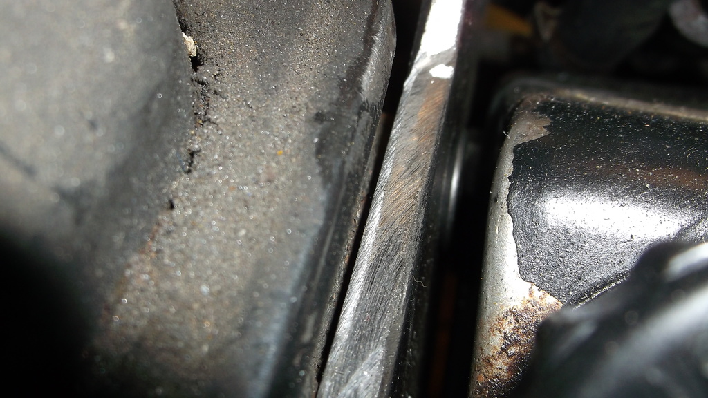
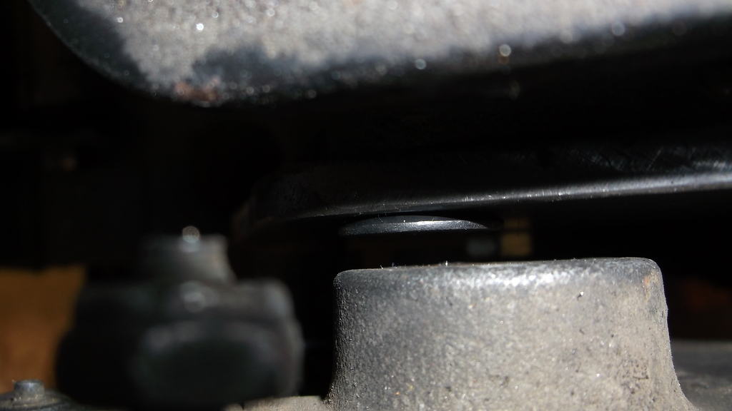
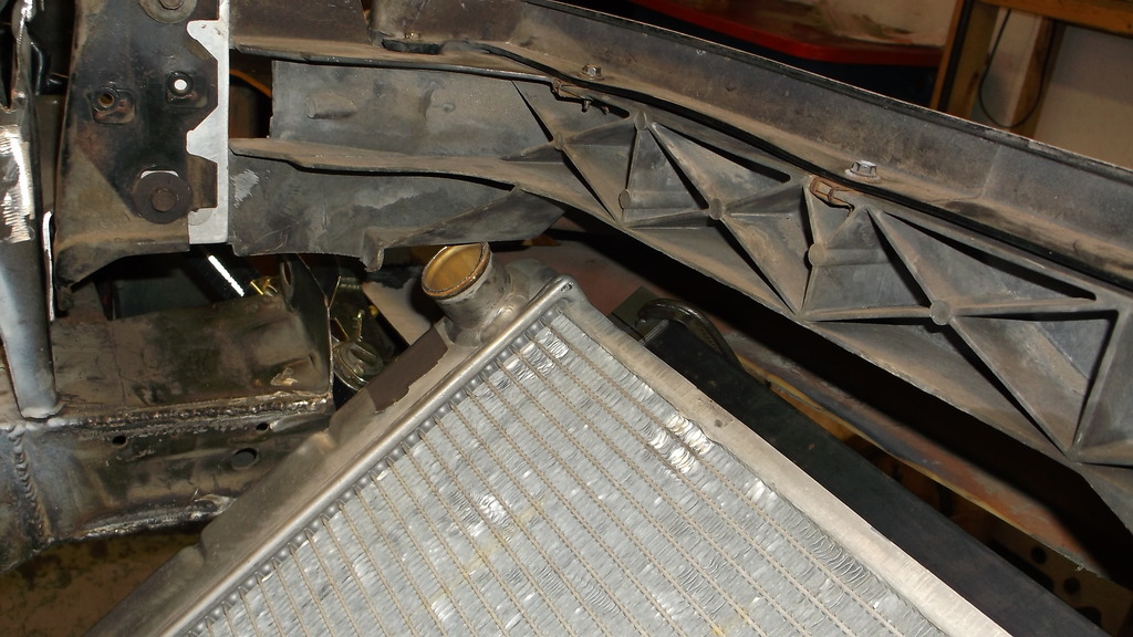
The car gods smiled upon me again. I had resigned myself to mounting the radiator I had on hand in a vertical position in about the stock location. After trimming away some of the core support and the temporary brackets I dropped the radiator between the rails and realized the big radiator could lay forward like I hand wanted it to!!!! After what seemed like hours I finally got it positioned under the nose and the top of the radiator is now level with the top of the grill opening. I cut out the license plate mount and left a 1" lip all the way around.
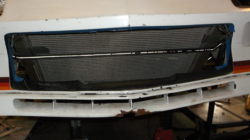
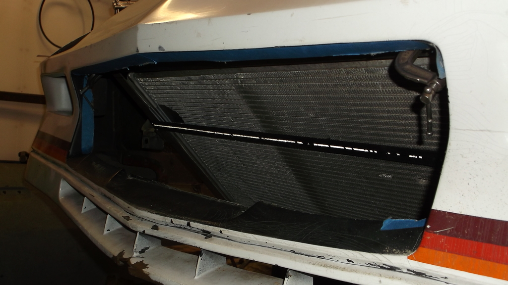
I will fab up some aluminum duct work that will attach to the bottom of the radiator mounts and fit around the upper and lower grill openings. This is going to be a "front feeder" with no air inlet under the car like the factory used.
This is a tight fit at the top of the radiator and required that I cut off the filler neck. I will have my local weld shop weld the hole shut and use a remote fill at the thermostat housing. It will also require that I clearance the fiberglass mount that holds up the center of the nose. It sits right on top of the upper hose.
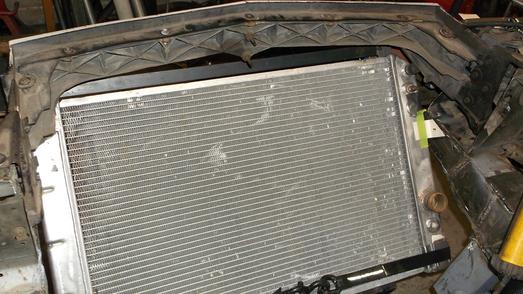
This should be the last major component that I have to mount. once this is done I will cut the car loose and roll it outside. I want to roll it onto the scales and see what kind of weight distribution I have. Once that is done I will pull the engine and trans, remove the suspension front and rear, drop the k-member, and sand blast and paint the under carriage and engine compartment. Once that is done I can start a final assembly of the drive train and suspension, and get all of the fuel and brake systems plumbed in.
The plan is to have this thing running by spring and on the road next summer.
"If you want to make God laugh just tell him your plans."


I will fab up some aluminum duct work that will attach to the bottom of the radiator mounts and fit around the upper and lower grill openings. This is going to be a "front feeder" with no air inlet under the car like the factory used.
This is a tight fit at the top of the radiator and required that I cut off the filler neck. I will have my local weld shop weld the hole shut and use a remote fill at the thermostat housing. It will also require that I clearance the fiberglass mount that holds up the center of the nose. It sits right on top of the upper hose.


This should be the last major component that I have to mount. once this is done I will cut the car loose and roll it outside. I want to roll it onto the scales and see what kind of weight distribution I have. Once that is done I will pull the engine and trans, remove the suspension front and rear, drop the k-member, and sand blast and paint the under carriage and engine compartment. Once that is done I can start a final assembly of the drive train and suspension, and get all of the fuel and brake systems plumbed in.
The plan is to have this thing running by spring and on the road next summer.
"If you want to make God laugh just tell him your plans."
Member
Joined: Dec 2013
Posts: 388
Likes: 1
From: Athens, Ohio
Car: 1985 Z28
Engine: Turbo 5.3
Transmission: 4l80e
Axle/Gears: Ford 9"
Re: Home brew road racer
Just read through the whole thread tonight and you are one hell of a fabricator. This has given me a lot of motivation to start on my rear suspension redesign project.
Can't wait to see yours done
Can't wait to see yours done
Thread Starter
Senior Member
Joined: Aug 2007
Posts: 682
Likes: 45
Re: Home brew road racer
84LSX, thanks for looking in. The fabrication thing came out of necessity, as I don't have the money to buy the BMR, Spohn, Moser stuff. Also I wanted to do something a "little" different.
One reason I posted this build was to show others that you can make/buy a lot of this stuff on the cheap with just normal hand tools and a little imagination and research. If a guy wants tubular rear lower control arms he doesn't have to shell out $200.00 for ready made stuff if he just measures the length he need and picks out the correct size threaded tubes and rod ends from companies like QA1 and Allstar. He can get just as good quality, less the powdercoating for less than half the price. Same can be done for the panhard bar and if the owner can use a welder and a grinder he can easily make subframe connectors and lca relocation brackets as well. These have been shown in this forum many times.
So get your car up on jack stands and tear into it. Cold weather is coming and if you start now you could be back behind the wheel come spring or summer.
Dave