
Home brew road racer


Thread Starter
Senior Member

Joined: Aug 2007
Posts: 682
Likes: 45
Re: Home brew road racer
Scooter thanks for crashing my party. You are correct. It would have to be a ZF from a 1989 vette.
I am not a vette expert by any means (above my pay grade) and was taking my friends word for it. The trans itself was not at his garage, only the bellhousing which I brought home. From the pictures I have looked at on the web It appears to be for the ZF.
That being said it looks like a very strong trans and if it does not take a lot of major changes to make it work I will give it a try. Specs on the web say it weighs 160lbs, about the same for the 700R4 and compared to the TKO 600 at about 105lbs its a porker. If I cant come up with the TKO I would rather have the 6 speed ZF rather than the 4 speed 700R4 at the same weight.
Thread Starter
Senior Member
Joined: Aug 2007
Posts: 682
Likes: 45
Re: Home brew road racer
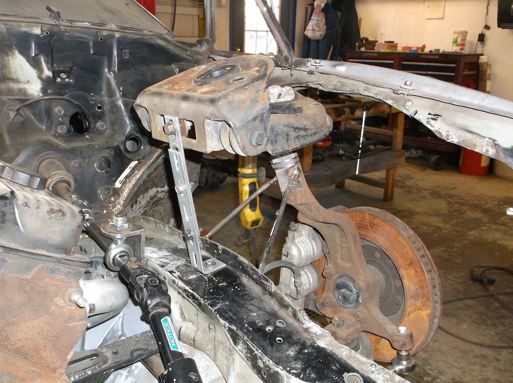
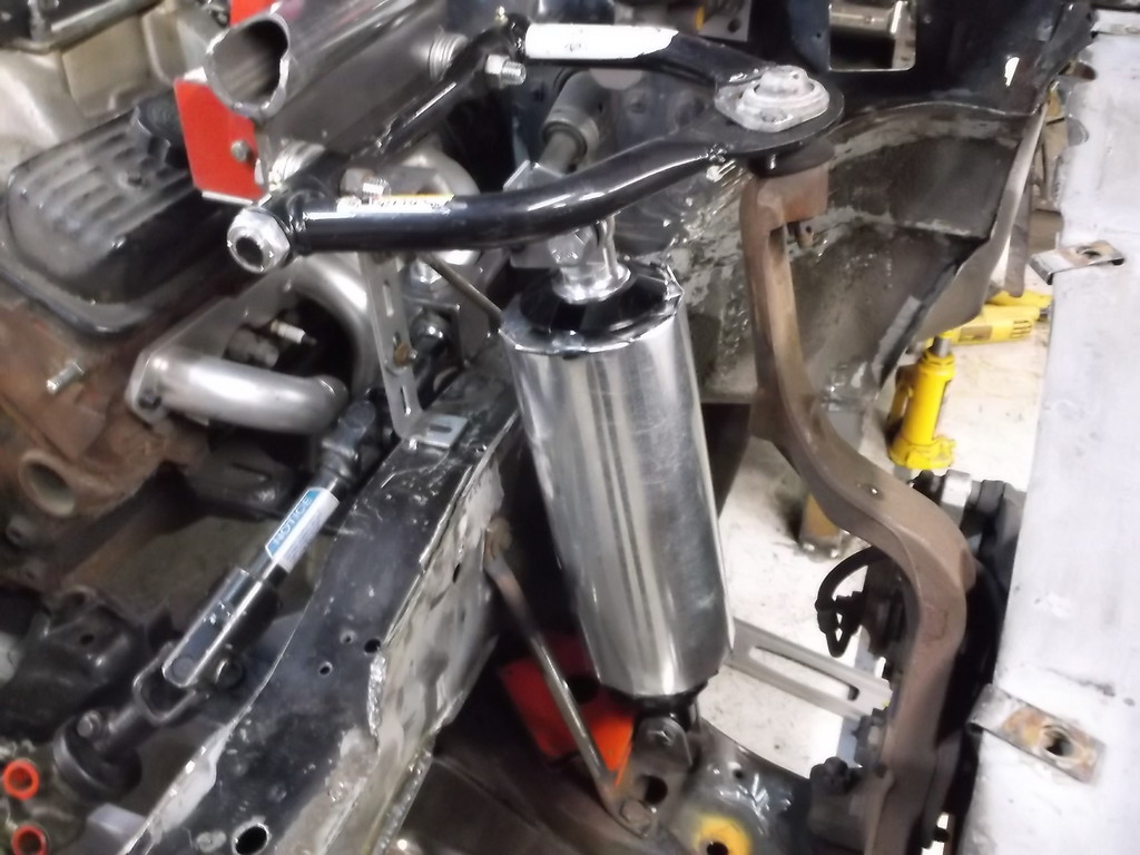
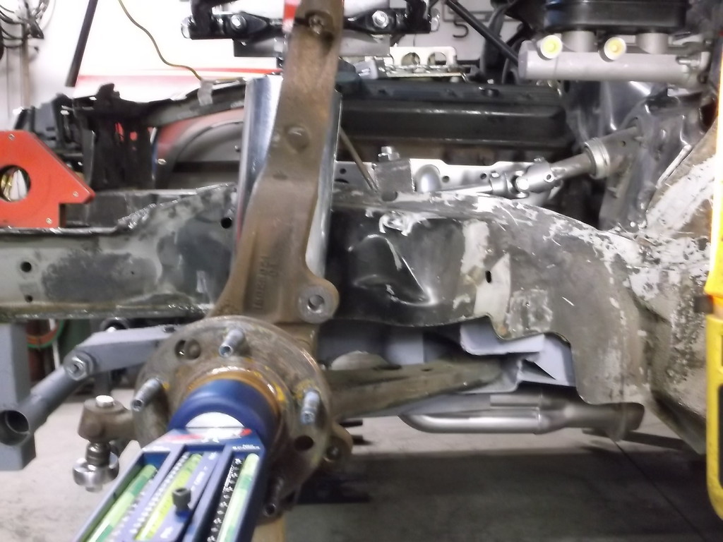
I had the k-member back in the car for some clearance checks and thought I would bolt in the left side a-arm and spindle to make sure everything was still in its right place.
Still lines up!!!!!
I got double adjustable coil-over shocks for Christmas (isn't that what we all want?) and just laid them in place for a trial fit. They are same length as rear shocks at 17" fully extended. I set the length here at about 15" eye to eye to get an idea of where the top mount will be.
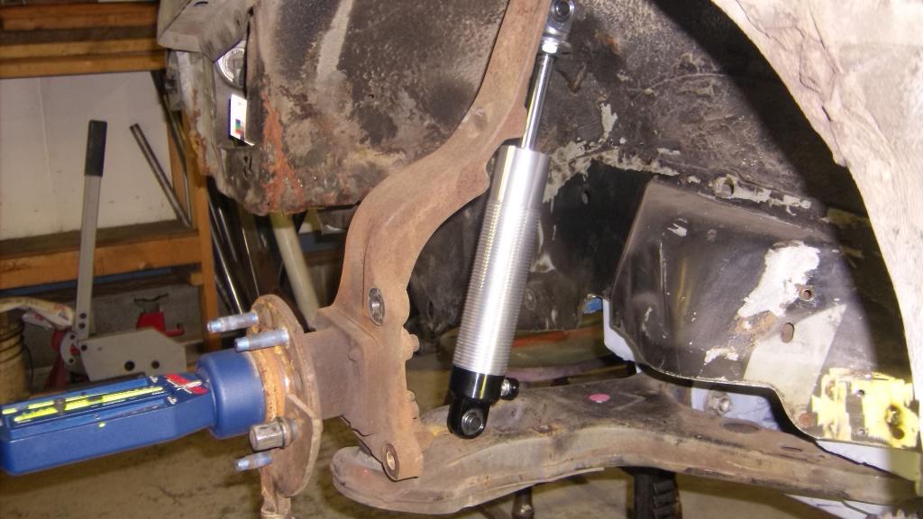
The factory LS coilover assembly mounted about midway between the ball joint and the a-arm bushing. I am hopping that the smaller OD of the QA1 units will let me move it closer to the ball joint. This is about 2 inches closer to the ball joint.
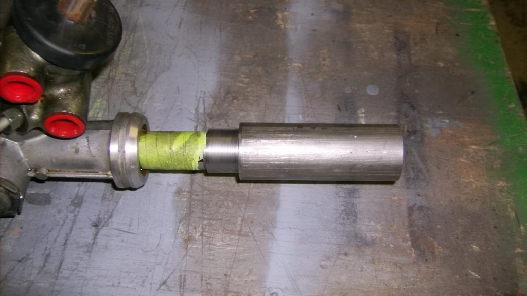
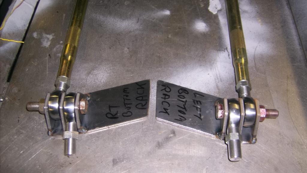
Here are a couple pics of the rack adapters the local machine shop made for me.
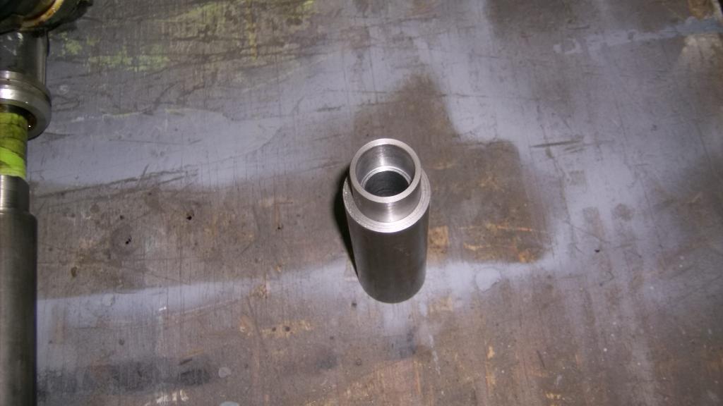
Still lines up!!!!!

I got double adjustable coil-over shocks for Christmas (isn't that what we all want?) and just laid them in place for a trial fit. They are same length as rear shocks at 17" fully extended. I set the length here at about 15" eye to eye to get an idea of where the top mount will be.

The factory LS coilover assembly mounted about midway between the ball joint and the a-arm bushing. I am hopping that the smaller OD of the QA1 units will let me move it closer to the ball joint. This is about 2 inches closer to the ball joint.

Here are a couple pics of the rack adapters the local machine shop made for me.


Thread Starter
Senior Member
Joined: Aug 2007
Posts: 682
Likes: 45
Re: Home brew road racer
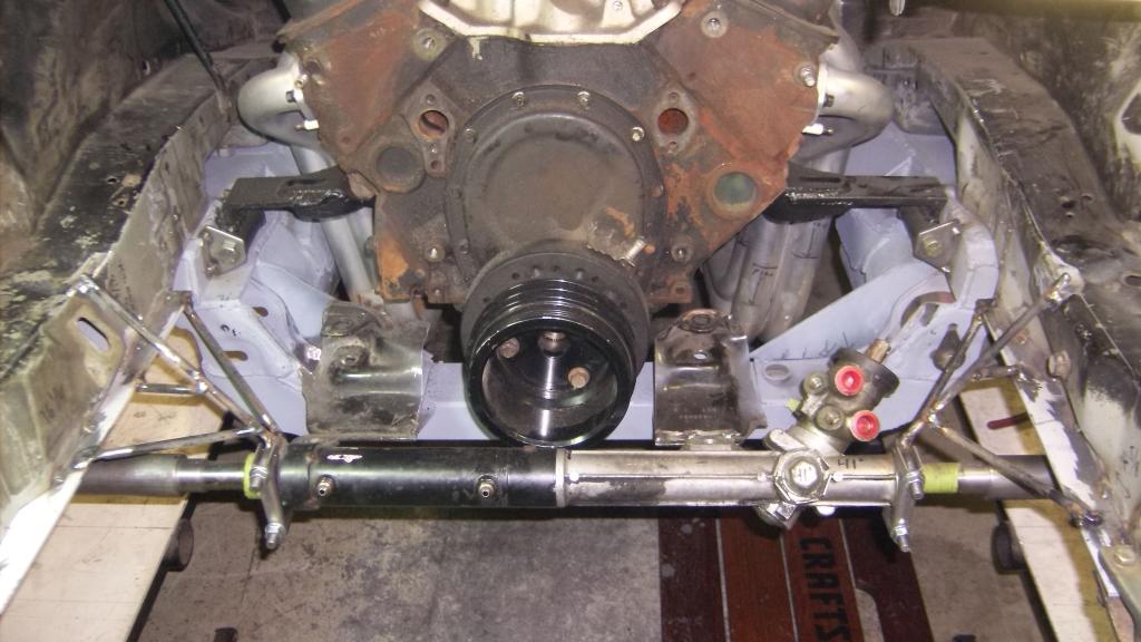
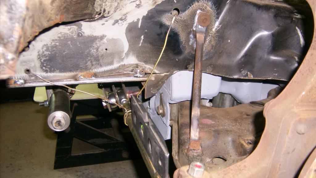
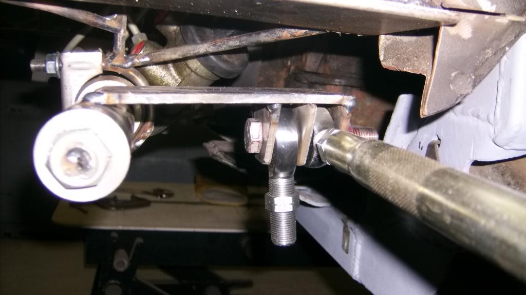
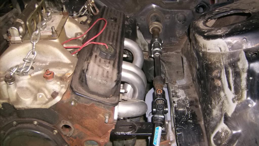
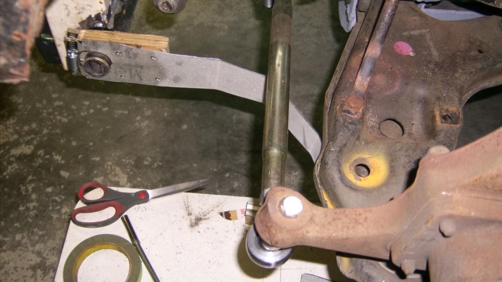
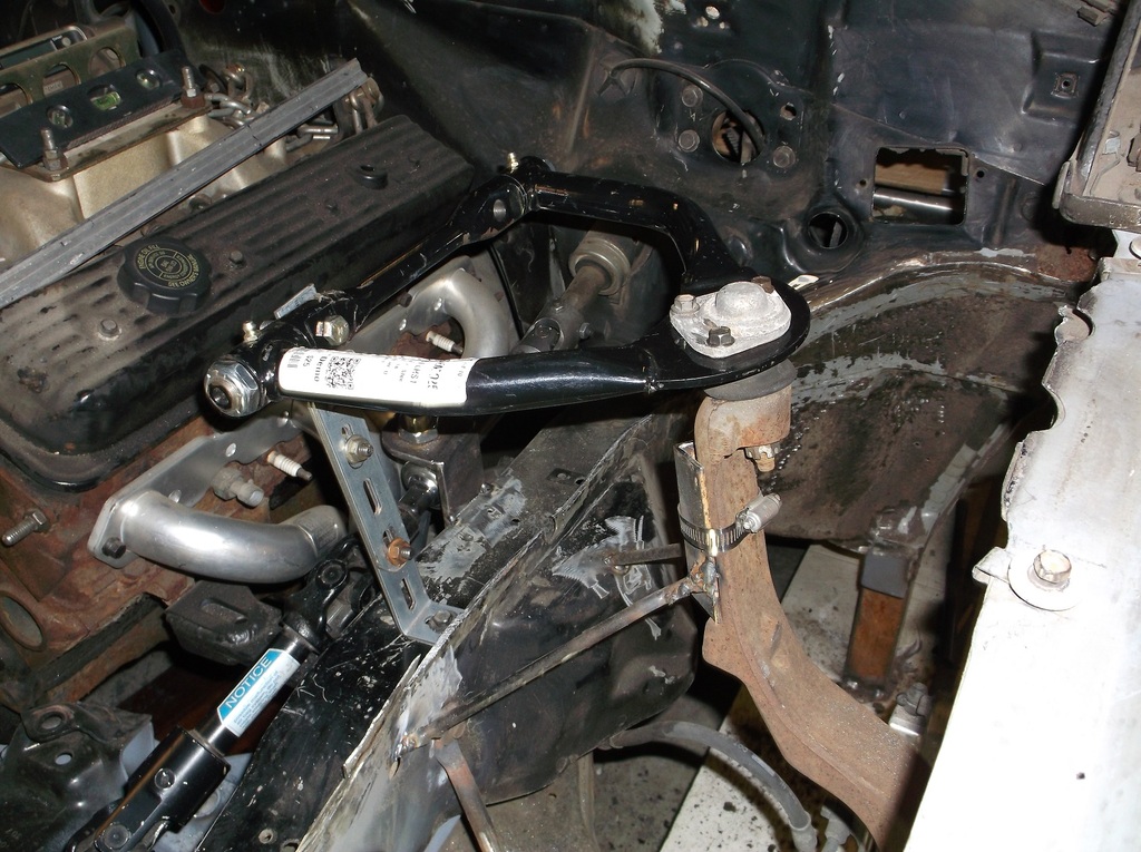
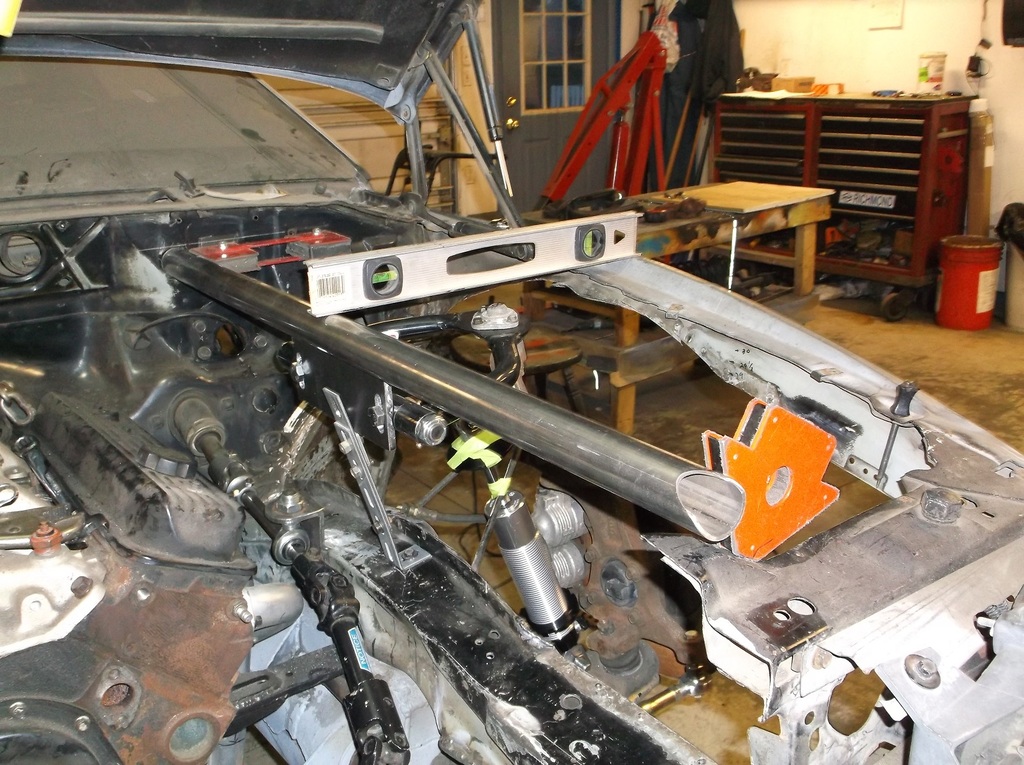
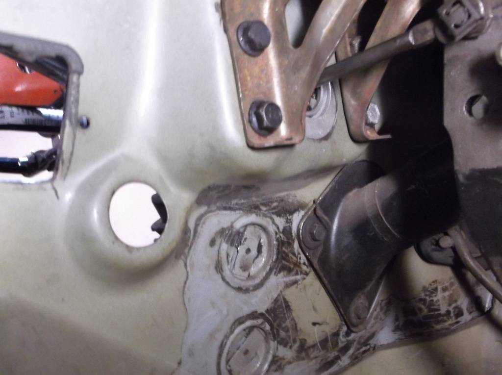
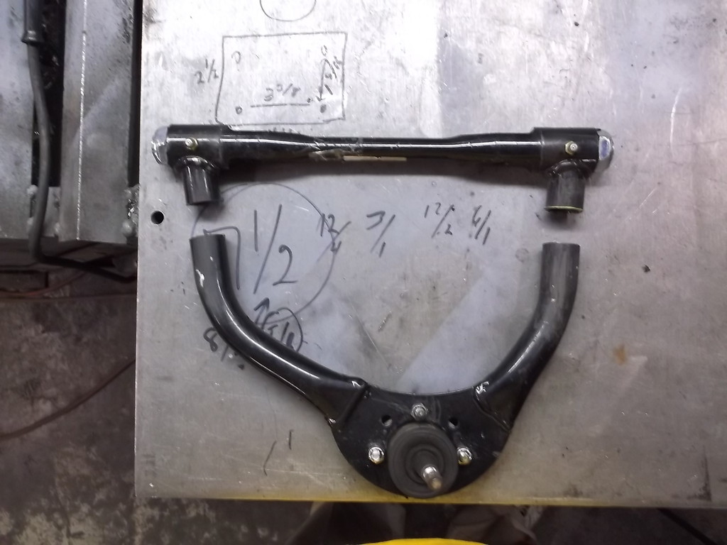
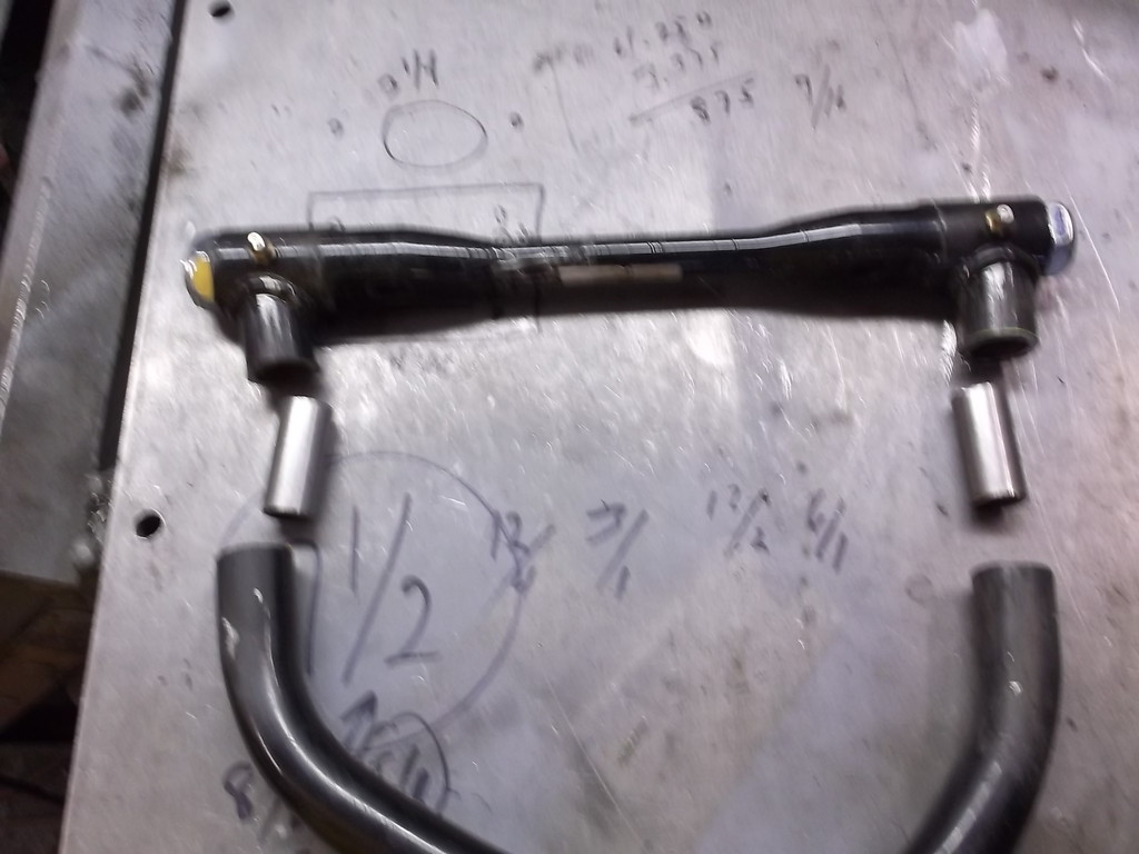
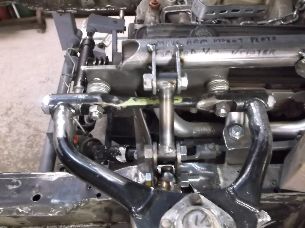
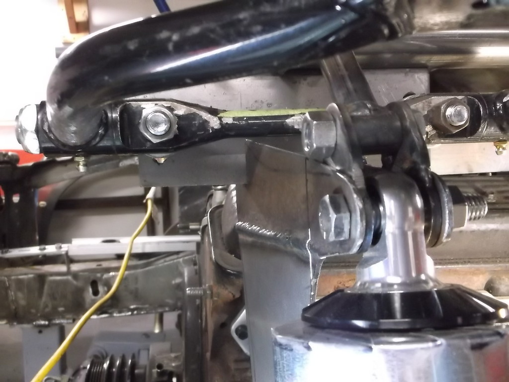
I put the rack back in place and double checked the clearance between the steering input shaft, the new engine mounts and the headers and everything looks good. I mocked up the tie rod one last time before I take a knife to the front frame horns.
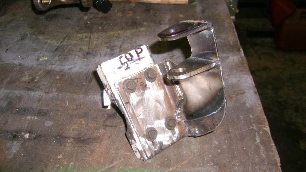
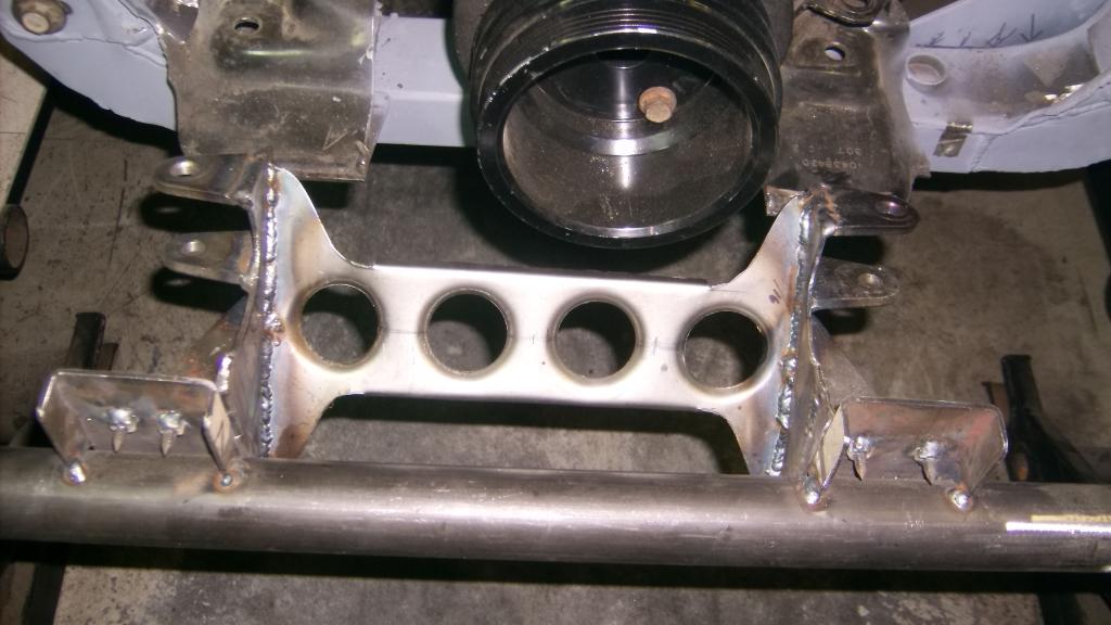
here is new tie rod. The three metal plates will weld to the bottom of the steel plate that will extend back from the rack and position the tie rod back to its original location.
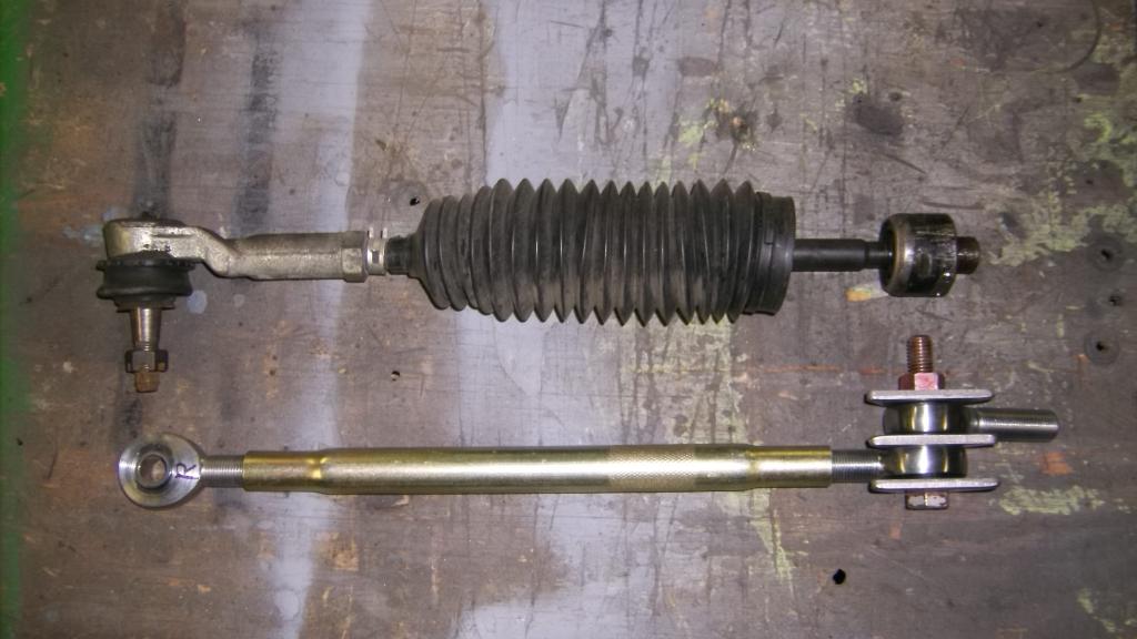
The second heim joint is for the connecting rod that will run between the right and left tie rods. I am counting on the link to prevent any flex due to the extensions on the rack ends. I will also have this center link run through a guide to stop any up and down (vertical forces caused by the path of the steering arm.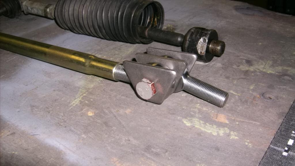


Supreme Member


Joined: Jan 2012
Posts: 2,027
Likes: 33
From: Washington State
Car: 1983 BB 1995 Z28 Camaro's
Engine: 454-350
Transmission: TH350-4l60e
Axle/Gears: 373 posi-Stock
Re: Home brew road racer
Holey crap just read through your hole thread. Great work and very inspiring to me. Looking forward to more updates. Looking forward to the finished product.

Joined: Sep 1999
Posts: 4,353
Likes: 308
From: NJ
Car: 92 Firebird
Engine: 4.8 LR4
Transmission: T56
Axle/Gears: 3.45 9 Bolt
Re: Home brew road racer
That being said it looks like a very strong trans and if it does not take a lot of major changes to make it work I will give it a try. Specs on the web say it weighs 160lbs, about the same for the 700R4 and compared to the TKO 600 at about 105lbs its a porker. If I cant come up with the TKO I would rather have the 6 speed ZF rather than the 4 speed 700R4 at the same weight.
Long time creeper in your thread though

Thread Starter
Senior Member
Joined: Aug 2007
Posts: 682
Likes: 45
Re: Home brew road racer
Scooter, thanks for following along. This has been a long journey. The vette zf does not have a traditional trans mount but rather two vertical bolts similar to a 3rd gen torque arm mount at the diff. I did some research on these and weight is 145lbs of trans less bell and clutch. Also the dual mass flywheel was to correct a gear noise problem. Centerforce and Mc Leod make solid flywheel replacements.
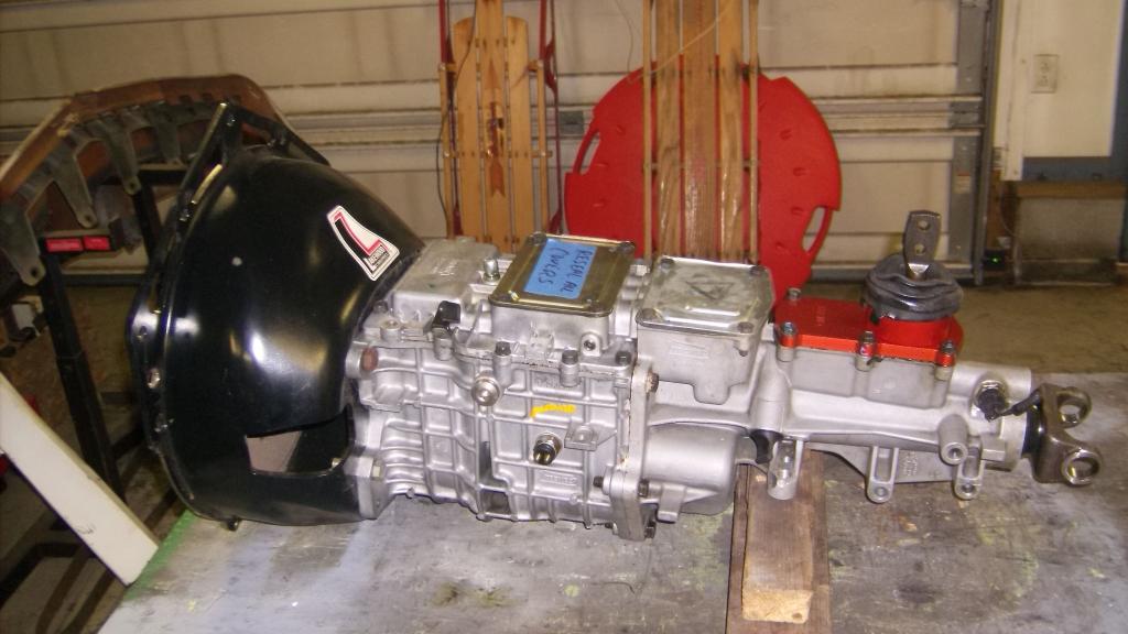
This is all probably moot though as I picked up the trans on Saturday and the extent of the fire damage was greatly understated.
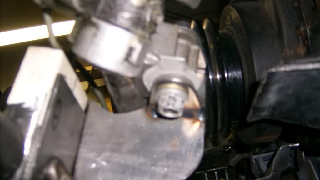
Tail housing got so hot the aluminum melted like candle wax. Totally destroyed the shifter which is a separate piece not cast into the tailhousing like tremec or t56.
Here is what I got.
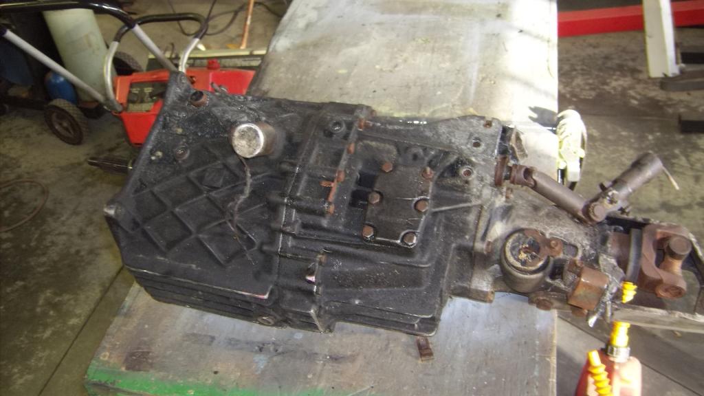
can't tell if this is black or blue tag.
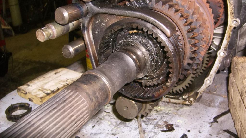
Once I got the the tailhousing and the rear case apart I found more problems that will probably kill the deal. The heat, while not harming any of the metal parts melted every plastic piece inside. It appears that nearly every roller bearing had a plastic cage to contain the rollers. The trans is locked up because the plastic has melted and resolidified, fusing the gears and synchros together.
This was the reverse sprag. It had a plastic cage that fused to the output shaft support bearing.
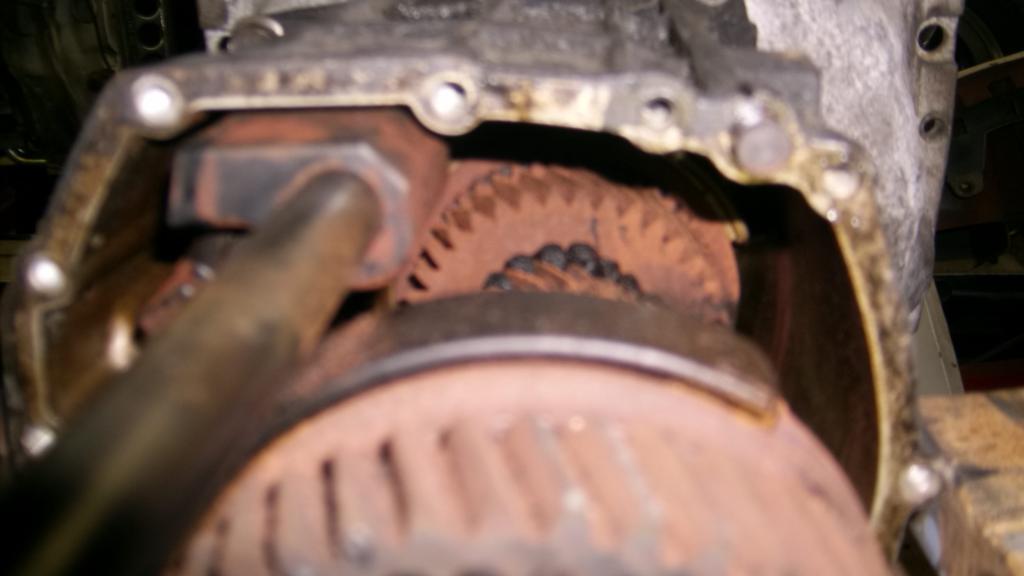
Here you can see farther into the trans the melted plastic where it oozed out from the synchros.
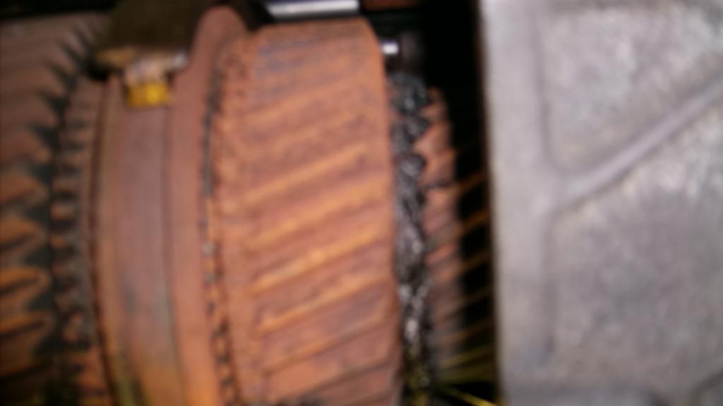
It is a real shame as there is virtually no wear on the input shaft splines and TO bearing collar and I haven't found a single mark or burr on any visible gear teeth or synchronizer.
This is all probably moot though as I picked up the trans on Saturday and the extent of the fire damage was greatly understated.
Tail housing got so hot the aluminum melted like candle wax. Totally destroyed the shifter which is a separate piece not cast into the tailhousing like tremec or t56.
Here is what I got.


can't tell if this is black or blue tag.
Once I got the the tailhousing and the rear case apart I found more problems that will probably kill the deal. The heat, while not harming any of the metal parts melted every plastic piece inside. It appears that nearly every roller bearing had a plastic cage to contain the rollers. The trans is locked up because the plastic has melted and resolidified, fusing the gears and synchros together.
This was the reverse sprag. It had a plastic cage that fused to the output shaft support bearing.

Here you can see farther into the trans the melted plastic where it oozed out from the synchros.


It is a real shame as there is virtually no wear on the input shaft splines and TO bearing collar and I haven't found a single mark or burr on any visible gear teeth or synchronizer.
Joined: Sep 1999
Posts: 4,353
Likes: 308
From: NJ
Car: 92 Firebird
Engine: 4.8 LR4
Transmission: T56
Axle/Gears: 3.45 9 Bolt
Re: Home brew road racer
WOW, that's a lot of heat!
Being the tail housing is damaged, it may have affected the temper on the gears too. IMO, that trans is scrap weight
Being the tail housing is damaged, it may have affected the temper on the gears too. IMO, that trans is scrap weight
Thread Starter
Senior Member
Joined: Aug 2007
Posts: 682
Likes: 45
Re: Home brew road racer
Ed thanks for following my insanity. Hope it wasn't to boring. I am really hoping to get this thing back on the ground and running by this summer.
Thread Starter
Senior Member
Joined: Aug 2007
Posts: 682
Likes: 45
Re: Home brew road racer
Everyone I have talked to says run away from this deal, so I am returning it back to my friend.
In searching out opinions I called a Cleveland based corvette shop that just happens to be in the middle of a trans upgrade on a customer's car. They are taking out a richmond ROD 6 speed to put in a TKO 600. I am trying to negotiate a deal for the ROD complete with Lakewood bell and spec 2 clutch.
Thread Starter
Senior Member
Joined: Aug 2007
Posts: 682
Likes: 45
Re: Home brew road racer
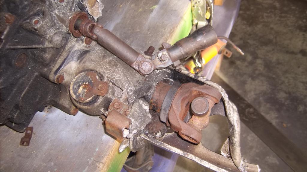
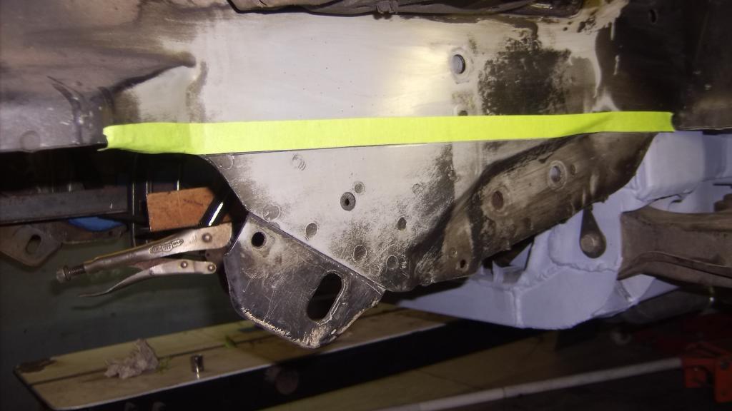
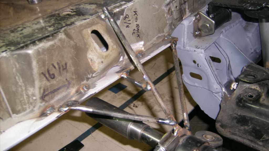
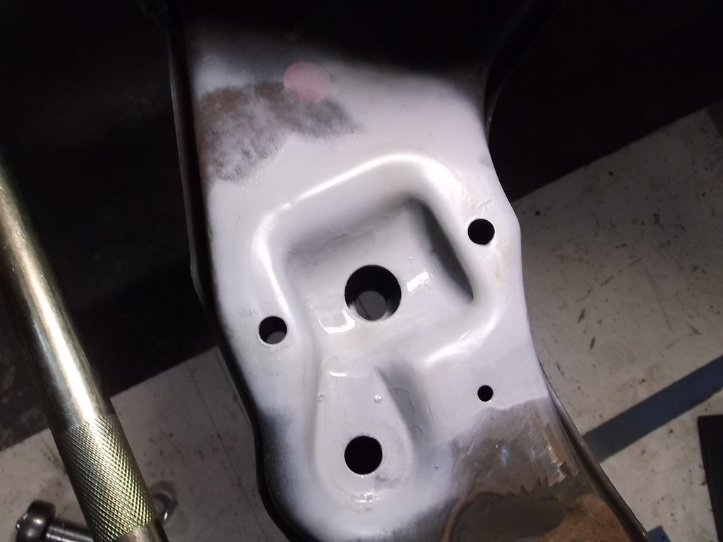
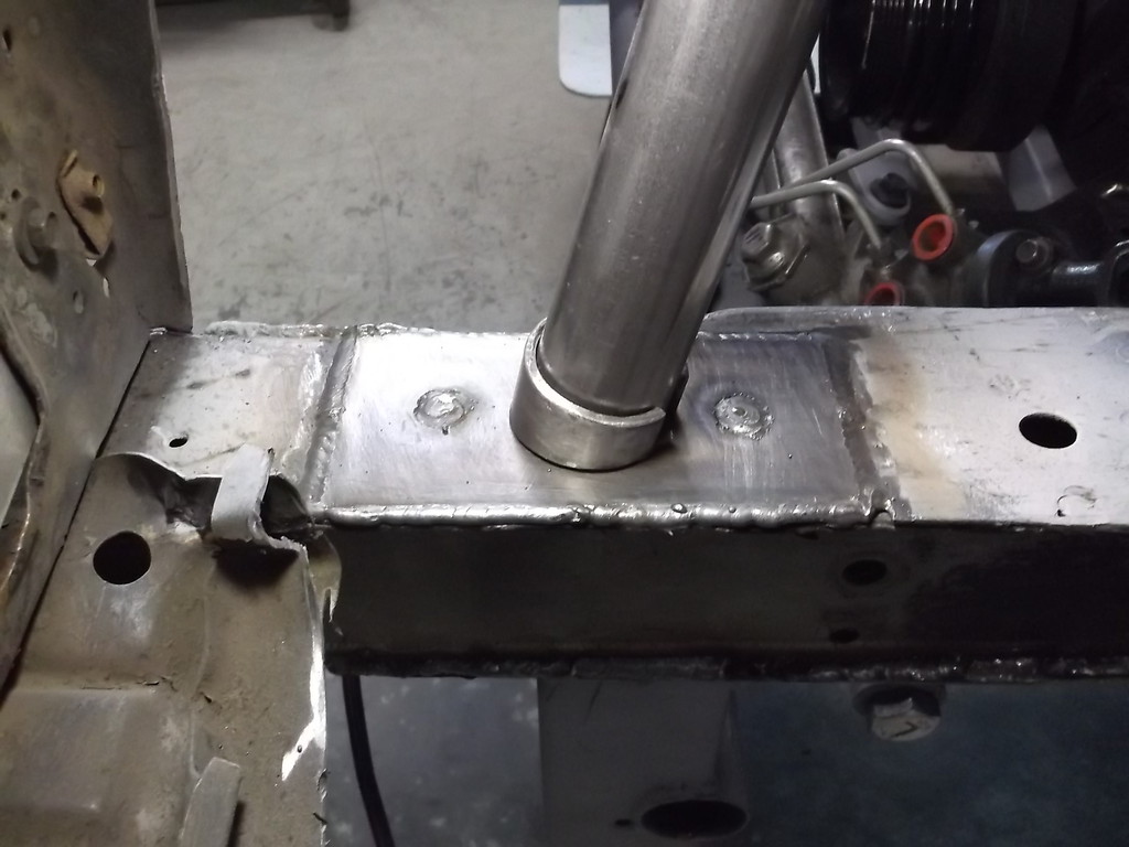
It has reached the point that I need to cut the front frame rails in order to mount the rack. I wanted to give the rack about 1" clearance as it passes under the frame. I marked the frame and projected a line using a n 18" level, and cut the bottoms of the rails off with a cutoff wheel. The bottom of the rails will be capped off with 3/16 plate. This will provide a strong mounting surface for the 2 x .120 wall tubing crossmember that the rack will mount to and that will also serve as the mount for the splined sway bar.


Thread Starter
Senior Member
Joined: Aug 2007
Posts: 682
Likes: 45
Re: Home brew road racer
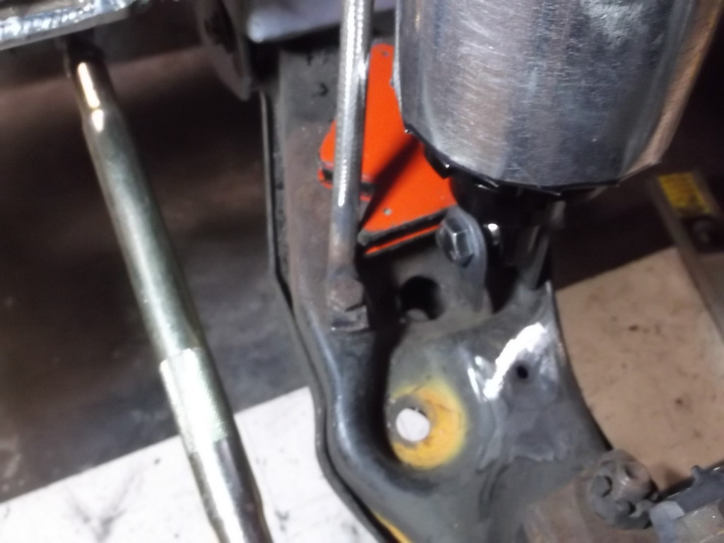
Looking at those last pictures you can see why the rails crack at the steering box. The rails are about 1/16 thick steel and have no lateral bracing past the stock k-member other than the bumper crash bar. A wonder bar is a must for any Ax or RR endeavor.

Thread Starter
Senior Member
Joined: Aug 2007
Posts: 682
Likes: 45
Thread Starter
Senior Member
Joined: Aug 2007
Posts: 682
Likes: 45
Re: Home brew road racer
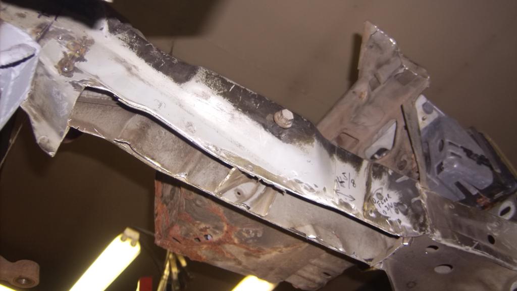
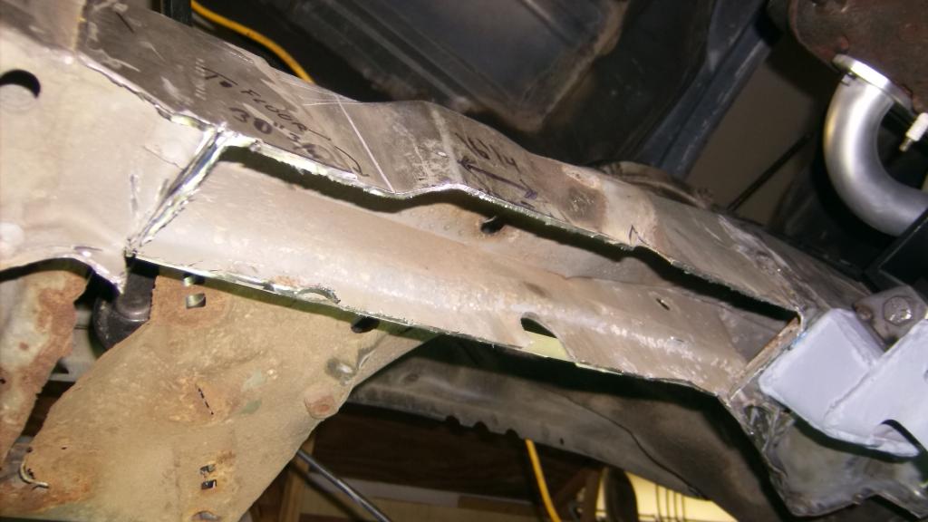
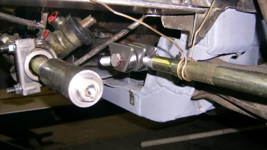
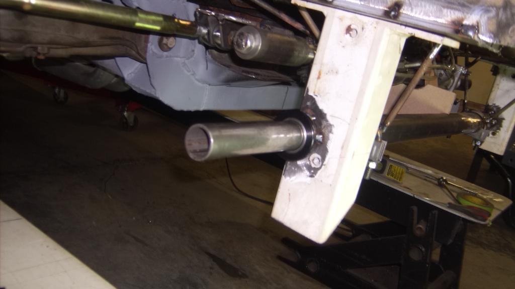
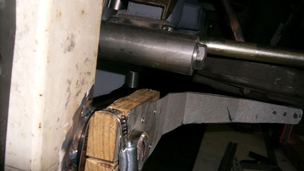
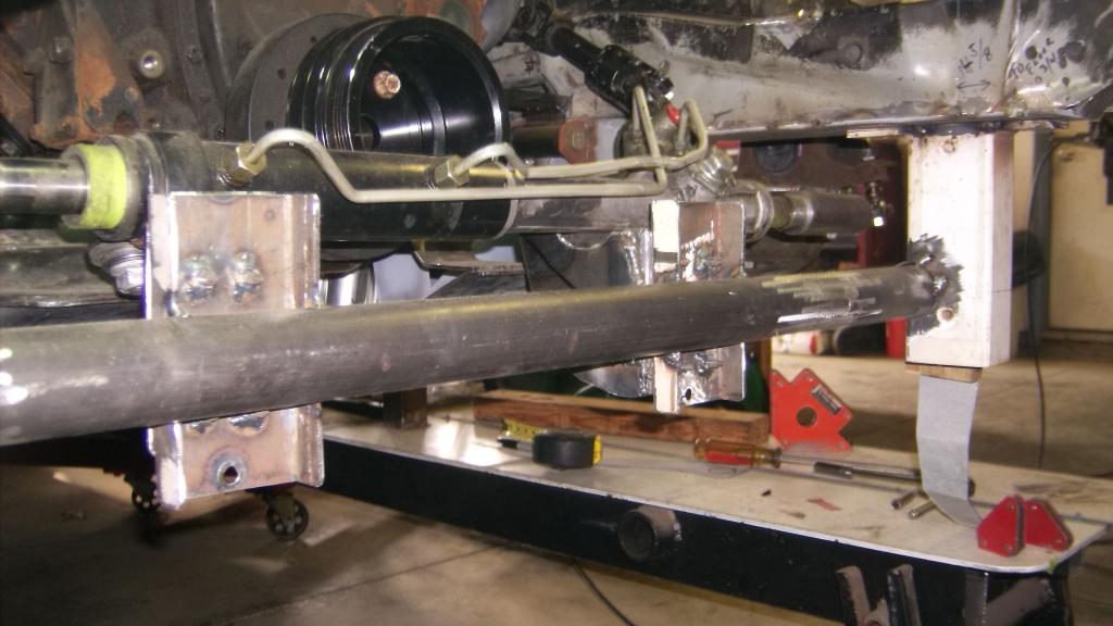
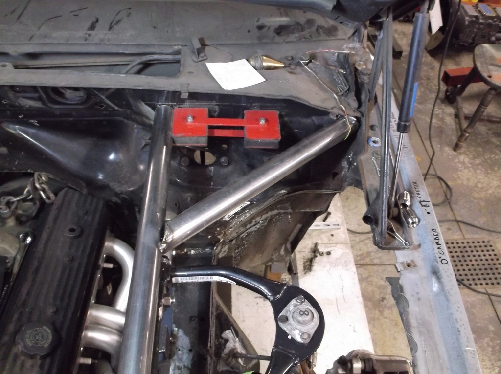
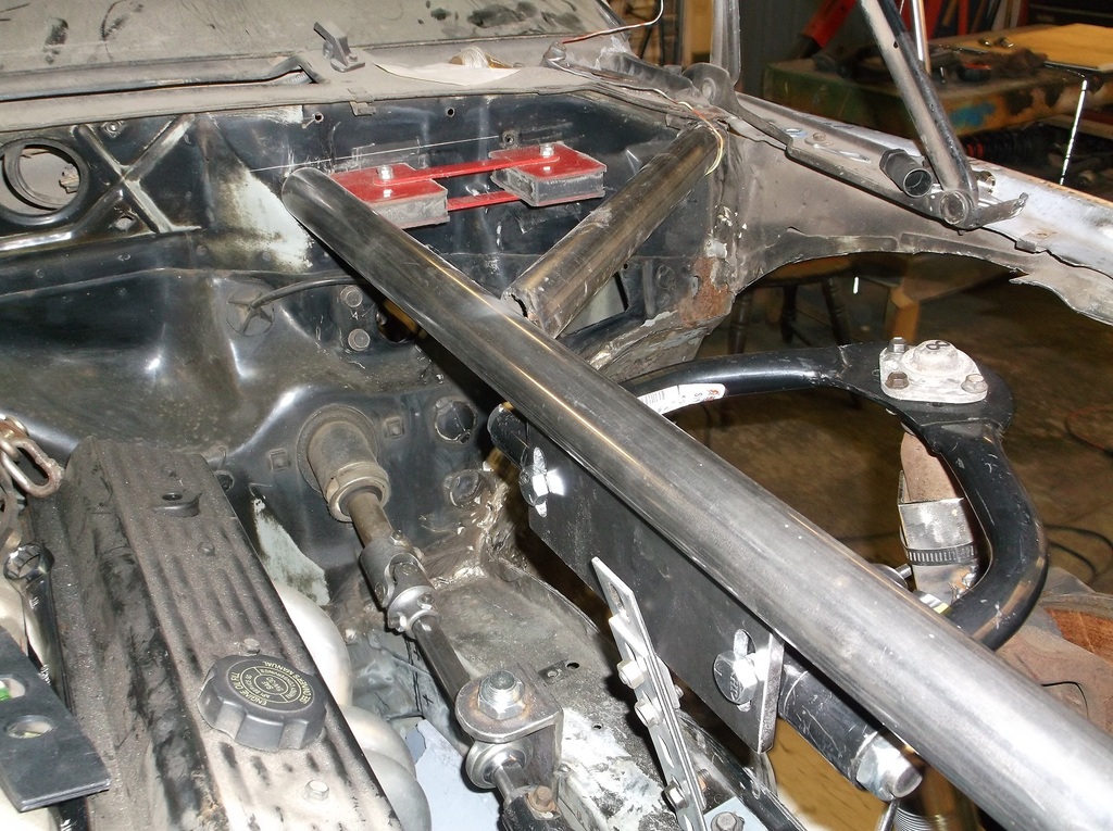
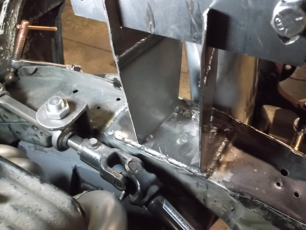
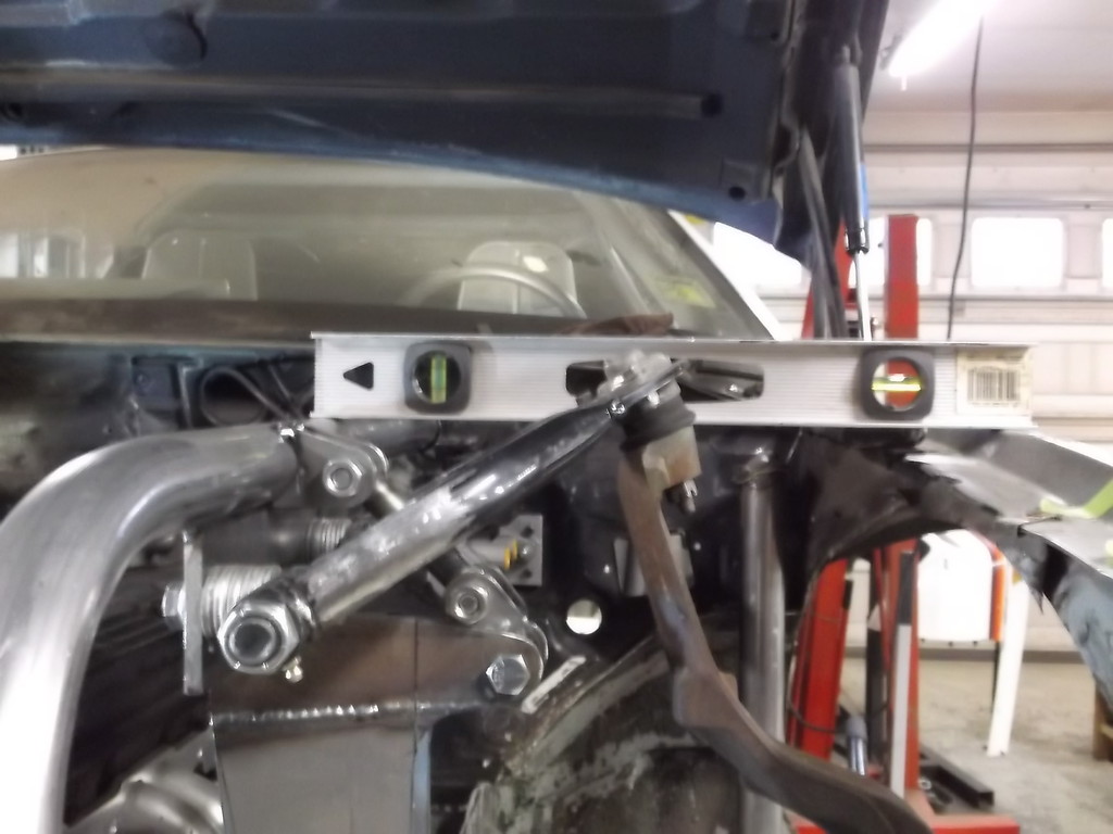
I boxed in the bottom of the rails with 3/16 plate. I took some time to make sure they were both parallel to the ground and at the same height. With those tacked in place I remounted the rack as before. This gets it in place but the angle iron and clamps get in the way of fabbing up a permanent mount. I needed a way of suspending it in place but not blocking access to the factory mounts and also allow for some rotation of the rack to get the best steering input shaft angle.
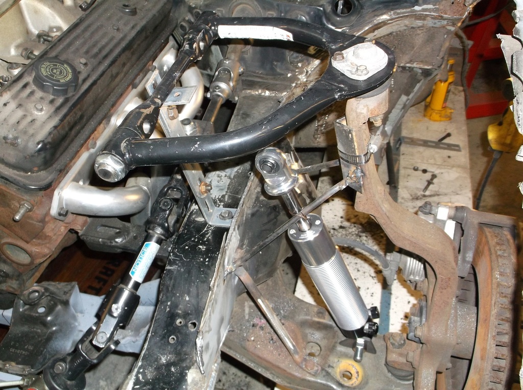
As it turns out the ends of the rack body are 2" diameter so with a couple of muffler clamps I came up with this.
I tried to triangulate the braces to prevent any movement. The rod used is from the two cross braces from in front of the radiator.
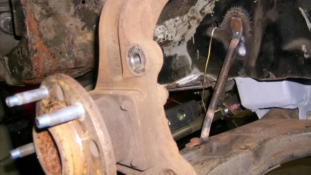
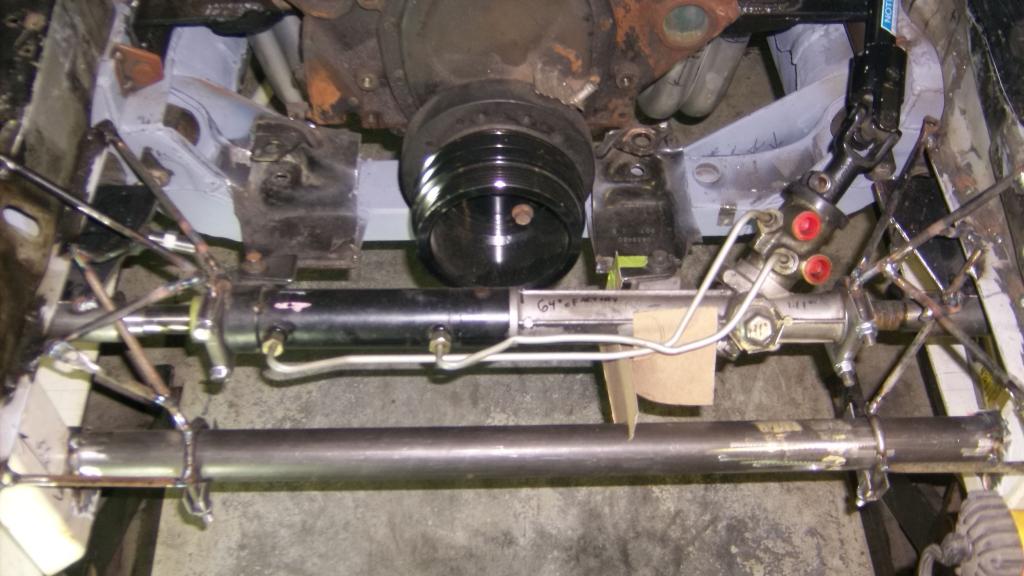
With the rack in place I hung the left side tie rod and set the height with a bubble level.
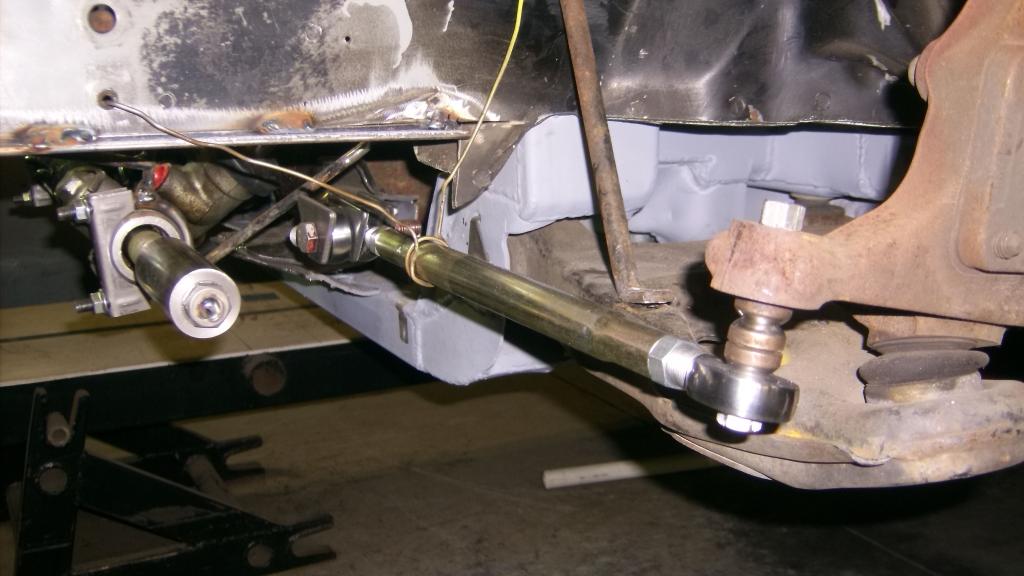
Double checking everything I discovered that the rack centerline is about 1/2" lower than the tie rod. I will have to reposition the rack. Oh well better I caught it now.
I have run into a slight delay with the rack mount. The rack will mount to a tubular crossmember that will also hold the splined front sway bar. I thought I could just go down to my local weld shop and get a piece of 2 x .120 wall tubing but after spending 1/2 hour searching with the owner we couldn't come up with a piece. I will have to order in the tube and bearings for the sway bar from Keyser/Port City through Summit Racing. It should be arrive with in a couple weeks.
As it turns out the ends of the rack body are 2" diameter so with a couple of muffler clamps I came up with this.

I tried to triangulate the braces to prevent any movement. The rod used is from the two cross braces from in front of the radiator.

With the rack in place I hung the left side tie rod and set the height with a bubble level.

Double checking everything I discovered that the rack centerline is about 1/2" lower than the tie rod. I will have to reposition the rack. Oh well better I caught it now.

I have run into a slight delay with the rack mount. The rack will mount to a tubular crossmember that will also hold the splined front sway bar. I thought I could just go down to my local weld shop and get a piece of 2 x .120 wall tubing but after spending 1/2 hour searching with the owner we couldn't come up with a piece. I will have to order in the tube and bearings for the sway bar from Keyser/Port City through Summit Racing. It should be arrive with in a couple weeks.
Senior Member

Joined: Feb 2003
Posts: 644
Likes: 0
From: Fleming Island, FL
Car: 1992 Formula 350
Engine: 5.7 L98
Transmission: 700R4
Re: Home brew road racer
Just found this thread. You have some talent there. I look forward to your progress. great job and good luck
Thread Starter
Senior Member
Joined: Aug 2007
Posts: 682
Likes: 45
Re: Home brew road racer
Thanks for looking it over. As for talent, not to sure. its been a lot of learn as you go kind of deal. Some days there is more head scratching and sketching done than actual fabrication. This rack relocation really put me t the test!
Thread Starter
Senior Member
Joined: Aug 2007
Posts: 682
Likes: 45
Re: Home brew road racer
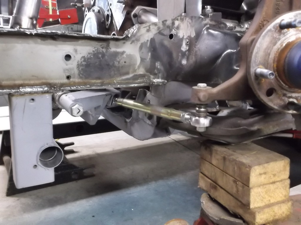
In order to get this steering sorted out I have to be able to have the spindles swing through their arc, something they can't do being bolted to my positioning stands. To hold the lower a-arms in place I used brackets that I kept from my salvaged C1500. This holds the a-arm secure and won't interfere with wheel movement or shock mounting.
Next I needed to secure the top of the spindle that would hold it at the base line caster/camber specs (+6* caster/ 0* camber). Some 1/8" slotted strap fastened to the forward two slots in the top of the fenderwell did the job.
Next I cut out the two extension brackets that will connect the rack to the tie rods. It is 3/16 plate. Tack welded the mounting tabs.
After taking great care to make sure both tie rods were parallel to the ground and spaced away from the k-member the same distance, I tack welded the extension brackets to the rack adapters.

It steers!!!!!!!!!!!!!!!!!!!!!!!!!!!!!!!!!!!
Turning the rack input shaft by hand I get full travel and no binding what so ever. I took some time and rotated the rack to lean the input shaft back as far as I could without having the left extension plate crash into the spool valve housing.
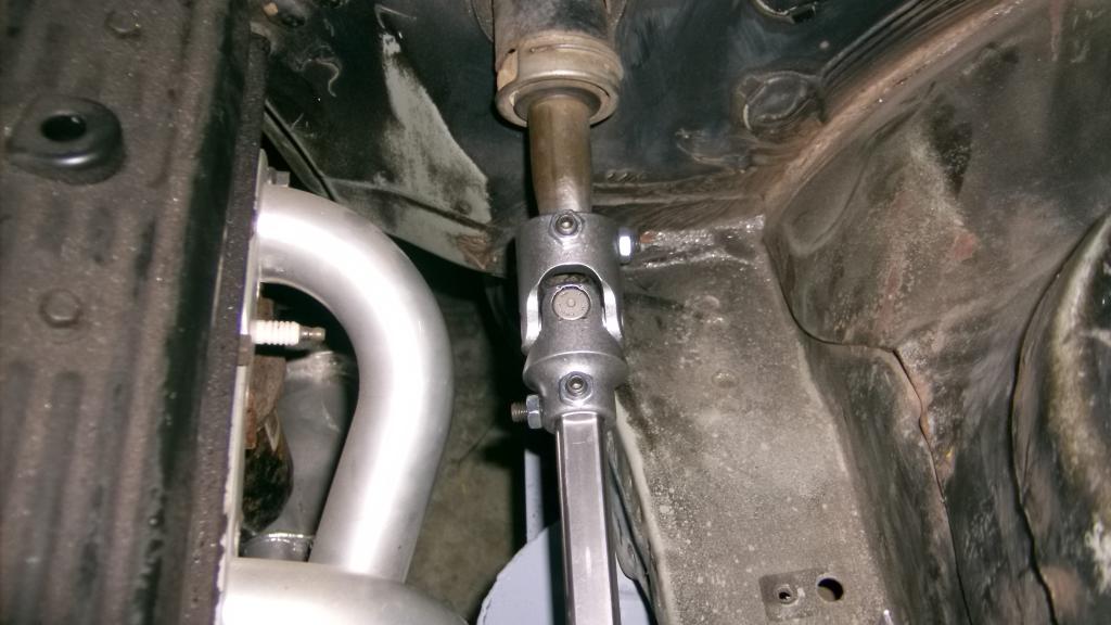
With the rack position set I set about hooking it back up to the steering column. It was very convenient that GM used the same 1"DD shaft size for the 3rd and 4th gen cars. I was able to cut off the rag joint from the 3rd gen shaft and slide it right into the 4th gen u-joint.
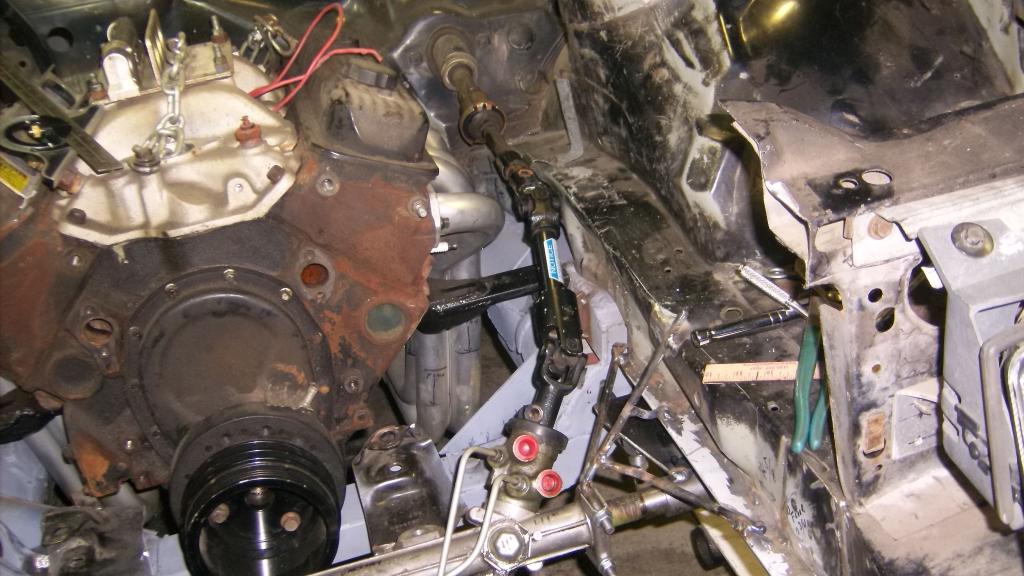
With the steering shaft hooked up I initially had some binding as the angle of the u-joint at the rack was at to sharp an angle. I raised the steering shaft where it ran along the frame about an inch and that seems to have fixed the problem. I will probably replace the factory coupler at the bottom of the steering column with a u-joint and add a bearing support to hold the shaft in place.
This just might work after all!!!!!!!!!!!


Next I needed to secure the top of the spindle that would hold it at the base line caster/camber specs (+6* caster/ 0* camber). Some 1/8" slotted strap fastened to the forward two slots in the top of the fenderwell did the job.

Next I cut out the two extension brackets that will connect the rack to the tie rods. It is 3/16 plate. Tack welded the mounting tabs.

After taking great care to make sure both tie rods were parallel to the ground and spaced away from the k-member the same distance, I tack welded the extension brackets to the rack adapters.


It steers!!!!!!!!!!!!!!!!!!!!!!!!!!!!!!!!!!!
Turning the rack input shaft by hand I get full travel and no binding what so ever. I took some time and rotated the rack to lean the input shaft back as far as I could without having the left extension plate crash into the spool valve housing.
With the rack position set I set about hooking it back up to the steering column. It was very convenient that GM used the same 1"DD shaft size for the 3rd and 4th gen cars. I was able to cut off the rag joint from the 3rd gen shaft and slide it right into the 4th gen u-joint.


With the steering shaft hooked up I initially had some binding as the angle of the u-joint at the rack was at to sharp an angle. I raised the steering shaft where it ran along the frame about an inch and that seems to have fixed the problem. I will probably replace the factory coupler at the bottom of the steering column with a u-joint and add a bearing support to hold the shaft in place.
This just might work after all!!!!!!!!!!!
Thread Starter
Senior Member
Joined: Aug 2007
Posts: 682
Likes: 45
Re: Home brew road racer
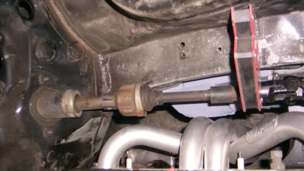
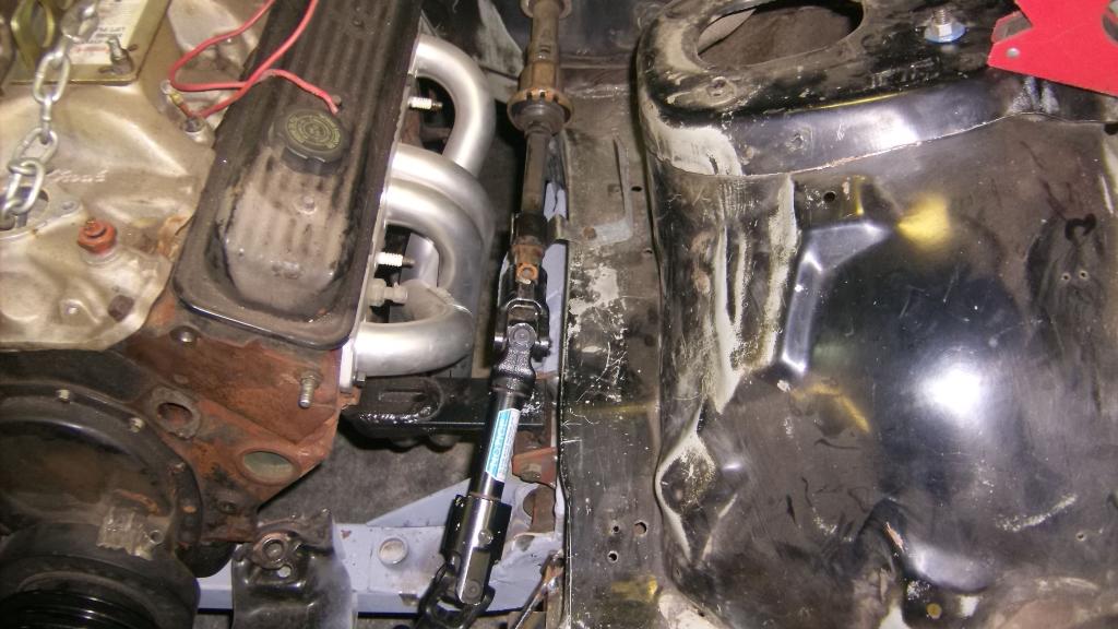
I replaced the stock steering coupler with a borgenson u-joint 1"DD to 3/4"DD and a 9 1/2" length of 3/4DD steel shaft. I forgot to get the support bearing so I will have to mount that later.


Thread Starter
Senior Member
Joined: Aug 2007
Posts: 682
Likes: 45
Re: Home brew road racer
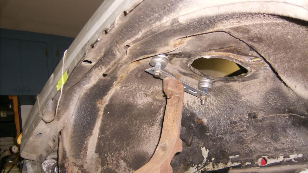
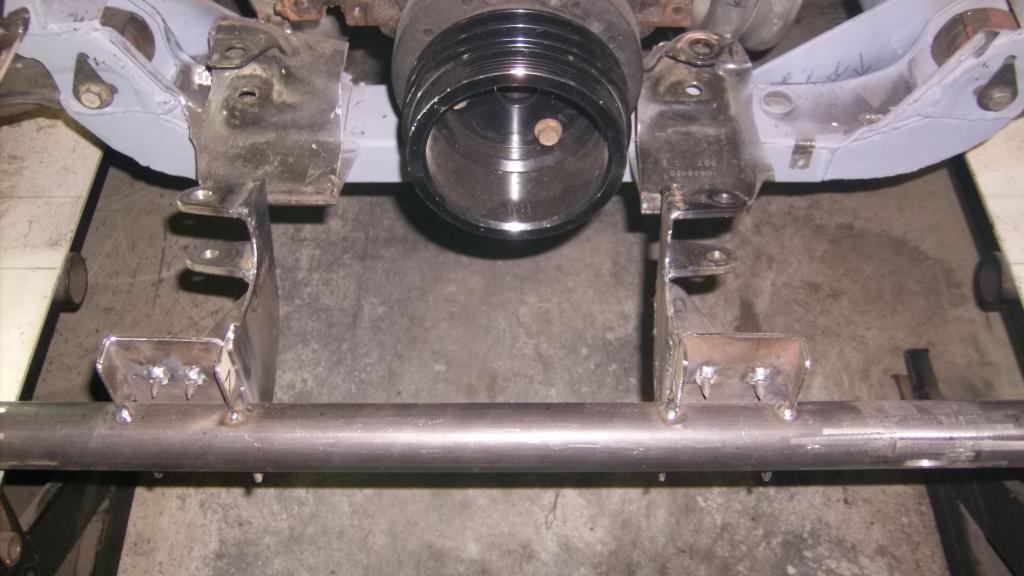
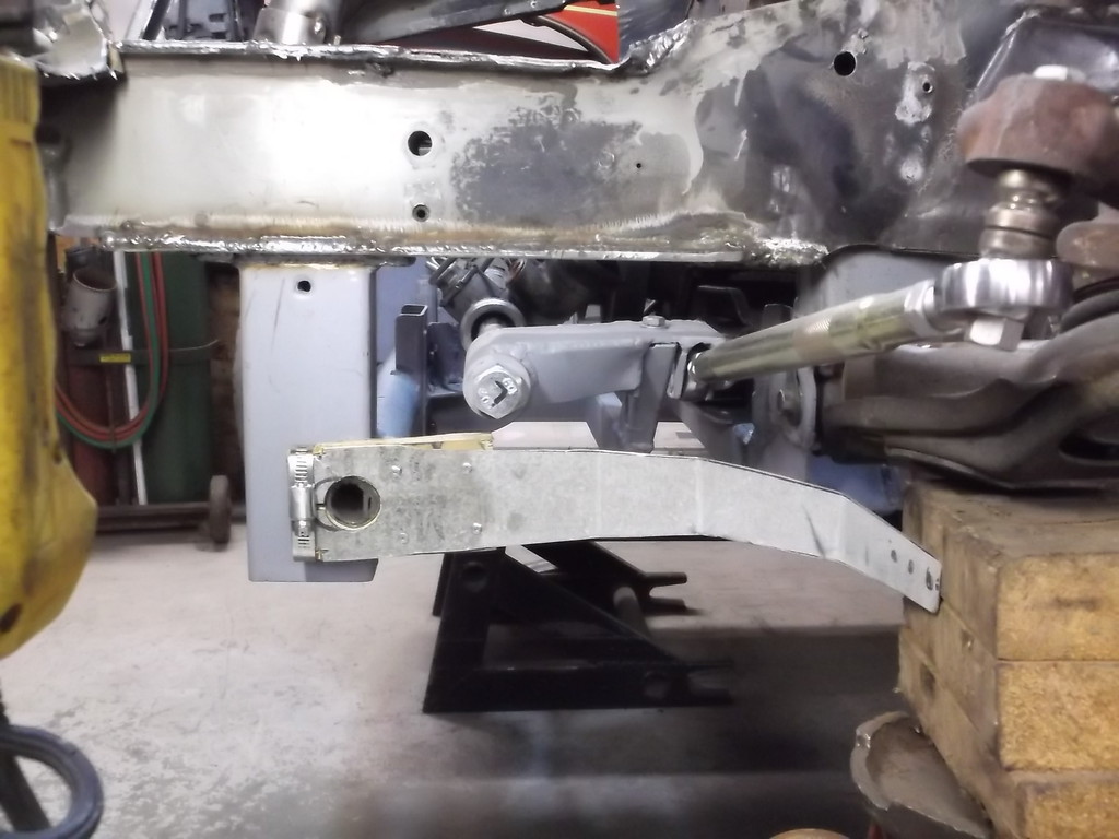
The steering rack will mount to the tubular crossmember that will hold the splined sway bar. I bought the mount kit from Keyser/Port City and matching bearings for a 1 1/4 diameter bar. I was really disappointed with the kit. The bearings measure 1.750od but the tubing is thin wall 2"od and the bearings fit very loose. Also the supplied tubing to mount it to the frame was just 1 1/4 x .060 square. Not to stout for a crossmember.
I ended up mounting the tube with the supplied parts to get it into position then replaced the 1 1/4 square with 2x3 x .125 and then cut out the tube between the mounts and replaced it with 1 3/4 x 1.20 tubing.
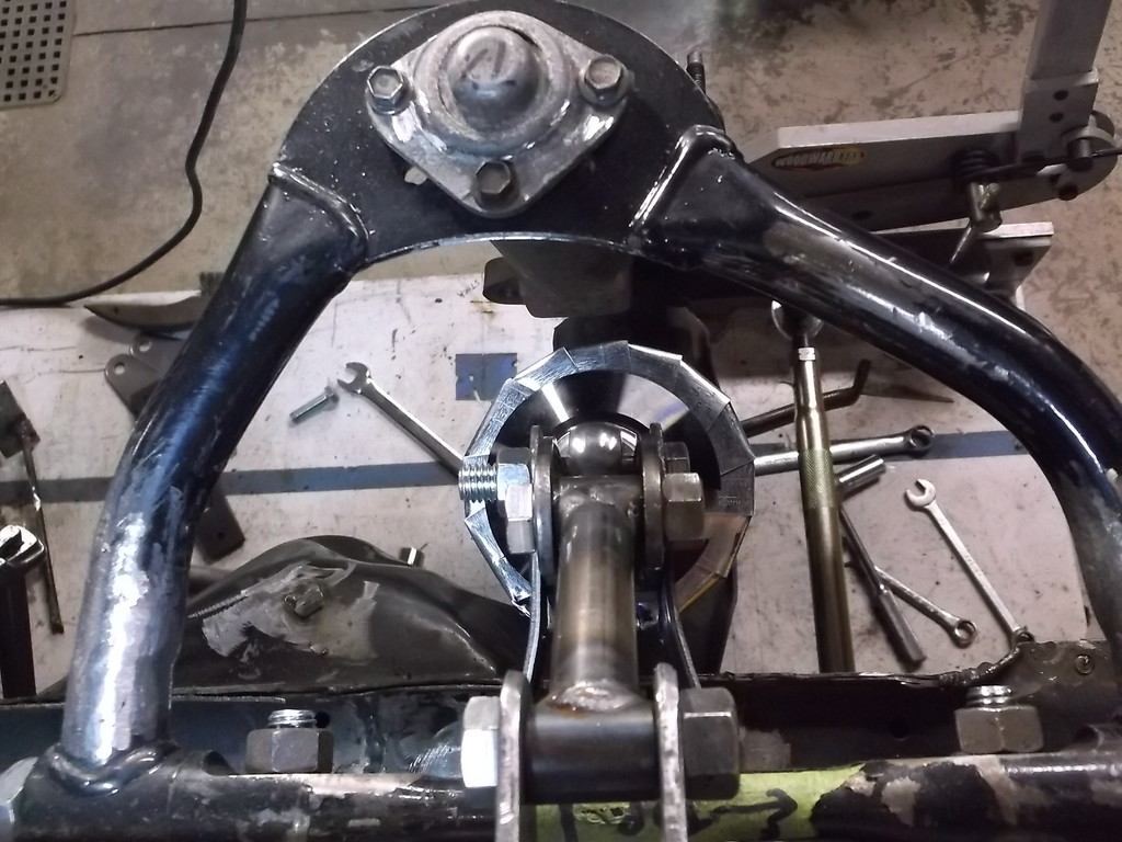
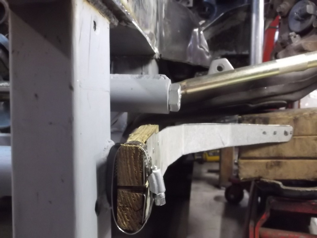
I mocked up the sway bar arms using scrap wood and sheet metal to simulate a 17" long arm. A length of 1 1/4 tubing subbed for the sway bar.
At full left turn
Because the splined sway bars are made to a standard 37 1/2" length the arms fall under my rack extensions. The extensions will be shortened by an inch both sides but I will have to keep an eye on possible interference. I can probably gain more clearance with a 30 degree offset arm. I will fab one of those and see if it helps.
I ended up mounting the tube with the supplied parts to get it into position then replaced the 1 1/4 square with 2x3 x .125 and then cut out the tube between the mounts and replaced it with 1 3/4 x 1.20 tubing.


I mocked up the sway bar arms using scrap wood and sheet metal to simulate a 17" long arm. A length of 1 1/4 tubing subbed for the sway bar.

At full left turn


Because the splined sway bars are made to a standard 37 1/2" length the arms fall under my rack extensions. The extensions will be shortened by an inch both sides but I will have to keep an eye on possible interference. I can probably gain more clearance with a 30 degree offset arm. I will fab one of those and see if it helps.
Thread Starter
Senior Member
Joined: Aug 2007
Posts: 682
Likes: 45
Re: Home brew road racer
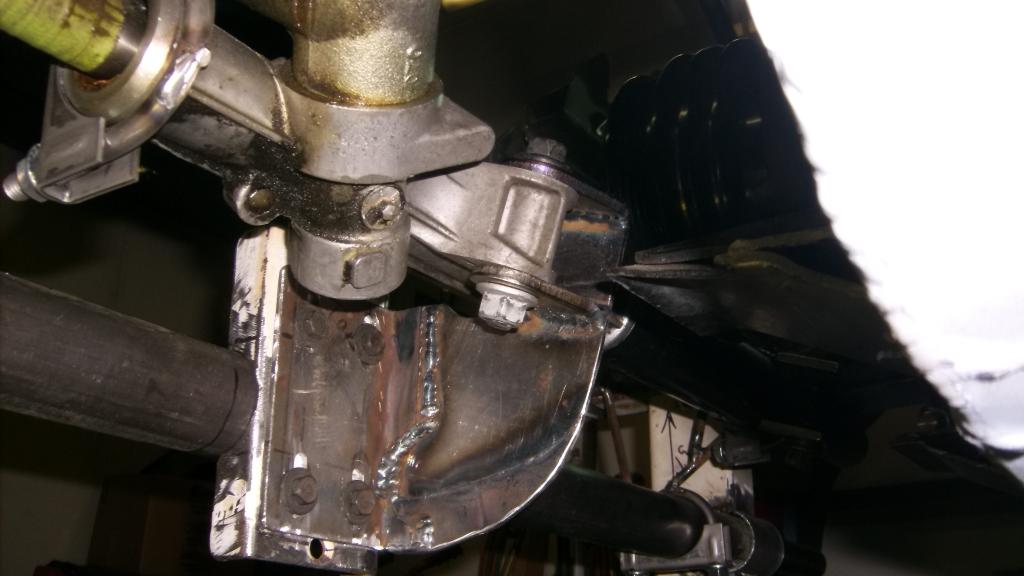
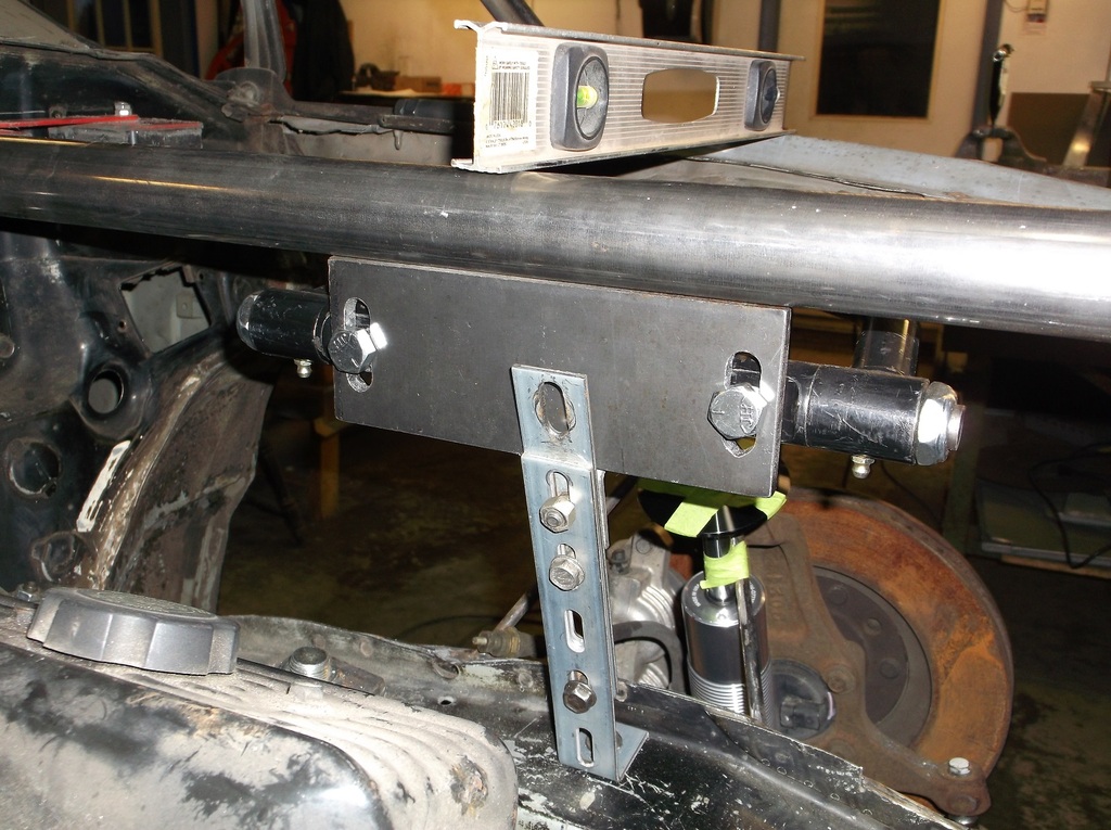
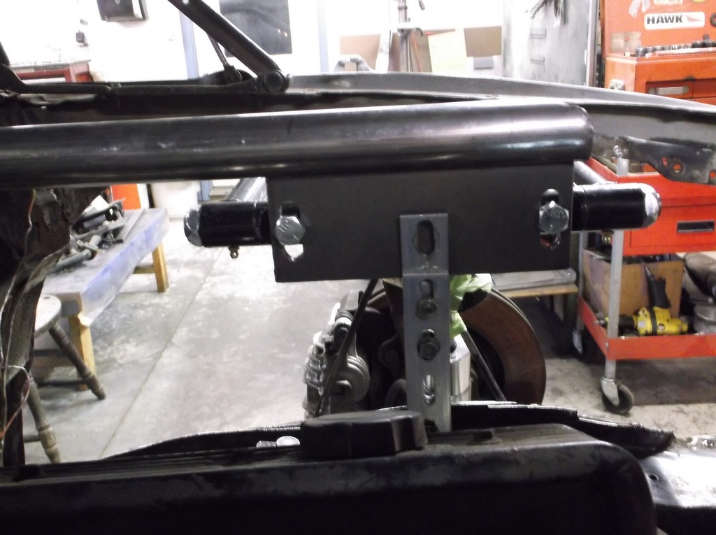
Here are a couple pics of the bracket to mount the rack to the crossmember. The rack is rotated rearward 20 degrees to better align the steering input shaft. For whatever reason I made my mounting brackets at the same 20 degree angle.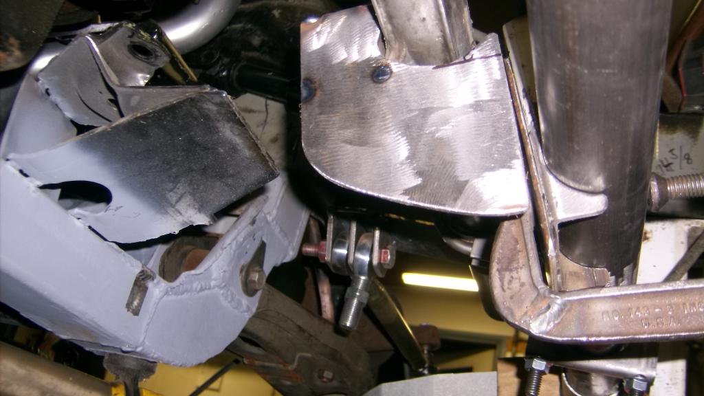
It was going well until I remembered that the mounts have to be vertical so I can adjust the rack height up and down to adjust bump steer. Oh well, 3 hrs wasted but better caught now as nothing was welded in yet.


It was going well until I remembered that the mounts have to be vertical so I can adjust the rack height up and down to adjust bump steer. Oh well, 3 hrs wasted but better caught now as nothing was welded in yet.
Thread Starter
Senior Member
Joined: Aug 2007
Posts: 682
Likes: 45
Re: Home brew road racer
I would like to give a big thank you to TGO member Propaintball for offering me a TKO 600 at a very reasonable price for the project. It bolted up to my Lakewood bellhousing and is dimensionally the same as the 700R4 so trans mount and driveshaft work with no modifications.

Thread Starter
Senior Member
Joined: Aug 2007
Posts: 682
Likes: 45
Re: Home brew road racer
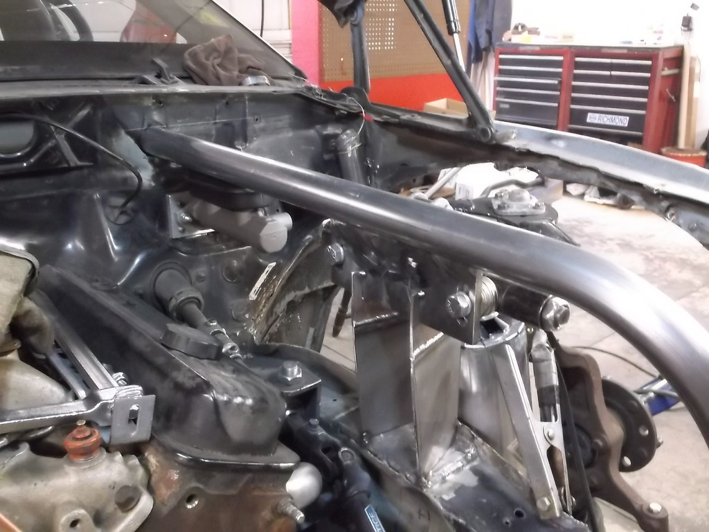
Moving on with the steering rack. Mounts were made and all the temporary bracing was removed. That really cleaned up the area in front of the engine.
Vertical stiffness was good but lateral was weak so I added some bracing and tied the two together. Seems to have cured the flex problem.


Vertical stiffness was good but lateral was weak so I added some bracing and tied the two together. Seems to have cured the flex problem.

Thread Starter
Senior Member
Joined: Aug 2007
Posts: 682
Likes: 45
Re: Home brew road racer
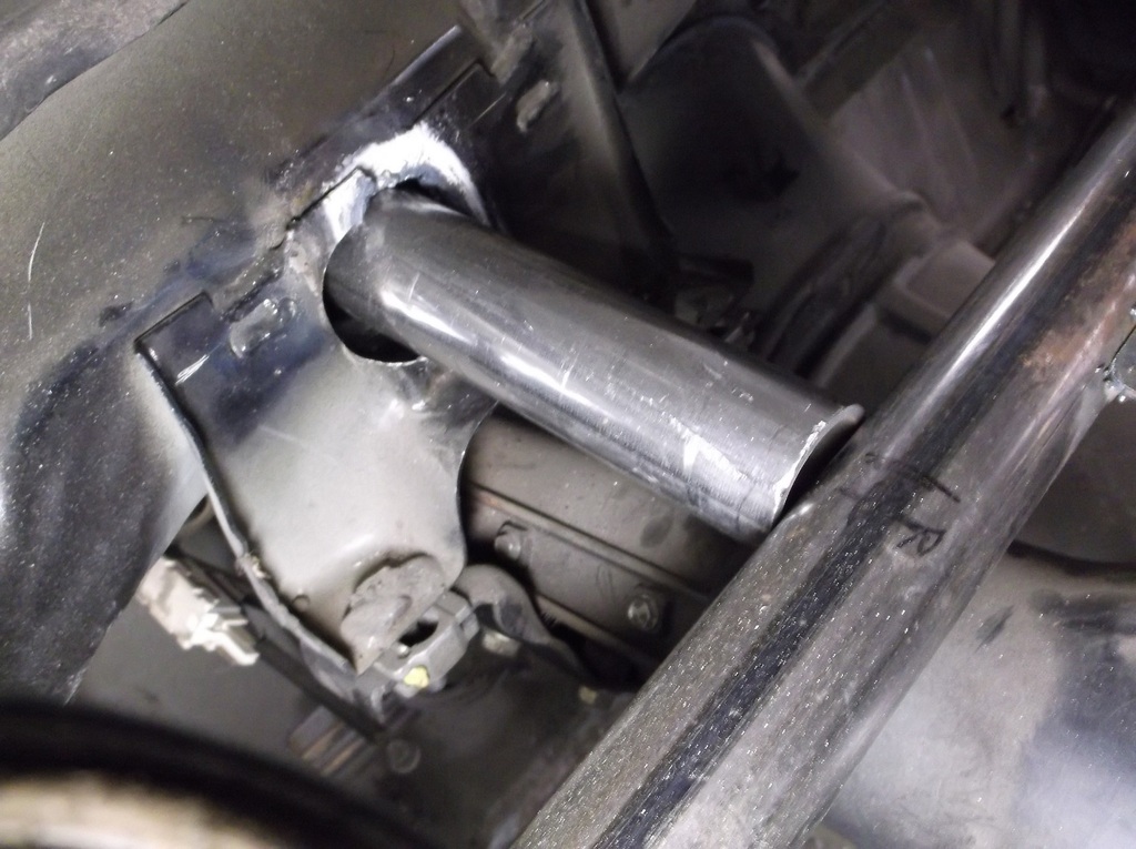
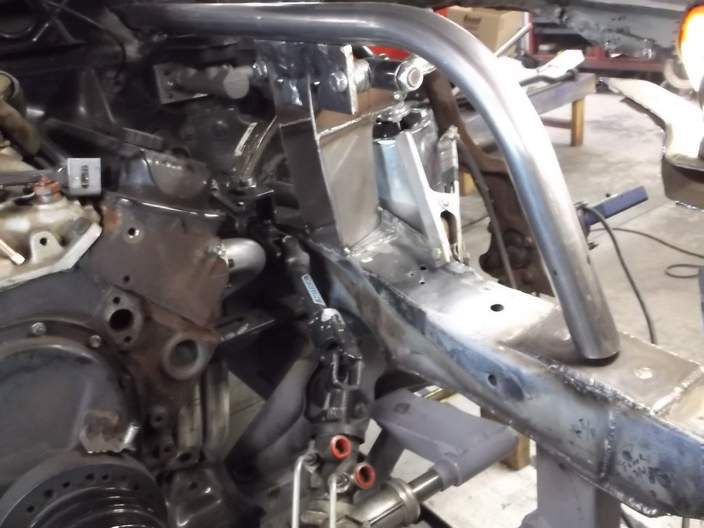
With the steering and suspension swap looking like it is going to work I took a leap of faith and cut the front half of the wheel well out and mounted a tire to the spindle. With running the rack lock to lock there seems to be plenty of clearance between frame, steering linkage and sway bar. To my surprise the tire almost clears the "bump" for the factory coil spring. I had thought I would have to cut the whole thing out and replate the frame but I may leave it for strength and just do a minor clearance mod.
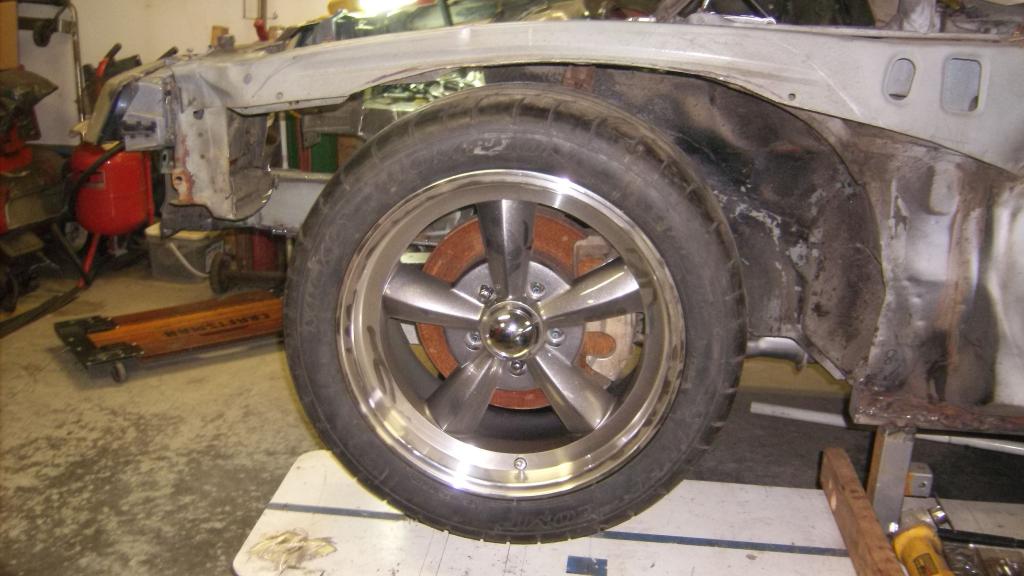
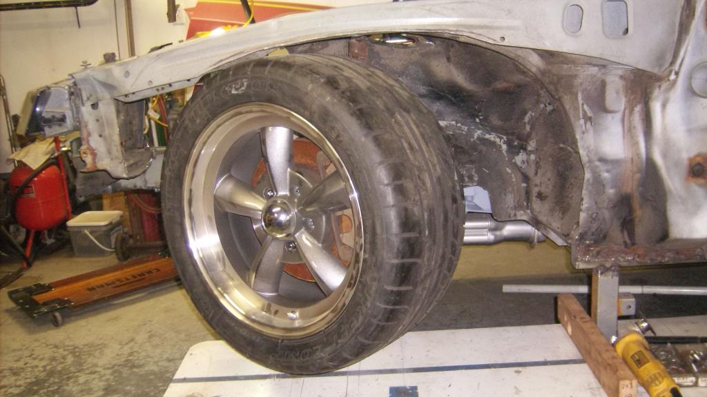
To get 3" of up travel I will have to remove the entire Upper frame structure above the wheel well. I will be making new wheel well from fiberglass and the fender will mount directly to the top of it.
Sway bar clearance.


To get 3" of up travel I will have to remove the entire Upper frame structure above the wheel well. I will be making new wheel well from fiberglass and the fender will mount directly to the top of it.

Sway bar clearance.


Member
iTrader: (1)
Joined: Jul 2013
Posts: 123
Likes: 0
From: Pensacola FL
Car: 1986 Camaro Sport Coupe (Part Out)
Engine: 2.8 MPFI V6
Transmission: 700R4 Automatic 4 speed
Axle/Gears: 3.42 Open With Drum Brakes
Re: Home brew road racer
[QUOTE=83RDRACR;5882760]I would like to give a big thank you to TGO member Propaintball for offering me a TKO 600 at a very reasonable price for the project. It bolted up to my Lakewood bellhousing and is dimensionally the same as the 700R4 so trans mount and driveshaft work with no modifications.
Any details on the internal workings of the TKO 600? Is it a 5 or 6 speed? Are they expensive for a new one?
It's cool knowing that it was pretty much a direct bolt in replacement for the 700R4. Sounds like it would make a nice alternative for a T-5 or T-56.
Any details on the internal workings of the TKO 600? Is it a 5 or 6 speed? Are they expensive for a new one?
It's cool knowing that it was pretty much a direct bolt in replacement for the 700R4. Sounds like it would make a nice alternative for a T-5 or T-56.
Thread Starter
Senior Member
Joined: Aug 2007
Posts: 682
Likes: 45
Re: Home brew road racer
[QUOTE='86 Sport Coupe;5882788]
Sport Coupe, thanks for following along.
The TKO 600 is a 5 speed with 5th gear being overdrive. Tremec offers 2 versions, a road race version where OD is .82 to 1 and a "cruiser" version with a .60 to 1 OD ratio. Everything else is the same between the two versions. The 600 refers to the trans rated torque capacity of 600lbs/ft. There is also a TKO 500 of the same dimensions, but with different gear ratios rated at 500lbs/ft.
Both the 500 and 600 versions mimic the major dimensions of the 700r4 and T5 as far as trans mount position and overall length and even have mounting provisions for the torque arm. They do require a different trans yoke, 32 spline same as a TH400, where as the 700R4 and T5 use a 27 spline like a TH350.
The T56 is a 6 speed trans with a double overdrive so it is like getting both versions of the TKO 600 in one unit. It is dimensionally different both in length and trans mount location. I don't have the specs in front of me but I believe both dimensions are longer than the 700R4. It requires a special crossmember and a shorter drive shaft.
I would like to give a big thank you to TGO member Propaintball for offering me a TKO 600 at a very reasonable price for the project. It bolted up to my Lakewood bellhousing and is dimensionally the same as the 700R4 so trans mount and driveshaft work with no modifications.
Any details on the internal workings of the TKO 600? Is it a 5 or 6 speed? Are they expensive for a new one?
It's cool knowing that it was pretty much a direct bolt in replacement for the 700R4. Sounds like it would make a nice alternative for a T-5 or T-56.
Any details on the internal workings of the TKO 600? Is it a 5 or 6 speed? Are they expensive for a new one?
It's cool knowing that it was pretty much a direct bolt in replacement for the 700R4. Sounds like it would make a nice alternative for a T-5 or T-56.
Sport Coupe, thanks for following along.
The TKO 600 is a 5 speed with 5th gear being overdrive. Tremec offers 2 versions, a road race version where OD is .82 to 1 and a "cruiser" version with a .60 to 1 OD ratio. Everything else is the same between the two versions. The 600 refers to the trans rated torque capacity of 600lbs/ft. There is also a TKO 500 of the same dimensions, but with different gear ratios rated at 500lbs/ft.
Both the 500 and 600 versions mimic the major dimensions of the 700r4 and T5 as far as trans mount position and overall length and even have mounting provisions for the torque arm. They do require a different trans yoke, 32 spline same as a TH400, where as the 700R4 and T5 use a 27 spline like a TH350.
The T56 is a 6 speed trans with a double overdrive so it is like getting both versions of the TKO 600 in one unit. It is dimensionally different both in length and trans mount location. I don't have the specs in front of me but I believe both dimensions are longer than the 700R4. It requires a special crossmember and a shorter drive shaft.
Thread Starter
Senior Member
Joined: Aug 2007
Posts: 682
Likes: 45
Re: Home brew road racer
The plans call for 1 5/8 dia. support tubes to run from the knee bar inside the car to just behind the radiator core support. they will incorporate the upper control arm mounts as well. I will be cutting the rest of the wheel wells out real soon and positioning the upper A-arm. I will have to make up a few drawings projecting the angles of the upper and lower arms and plot the front roll center.
If any member has access to one of the suspension software programs it would be great to plot these out and minimize roll center migration and bump steer. I would also like to keep the instant center above ground, I am thinking 2" to 3" would be about right.
Thread Starter
Senior Member
Joined: Aug 2007
Posts: 682
Likes: 45
Re: Home brew road racer
I spent most of last week end welding up everything that had been tacked together. While doing so I got the idea that it might be better to make my so called center link from rectangular tubing instead of the heim joints and threaded tubes. I would still have it fasten to the inner tie rods with the same thru bolt arrangement. I think it would make it stronger, less likely to flex and easier to make a rolling guide to help hold it up, taking some strain off the rack.
I only have a 3/4 gap in the rack adapters where the heim joint fit so I will have to see what is available at the weld shop. Maybe 1/2 x 1 1/2 with a welded in sleeve for the bolt to pass thru.
I only have a 3/4 gap in the rack adapters where the heim joint fit so I will have to see what is available at the weld shop. Maybe 1/2 x 1 1/2 with a welded in sleeve for the bolt to pass thru.

Member
Joined: Jan 2010
Posts: 247
Likes: 8
Re: Home brew road racer
The plans call for 1 5/8 dia. support tubes to run from the knee bar inside the car to just behind the radiator core support. they will incorporate the upper control arm mounts as well. I will be cutting the rest of the wheel wells out real soon and positioning the upper A-arm. I will have to make up a few drawings projecting the angles of the upper and lower arms and plot the front roll center.
If any member has access to one of the suspension software programs it would be great to plot these out and minimize roll center migration and bump steer. I would also like to keep the instant center above ground, I am thinking 2" to 3" would be about right.
If any member has access to one of the suspension software programs it would be great to plot these out and minimize roll center migration and bump steer. I would also like to keep the instant center above ground, I am thinking 2" to 3" would be about right.
Get with Twin_Turbo on TGO. I think he has this software and if not, he is extremely knowledgeable on suspension.
Thread Starter
Senior Member
Joined: Aug 2007
Posts: 682
Likes: 45
Re: Home brew road racer
Its been a tough month. Got sick and couldn't work on the car, DSL modem died for the 3rd time in 4 years so switched to timewarner cable and way faster, dropped my digital camera and it wouldn't turn back on so had to get a new one with way better resolution. Now after all the upgrades I cant upload my pics to photobucket. Any advice would be appreciated.
So we will resort to thumbprints. Looks like I will have to resize before I can post. All the pics are to big.
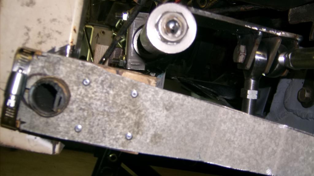
I went ahead with the rectangular tube center link. Had to cut and move a bracket to get the 1 1/2 x 3/4 tubing to fit. I got pretty **** about its mounting and added a 5/16 bolt through the top to supplement the 1/2" thru bolt. The tubing fits very tight in the brackets no play what so ever. Also ran gussets underneath to minimize any chance of flex or bending. All that is left is the guide/support rollers. Those will go in after the front accessories are mounted. Hopefully this will prevent any flex in the rack and let the car steer like a 4th gen.
So we will resort to thumbprints. Looks like I will have to resize before I can post. All the pics are to big.
I went ahead with the rectangular tube center link. Had to cut and move a bracket to get the 1 1/2 x 3/4 tubing to fit. I got pretty **** about its mounting and added a 5/16 bolt through the top to supplement the 1/2" thru bolt. The tubing fits very tight in the brackets no play what so ever. Also ran gussets underneath to minimize any chance of flex or bending. All that is left is the guide/support rollers. Those will go in after the front accessories are mounted. Hopefully this will prevent any flex in the rack and let the car steer like a 4th gen.
Thread Starter
Senior Member
Joined: Aug 2007
Posts: 682
Likes: 45
Re: Home brew road racer
Ok I got the photo thing all figured out. Not sure what good a high resolution camera is if a single pic is to large to upload. Anyway got them all resized, loaded into photobucket so here we go.
The nearly finished rack and pinion install:
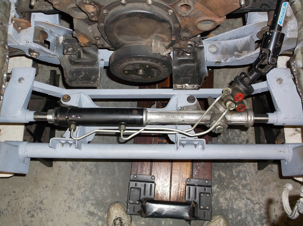
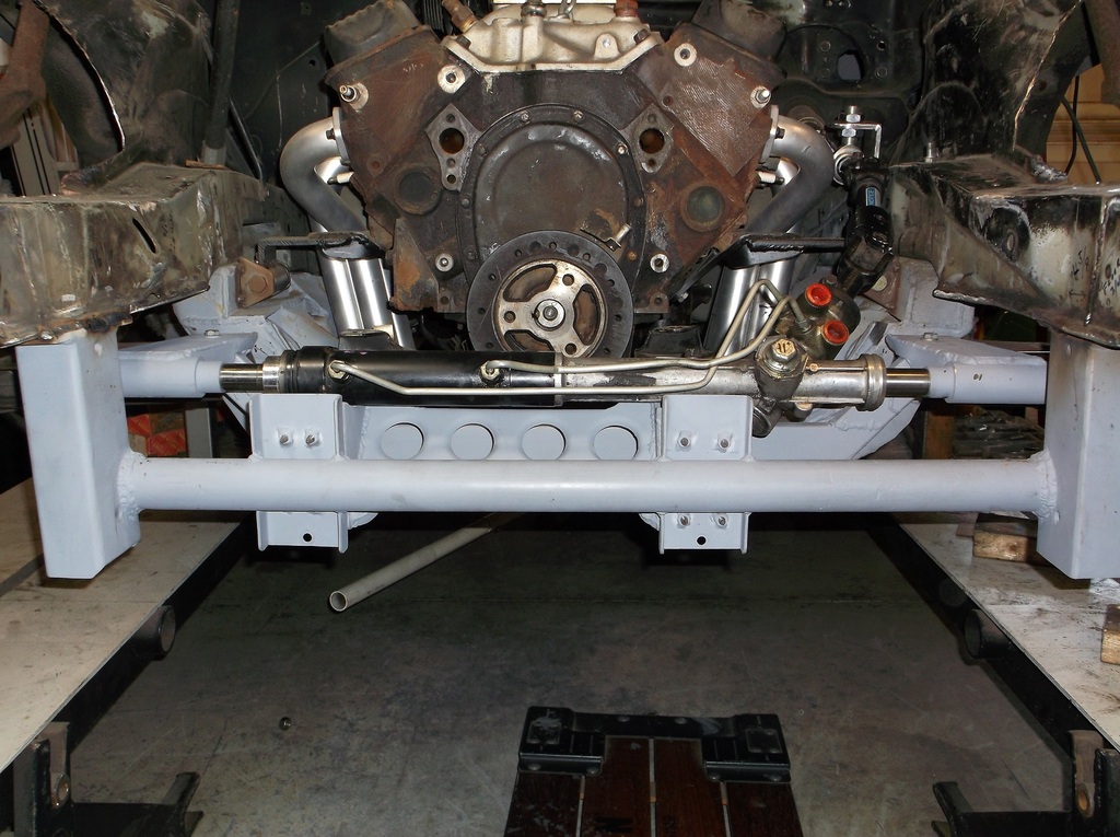
I put in all the pics so I can get as many eyes looking at this as possible. Please let me know if you see something tyhat possibly won't work. Right now I think I have this stering problem licked.
Oh one more thing. I found out that Spohn makes a bump steer kit for the 4th gen spindles. They will sell the tie rod adapter that takes the place of the outer tie rod end separately so now I won't have to drill the steering arms.
Thread Starter
Senior Member
Joined: Aug 2007
Posts: 682
Likes: 45
Re: Home brew road racer
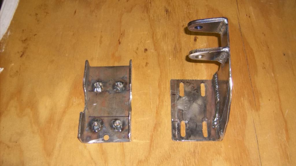
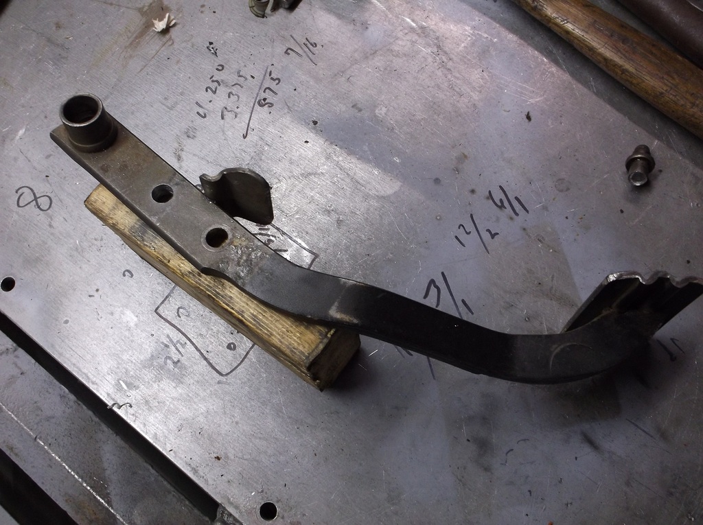
Time to get the upper A-arm in place. I started with the stock arm and mount. The arm is kind of flimsy and the mount is really big and heavy. In the 4th gen this supported the weight of the front end as it was the upper mount for the very long and heavy coil over shock that they used.
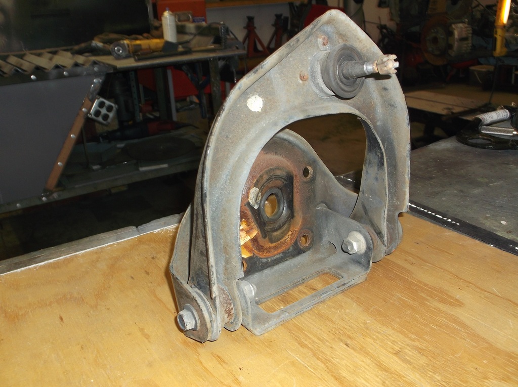
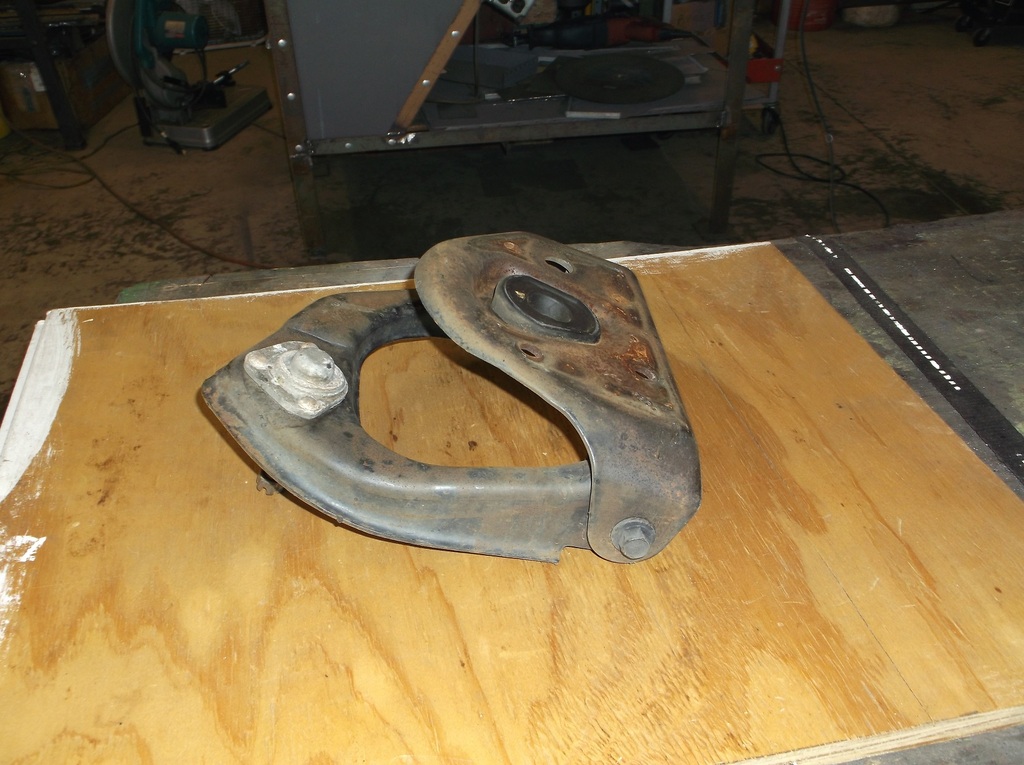
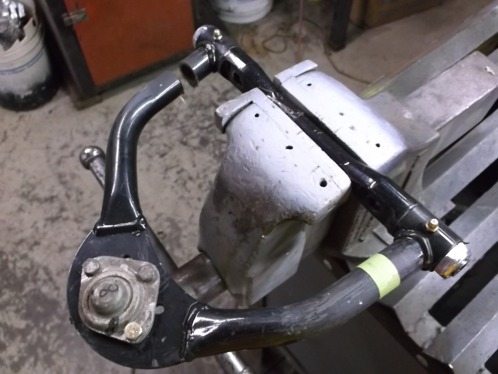
As I mentioned earlier, I have been picking up different parts for this build over the last couple years, thing that I think I can use and get at a good price. I picked up a set of Keyser tubular upper control arms off the Summit scratch and dent tables a while ago fpr $20 a piece. Like the oil pan and headers I am using these have nothing to do with a 4th gen or 3rd gen camaro. They are for metric body monte carlos street stock stock cars.
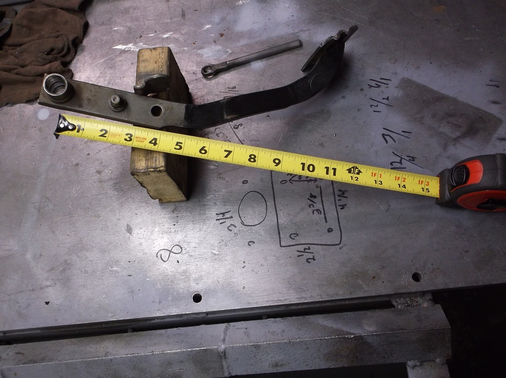
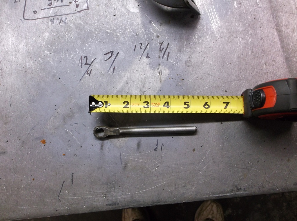
Here is a comparison.
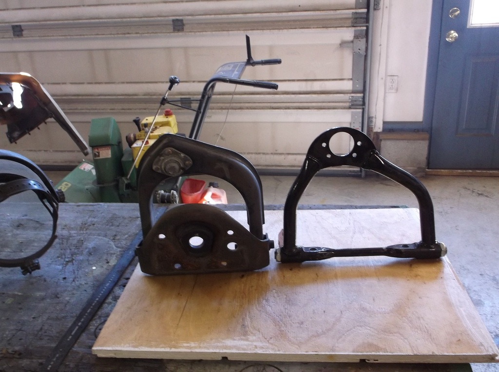
The monte carlo arm is 8 inches from center line of ball joint to center of pivot shaft. I was surprised to measure the 4th gen arm at 7 1/4 inches. I could cut and reweld the Keyser arms to match but I think I will leave as is for now. Biggest disadvantage of the longer arm is I lose a little camber gain in compression.
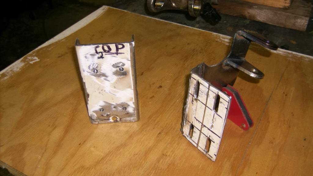
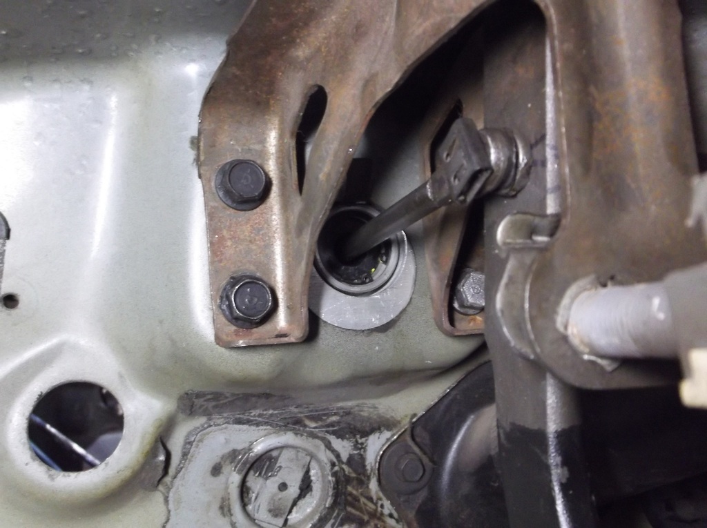
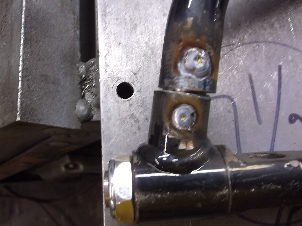
One thing I did have to modify was the ball joint mount. GM had used the same 4 bolt pattern, same diameter stud and same 10 degree taper for all rear wheel drive automotive applications from 1973 through the mid 90's impalas but the 4th gen has its own unique ball joints. 3 bolt mount, not 4 and the diameter of the stud is less than 1/2 inch at the largest point. The ball joint nut is only 10mm.
I had to take a rotary file bit and slot two of the holes inward about a 1/16 each side. I then drilled a new hole for the third bolt hole.
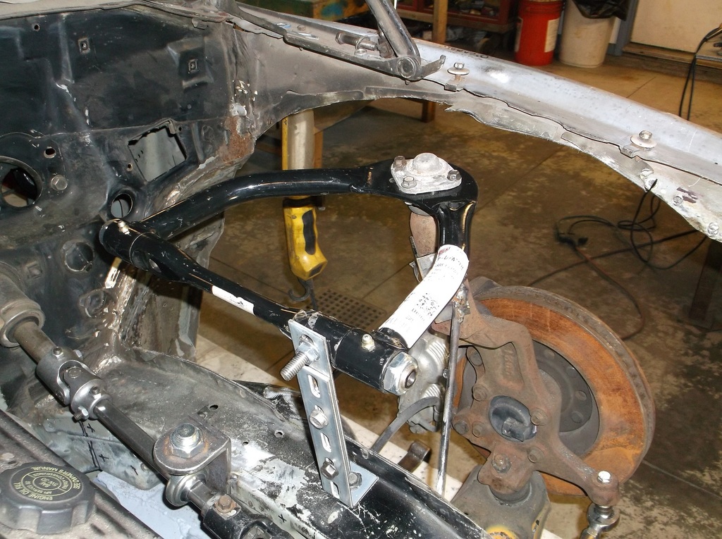
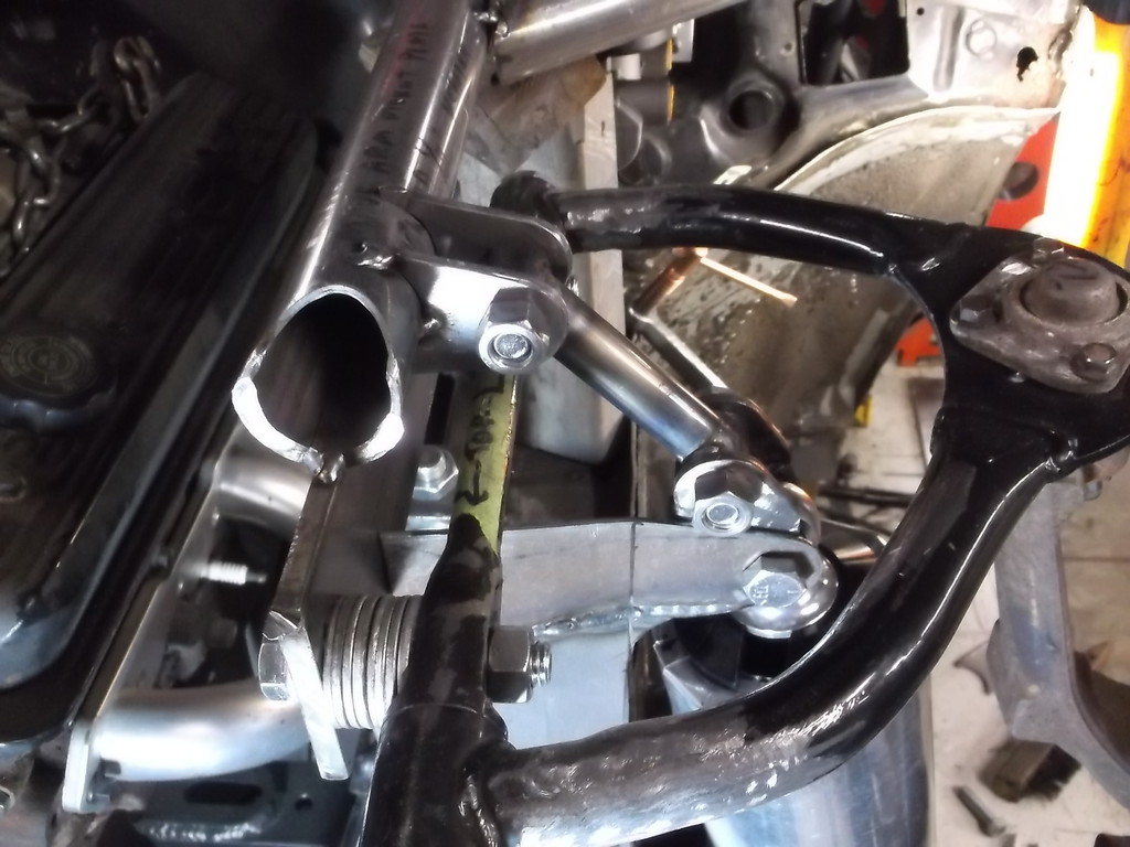
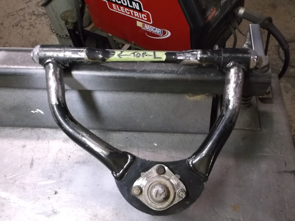
I mocked up the 4th gen a arm just to get a location.
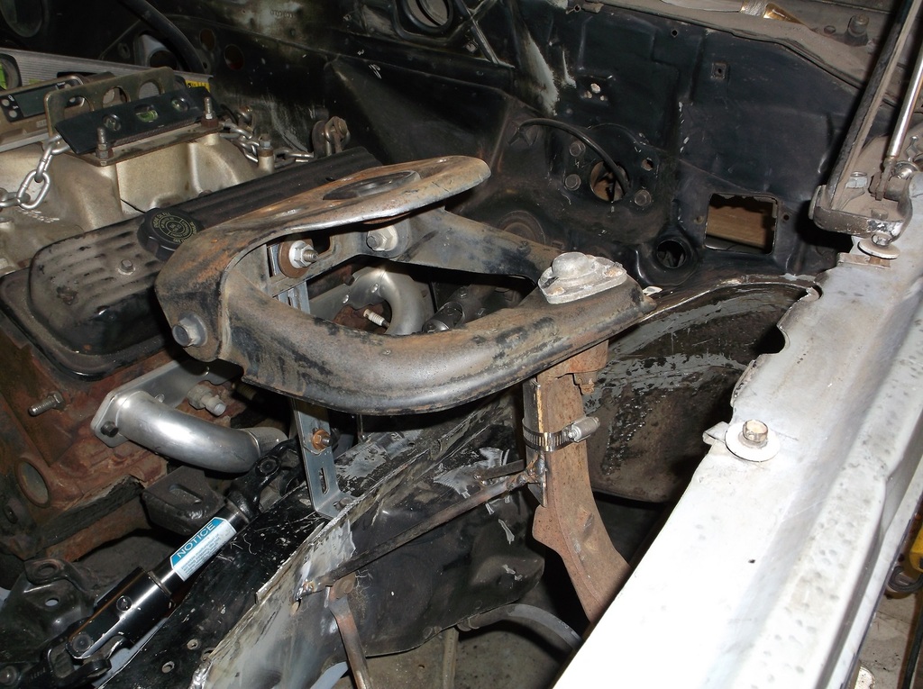
I think the tubular arm looks a lot better.
I thought I would be clever and mount the tubular arm with the offset to the rear but realized it would interfere with the upper shock mount. You can see from last pic to this one the offset. Note where the support is on the pivot shaft.


As I mentioned earlier, I have been picking up different parts for this build over the last couple years, thing that I think I can use and get at a good price. I picked up a set of Keyser tubular upper control arms off the Summit scratch and dent tables a while ago fpr $20 a piece. Like the oil pan and headers I am using these have nothing to do with a 4th gen or 3rd gen camaro. They are for metric body monte carlos street stock stock cars.
Here is a comparison.

The monte carlo arm is 8 inches from center line of ball joint to center of pivot shaft. I was surprised to measure the 4th gen arm at 7 1/4 inches. I could cut and reweld the Keyser arms to match but I think I will leave as is for now. Biggest disadvantage of the longer arm is I lose a little camber gain in compression.
One thing I did have to modify was the ball joint mount. GM had used the same 4 bolt pattern, same diameter stud and same 10 degree taper for all rear wheel drive automotive applications from 1973 through the mid 90's impalas but the 4th gen has its own unique ball joints. 3 bolt mount, not 4 and the diameter of the stud is less than 1/2 inch at the largest point. The ball joint nut is only 10mm.
I had to take a rotary file bit and slot two of the holes inward about a 1/16 each side. I then drilled a new hole for the third bolt hole.

I mocked up the 4th gen a arm just to get a location.


I think the tubular arm looks a lot better.

I thought I would be clever and mount the tubular arm with the offset to the rear but realized it would interfere with the upper shock mount. You can see from last pic to this one the offset. Note where the support is on the pivot shaft.

Thread Starter
Senior Member
Joined: Aug 2007
Posts: 682
Likes: 45
Re: Home brew road racer
I was all set to get some premade upper control arm brackets, laser cut an predrilled. I have seen them in catalogs many times. Too bad there is none for the monte carlo arms. They have about a 6 3/4 spread between the two mounting bolt and all the premade stuff I could find was a 6" spread. Oh well out comes the cutoff wheel and drill press and a piece of 5/16 steel plate.
I graphed out the control arm angles to give me a 2 or 3 inch roll center height. The lower the pivot shaft is in relation to the ball joint the higher the roll center. Dropping the shaft just 3/4" lower gets me to the 2 inch roll height and another 3/4 gets me to the 3". After spending what seemed like hours getting things lined up and deciding how to hang the mount and how everything has to tie together, shock mount, lateral bracing etc. I came up with this.
The top of the tube is level with the OE upper frame rail so there should be no clearance issue. Also the front of the bar will start to angle down to the main frame rail just forward of the a arm shaft.
The scribed line on the firewall is the top of the knee bar behind the dash. The tubing will will run thru the firewall and cowel and weld to the knee bar.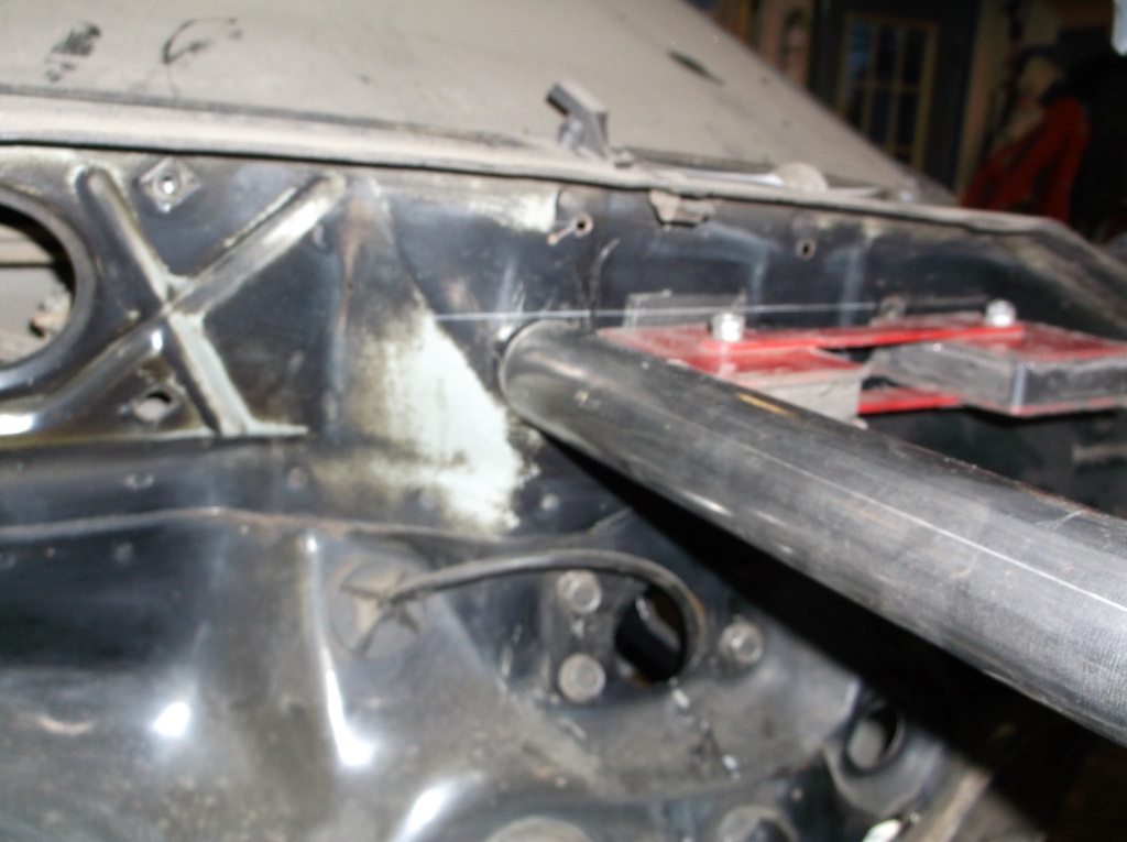
I will reinforce the corner of the firewall with 1/8" plate and add a diagonal brace like this.
In this pic you can see the top of the shock. It is about 6" from the top tube. It will have a angled mount coming off the main lower frame rail and I will add a removable Brace between the top of the shock mount and the upper tube rail. There will also be a Lateral brace running between the right and left top rail similar to a STB on a gen 3.
Heck this thing is starting to look like a race car.
I graphed out the control arm angles to give me a 2 or 3 inch roll center height. The lower the pivot shaft is in relation to the ball joint the higher the roll center. Dropping the shaft just 3/4" lower gets me to the 2 inch roll height and another 3/4 gets me to the 3". After spending what seemed like hours getting things lined up and deciding how to hang the mount and how everything has to tie together, shock mount, lateral bracing etc. I came up with this.

The top of the tube is level with the OE upper frame rail so there should be no clearance issue. Also the front of the bar will start to angle down to the main frame rail just forward of the a arm shaft.

The scribed line on the firewall is the top of the knee bar behind the dash. The tubing will will run thru the firewall and cowel and weld to the knee bar.

I will reinforce the corner of the firewall with 1/8" plate and add a diagonal brace like this.


In this pic you can see the top of the shock. It is about 6" from the top tube. It will have a angled mount coming off the main lower frame rail and I will add a removable Brace between the top of the shock mount and the upper tube rail. There will also be a Lateral brace running between the right and left top rail similar to a STB on a gen 3.

Heck this thing is starting to look like a race car.

Thread Starter
Senior Member
Joined: Aug 2007
Posts: 682
Likes: 45
Re: Home brew road racer
1o80b, thanks for following along. I hope I am keeping everyone amused with my insanity.
Not sure what you mean buy cleaning the welds. If you mean grinding them smooth, then no I am not. Grinding down a weld can severely weaken the weld joint, especially if the weld is to the top surface of a flat plate. I have tried to avoid making many unsightly bubblegum welds and will only grind down a weld to remove any sharp edges or points that i might get cut or snagged on.
A good weld is usually an attractive feature in an industrial sort of way. Granted I am not running a stack of dimes tig weld but I feel most of my beads don't look too bad.
Thread Starter
Senior Member
Joined: Aug 2007
Posts: 682
Likes: 45
Re: Home brew road racer
I am getting things ready to mount the new upper tube rail. I ordered some pre bent ones from Competition Engineeeing CEE-3186 from Summit Racing. Hopefully they will be in by the end of the week.
Tricky part is to cut a 1 5/8 hole through the firewall and 3 other layers of steel and keep it all in line so the the tube will be straight and level. I measured the height of the top of the knee bar and transferred that to a line on the fire wall and onto the welded plate that mounts the steering column inside. From mocking up the upper control arm I knew the location of where the tube had to pass though the firewall. To transfer that location to the inside of the car I positioned my 48" level vertically outside of the car at the outer edge of my ramp and took a measurement to the center of the hole that the tube would pass through. I repositioned the level just past the bottom of the A pillar and marked the center line for the hole inside.
Here is how it turned out.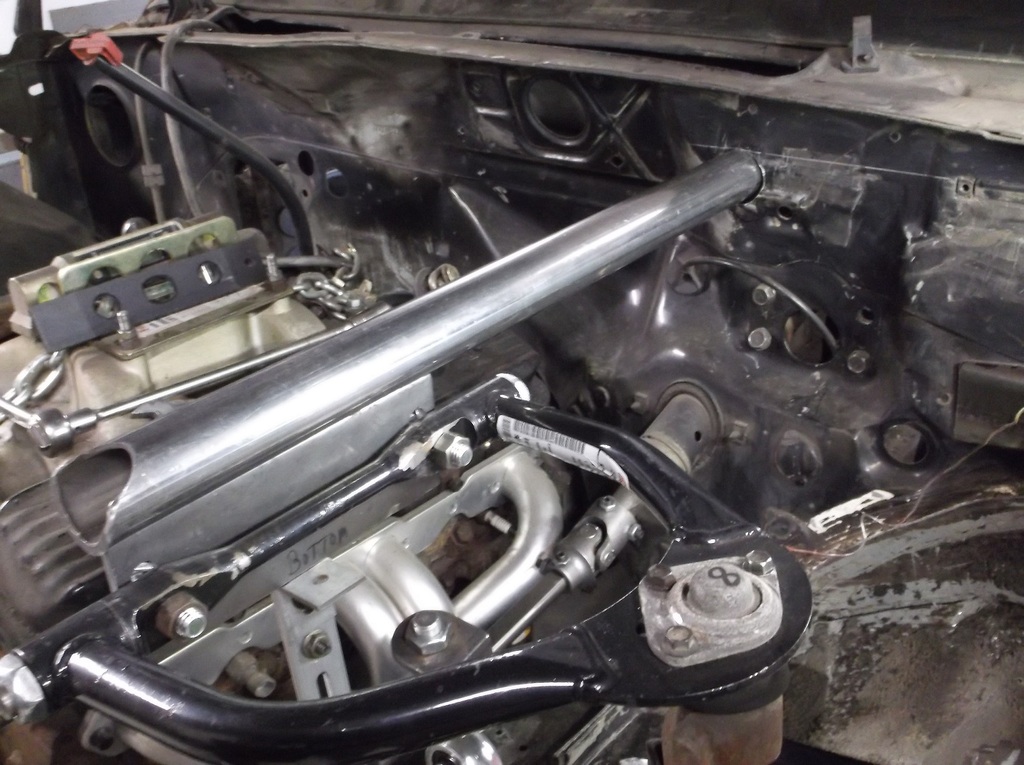
As you can see in the one pic I was a little off side to side on the inside location but dead on for the height. A simple notch on the end of the tube and it will be easy to weld in. I will probably cut some 1/8" cover plates to fit closer around the tubing and weld them in to seal everything up. There is also a hole in the back of the cowel where the wiper linkage runs. It has about an 1/8" gap around most of it. I can't get in there to weld it shut so seam sealer or silicone will have to do. I am hoping to still have functional wipers after all this. I am looking at modifying the linkage to loop over the bar and keep everything lined up.
Tricky part is to cut a 1 5/8 hole through the firewall and 3 other layers of steel and keep it all in line so the the tube will be straight and level. I measured the height of the top of the knee bar and transferred that to a line on the fire wall and onto the welded plate that mounts the steering column inside. From mocking up the upper control arm I knew the location of where the tube had to pass though the firewall. To transfer that location to the inside of the car I positioned my 48" level vertically outside of the car at the outer edge of my ramp and took a measurement to the center of the hole that the tube would pass through. I repositioned the level just past the bottom of the A pillar and marked the center line for the hole inside.
Here is how it turned out.


As you can see in the one pic I was a little off side to side on the inside location but dead on for the height. A simple notch on the end of the tube and it will be easy to weld in. I will probably cut some 1/8" cover plates to fit closer around the tubing and weld them in to seal everything up. There is also a hole in the back of the cowel where the wiper linkage runs. It has about an 1/8" gap around most of it. I can't get in there to weld it shut so seam sealer or silicone will have to do. I am hoping to still have functional wipers after all this. I am looking at modifying the linkage to loop over the bar and keep everything lined up.
Thread Starter
Senior Member
Joined: Aug 2007
Posts: 682
Likes: 45
Re: Home brew road racer
Just a 1 5/8 hole saw. Cutting the firewall was no problem. The inner cowel panel took a lot more effort. To get the location I slid my length of tubing through the outer hole and lined it up on the upper control arm bracket to make sure it was level and square. I pushed it to the back of the cowel and and traced around the tube with a sharpie. This is about 8 inches behind the firewall and the rear wall has a gradual curve at the bottom that the hole had to be drilled through.
Because the location is so far back and only access is through the top of the cowel I had to put a 1/4" awl in a 12" drill bit extender and used that to center punch the location to drill the 2nd hole. I could only eyeball the center but hit it pretty close. To cut out the 2nd hole I mounted the hole saw in the extender and cut it out at an downward angle. This caused the hole to be a bit oblong due to the curved surface and also the opening was not tall enough to let the tubing pass through. The hole was also a little too far to the right.
To correct all this I mounted a 3/8 rotary file bit in the extension and after outlining the location with a sharpie again, opened it up just enough to let me tap the tubing through the whole.
For the hole above the steering column i used the hole saw attached directly
to the drill but again had to drill at an angle over the top of the knee bar. with all 3 holes cut out i could see that the interior whole was 3/8 to a 1/2 too far to the left. The amount of metal needed to be removed was too thick and too wide to use the rotary file so I fired up the torch and cut out just enough to get the tubing through and still line up with the upper control arm bracket.
This may sound like a lot but really wasn't too bad. The whole job probably took an hour and a half. Having to use the drill extension caused the hole saw to chatter a lot and the saw kept vibrating loose, I ended up tack welding the arbor for the saw to the drill extension to make it work.
Hopefully the right side will turn out as well. With a little luck I could have this suspension swap done in the next couple weeks and set the car down on its wheels for the first time in 4 years.
Thread Starter
Senior Member
Joined: Aug 2007
Posts: 682
Likes: 45
Re: Home brew road racer
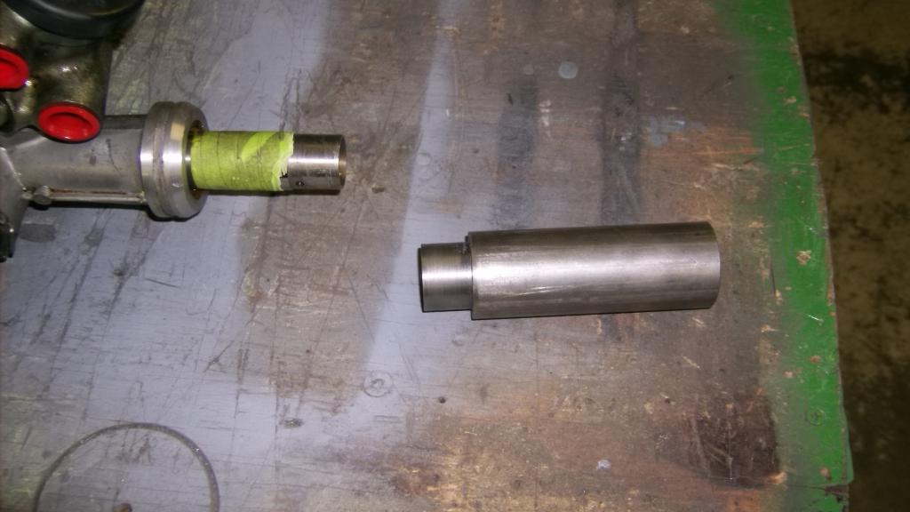
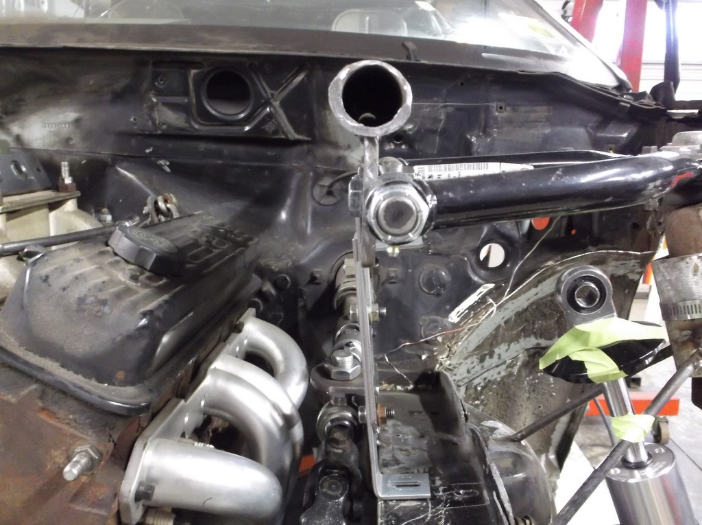
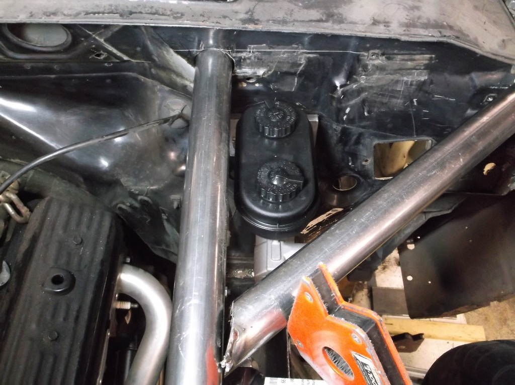
Still waiting for the front tubes to come in so I decided to mount the master cylinder. I am going with manual brakes and using the mopar style master cylinder. This is similar to the BMR MBK001 kit that Summit sells for $179.00.
http://static.summitracing.com/globa...bk001_w_ml.jpg
I accomplished the same thing for about $35.00 using a Dorman master cylinder Summit part number DHB-M99294 and a piece of 1/2" thick aluminum.
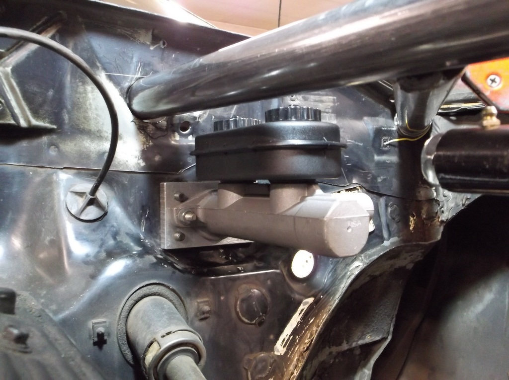
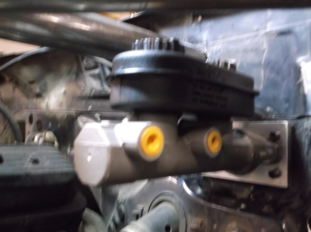
To do this swap correctly the pin on the master cylinder needs to be moved up about 1 3/4 inches. This accomplishes two things; 1. it aligns the push rod with the back of the master cylinder so that it pushes straight into the piston, and 2. it increases the pedal ratio. The length of the pedal is about 12" from center of top pivot pin to bottom of pedal pad. The stock push rod pin location is almost 4" from the top pivot pin giving a pedal ratio of just over 3:1. This works for the power brakes but would require some serious leg muscles to stop with manual brakes. Moving the pin up put the push rod pin at 2 1/8" from the top pivot giving me a 6:1 ratio. much more effective and user friendly.
i ground the mushroom head of the back of the pin and drove the pin out with a punch and hammer. A 7/16 drill bit makes a hole that has a bit of a press fit. For extra insurance I welded the back side of the pin the the pedal arm.
The last part of the modification is to make a push rod. I disassembled the booster assembly and removed the pushrod. holding the brake pedal in the fully released position against the brake light switch I took my measurement. I cut the rod a tad long and ground the cut end to a ball shape and sanded it nice and smooth with some emery cloth. It took a couple tries to sneak up on the exact length to get the master cylinder to come back to full release. You have a little wiggle room if your too short as you can turn in the brake light switch.
http://static.summitracing.com/globa...bk001_w_ml.jpg
I accomplished the same thing for about $35.00 using a Dorman master cylinder Summit part number DHB-M99294 and a piece of 1/2" thick aluminum.


To do this swap correctly the pin on the master cylinder needs to be moved up about 1 3/4 inches. This accomplishes two things; 1. it aligns the push rod with the back of the master cylinder so that it pushes straight into the piston, and 2. it increases the pedal ratio. The length of the pedal is about 12" from center of top pivot pin to bottom of pedal pad. The stock push rod pin location is almost 4" from the top pivot pin giving a pedal ratio of just over 3:1. This works for the power brakes but would require some serious leg muscles to stop with manual brakes. Moving the pin up put the push rod pin at 2 1/8" from the top pivot giving me a 6:1 ratio. much more effective and user friendly.

i ground the mushroom head of the back of the pin and drove the pin out with a punch and hammer. A 7/16 drill bit makes a hole that has a bit of a press fit. For extra insurance I welded the back side of the pin the the pedal arm.

The last part of the modification is to make a push rod. I disassembled the booster assembly and removed the pushrod. holding the brake pedal in the fully released position against the brake light switch I took my measurement. I cut the rod a tad long and ground the cut end to a ball shape and sanded it nice and smooth with some emery cloth. It took a couple tries to sneak up on the exact length to get the master cylinder to come back to full release. You have a little wiggle room if your too short as you can turn in the brake light switch.


Thread Starter
Senior Member
Joined: Aug 2007
Posts: 682
Likes: 45
Re: Home brew road racer
Still no front tubes. i got a post card saying maybe the 24th. I'm bummed. Anyway I picked up some mounting brackets and tabs at Summit from Allstar. I'll try and pre fit the coilovers to the short tube that I have mocked up. A few screens back I show the front shock positioned close to the lower ball joint, about 2 inches farther out than stock. I had thought that this would give the best control over the wheel and it would be if the shock could stand nearly upright. As it is though to mount the shock that far out it would have to lay back about 25 degrees to clear the spindle and upper control arm. At that angle I lose about 20% of my spring rate so 400lb/in spring become 320's. Also at that angle the shaft of the shock travels very little in relation to wheel travel so you lose a lot of the dampening effect. I moved the lower mount back to the OE location and my shock now angles back about 13 degrees. According to the QA1 chart in their catalog I should only lose about 7% of the spring rate.
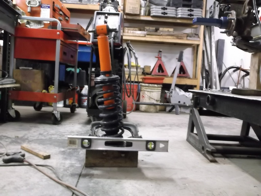
Because I am making these mounts from scratch I had to come up with a way to hold the shock at its ride height length of 14 inches and also simulate the 3 1/2 OD of the coil spring. After looking around the garage I found a length of 4" drier vent tubing. I am sure this is how all of the big name car fabricators do it!!!!!!!!!!
 .
.
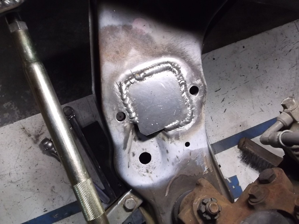
To mount the shock I had to plate over the recess in the factory control arm. A 2.5 x 2.5 piece of 3/16 plate did the job.
With the bottom mount tacked in place I set out to locate the top of the shock. No matter what I did I could not get the top of the shock to clear the upper A-arm when I let the suspension drop. I was stumped. My coil over setup is half the length of the 4th gen and an 1 1/2 smaller in OD than the stock setup so why the interference??? I finally pulled out one of the 4th gen shock assemblies to see why the the stock monstrosity worked and my half size race part wouldn't. And here is what I discovered...
The 4th gen shock angles back more than 12 degrees from bottom to top. I was trying to mount my coilover as near vertical as I could but couldn't get out of the way of the arc of the control arm. So with this new bit of knowledge we moved the top of the shock back until we had sufficient clearance all around and settled on about 10 degrees lay back. I will probably weld the upper and lower mounting tabs in at the 10 degrees so that the the pivoting shock bushings are centered at ride height and will have full articulation through the shock travel.
To mount the top of the shock I want to tie it into both the lower OE frame rail and the new upper tube rail as well as a lateral brace similar to an STB on a 3rd gen. Should look something like this.
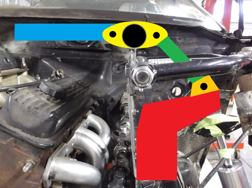
The large red mount will extend from the bottom frame rail to top tube, The green rod will have to be removable to get the a-arm in and out. The blue bar will be made from 1 1/4x.120 tubing and attach with 5/8 heims, same as the tie rod ends.
Because I am making these mounts from scratch I had to come up with a way to hold the shock at its ride height length of 14 inches and also simulate the 3 1/2 OD of the coil spring. After looking around the garage I found a length of 4" drier vent tubing. I am sure this is how all of the big name car fabricators do it!!!!!!!!!!

 .
.To mount the shock I had to plate over the recess in the factory control arm. A 2.5 x 2.5 piece of 3/16 plate did the job.


With the bottom mount tacked in place I set out to locate the top of the shock. No matter what I did I could not get the top of the shock to clear the upper A-arm when I let the suspension drop. I was stumped. My coil over setup is half the length of the 4th gen and an 1 1/2 smaller in OD than the stock setup so why the interference??? I finally pulled out one of the 4th gen shock assemblies to see why the the stock monstrosity worked and my half size race part wouldn't. And here is what I discovered...

The 4th gen shock angles back more than 12 degrees from bottom to top. I was trying to mount my coilover as near vertical as I could but couldn't get out of the way of the arc of the control arm. So with this new bit of knowledge we moved the top of the shock back until we had sufficient clearance all around and settled on about 10 degrees lay back. I will probably weld the upper and lower mounting tabs in at the 10 degrees so that the the pivoting shock bushings are centered at ride height and will have full articulation through the shock travel.


To mount the top of the shock I want to tie it into both the lower OE frame rail and the new upper tube rail as well as a lateral brace similar to an STB on a 3rd gen. Should look something like this.

The large red mount will extend from the bottom frame rail to top tube, The green rod will have to be removable to get the a-arm in and out. The blue bar will be made from 1 1/4x.120 tubing and attach with 5/8 heims, same as the tie rod ends.
Thread Starter
Senior Member
Joined: Aug 2007
Posts: 682
Likes: 45
Re: Home brew road racer
Where does the left side of the blue bar mount to?
The left (driver side) will attach to tabs welded to the upper tube. The right side will mount the same tieing both sides together like a strut tower brace does.
Also, Why does it look like you bolted a solid bar from the A arm to the frame?
The left (driver side) will attach to tabs welded to the upper tube. The right side will mount the same tieing both sides together like a strut tower brace does.
Also, Why does it look like you bolted a solid bar from the A arm to the frame?
Thread Starter
Senior Member
Joined: Aug 2007
Posts: 682
Likes: 45
Re: Home brew road racer
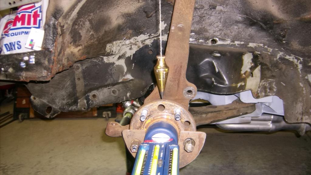
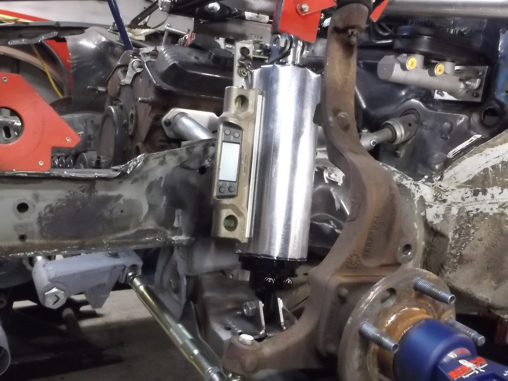
I am a firm believer in divine intervention (I am too stupid to have gotten this far in life on my own) and that all things happen for a reason. With the delay in getting the top rails I used the time to double check my measurements and recheck the alignment. I use a bubble gauge from Rebco. Camber is a direct read out, just pop it on the hub and take the reading from the center of the bubble. Caster is a bit more complex requiring you to turn the wheel outward 20*, center the bubble in the caster vial and then turn the wheel in 20* to get the caster measurement.
I couldn't do this until I had a secure mount for the upper A-arm. When I initially set the location for the spindle I ASSUMED that when the upper horizontal edge of the front bearing assembly was level the spindle would be at 0* caster. I wanted to build in about 5* positive caster in my mount location so adjusting to 6 or 7 degrees would not take so many shims. Here is a pic of the initial mounting position. The red arrow shows the horizontal edge of the hub assembly. I set up a digital level on that edge and leaned the top of the spindle back about 6 *

So now that the upper arm is mounted I thought it wise to check it with the gauge. NEVER, EVER ASSUME. The alignment gauge showed almost 12* positive caster. I checked and double checked both the gauge reading and the reading from my digital level. They should be about the same IF my Assumption was correct. I had to cut the upper a-arm mount off of the top tube and move it forward almost 2" to get the upper edge of the hub assembly horizontal. With my level showing zero degrees I checked caster with the Rebco gauge and it read a little over 5* positive caster. The GM engineers had designed in positive caster to the spindle just like what I had wanted to do.
I had to completely redo the upper mount location and realign the coilover mounts. The good news everything fell into place and the goofy angle of the coilover posted in the last installment is gone and the shock now mounts vertiacal, front to rear, with about a 12* layback towards the frame rail.
This pic shows how far forward I had to move the a-arm mount. Originally it was just back from the end of the tube.
With that mistake corrected I wanted to see what kind of adjustment I could get as far as static caster and camber. I wanted to be able to dial in as much as 3* negative camber and 7 to 8 degrees of caster. Another disappointment when all I could get was about 1.5 degrees negative camber. To get more I would have to relocate the upper a-arm mount farther inboard closer to the engine. This was not something I wanted to do. The other option was to shorten the a-arm. These arms were 8" from center of shaft to center of the ball joint. The 4th gen arm were 7 1/4". I opted to shorten the arms.
I marked the cut with 3/4 masking tape
3/4 x .065 wall tube for plug weld.
After the plug weld I used the cutoff wheel and cut a gap between the a-arm tubing. This allowed the weld to penetrate down to the 3/4 tubing inside. this gave me a nice deep weld. i know I just gave a sermon on the evils of grinding welds but because I was confident in the depth of penetration I went ahead and smoothed these out. I think also it will be easier to detect any cracking on the smoother surface.
I couldn't do this until I had a secure mount for the upper A-arm. When I initially set the location for the spindle I ASSUMED that when the upper horizontal edge of the front bearing assembly was level the spindle would be at 0* caster. I wanted to build in about 5* positive caster in my mount location so adjusting to 6 or 7 degrees would not take so many shims. Here is a pic of the initial mounting position. The red arrow shows the horizontal edge of the hub assembly. I set up a digital level on that edge and leaned the top of the spindle back about 6 *

So now that the upper arm is mounted I thought it wise to check it with the gauge. NEVER, EVER ASSUME. The alignment gauge showed almost 12* positive caster. I checked and double checked both the gauge reading and the reading from my digital level. They should be about the same IF my Assumption was correct. I had to cut the upper a-arm mount off of the top tube and move it forward almost 2" to get the upper edge of the hub assembly horizontal. With my level showing zero degrees I checked caster with the Rebco gauge and it read a little over 5* positive caster. The GM engineers had designed in positive caster to the spindle just like what I had wanted to do.
I had to completely redo the upper mount location and realign the coilover mounts. The good news everything fell into place and the goofy angle of the coilover posted in the last installment is gone and the shock now mounts vertiacal, front to rear, with about a 12* layback towards the frame rail.
This pic shows how far forward I had to move the a-arm mount. Originally it was just back from the end of the tube.

With that mistake corrected I wanted to see what kind of adjustment I could get as far as static caster and camber. I wanted to be able to dial in as much as 3* negative camber and 7 to 8 degrees of caster. Another disappointment when all I could get was about 1.5 degrees negative camber. To get more I would have to relocate the upper a-arm mount farther inboard closer to the engine. This was not something I wanted to do. The other option was to shorten the a-arm. These arms were 8" from center of shaft to center of the ball joint. The 4th gen arm were 7 1/4". I opted to shorten the arms.
I marked the cut with 3/4 masking tape


3/4 x .065 wall tube for plug weld.


After the plug weld I used the cutoff wheel and cut a gap between the a-arm tubing. This allowed the weld to penetrate down to the 3/4 tubing inside. this gave me a nice deep weld. i know I just gave a sermon on the evils of grinding welds but because I was confident in the depth of penetration I went ahead and smoothed these out. I think also it will be easier to detect any cracking on the smoother surface.

Thread Starter
Senior Member
Joined: Aug 2007
Posts: 682
Likes: 45
Re: Home brew road racer
With the a-arm and shock finally in the right location I went to work on making the short upper brace that would link the top of the shock to the top rail. I used the same 3/4 tubing here as in the a-arm mod. This had to be removable so the a-arm could be removed if needed.
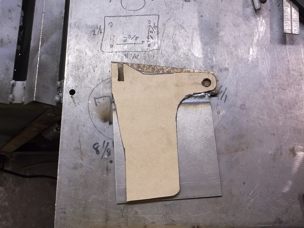
Now I needed to tie the upper and lower rails together and also tie in to the upper shock mount. after a few sketches I came up with this template.
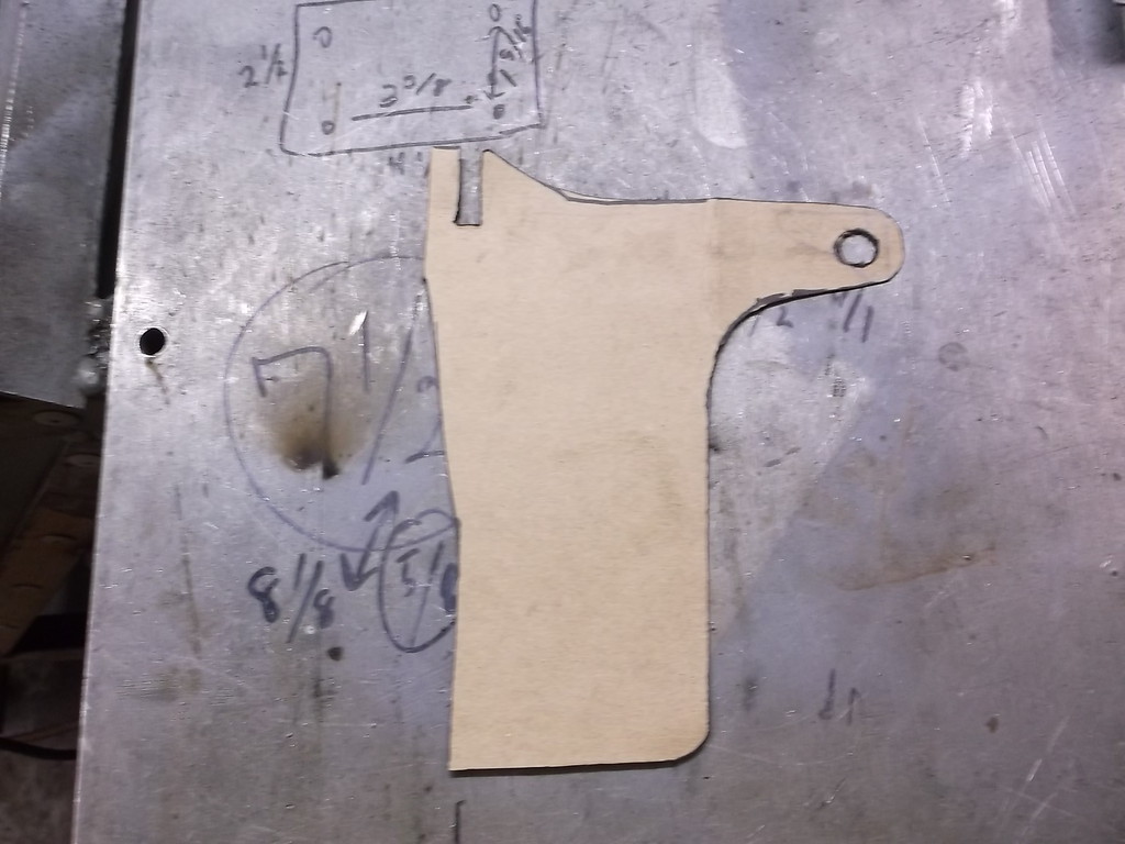
Which transfered onto steel. Each plate required an 8"x7" piece of 1/8 steel. I have an abundance of 6x6 pieces and some longer, narrower pieces. So in keeping with the low buck theme I welded the plates together to get what I needed. I first tack welded the plates at both ends and the center. Then took my cut off wheel and cut down the parting line till I was nearly through the other side. I welded the seam on the one side, flipped it over and did the same to the back side. I don't think I will have a strength issue with these.
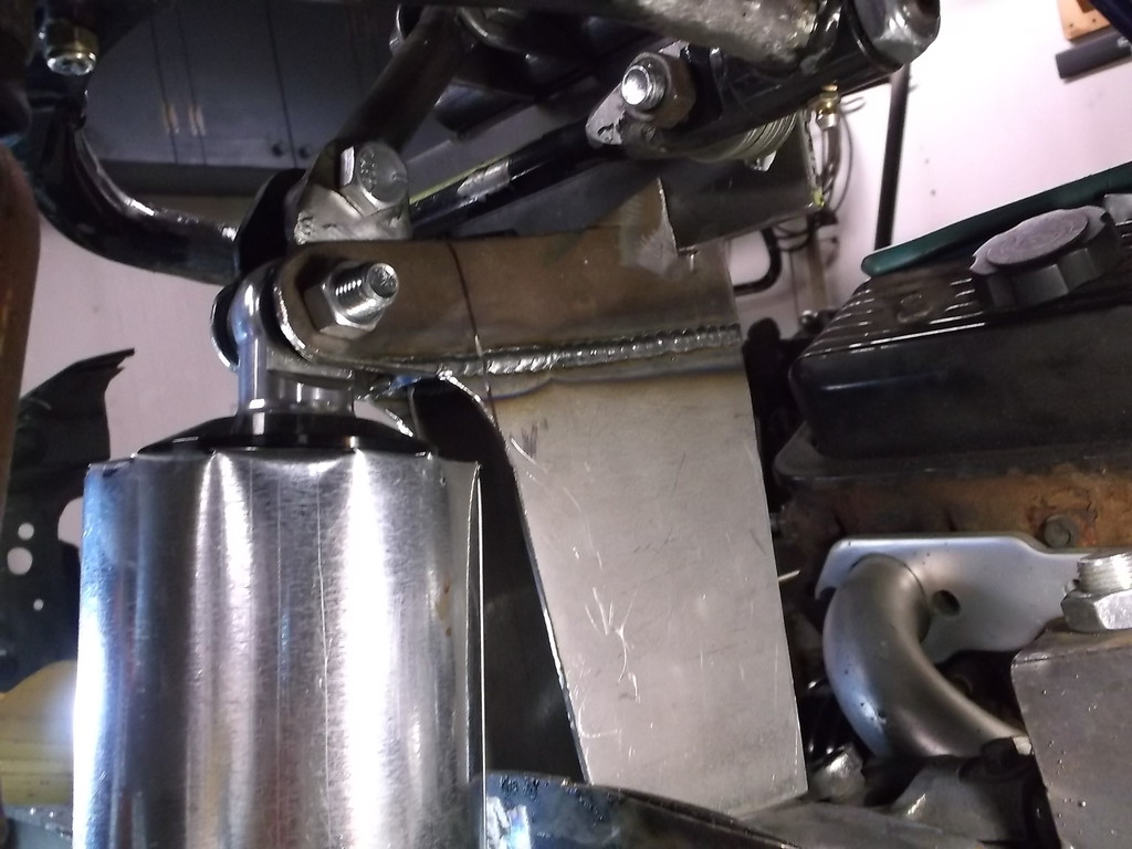
I reinforced the OE frame with 1/8 plate as well. The two plates flare out from 1 1/2 wide at the shock mount to 3 1/2 at the end of the frame. This will get boxed in front, back and top. Not sure if I should add any internal bracing before I close it up. Norm or anyone have an opinion on this?
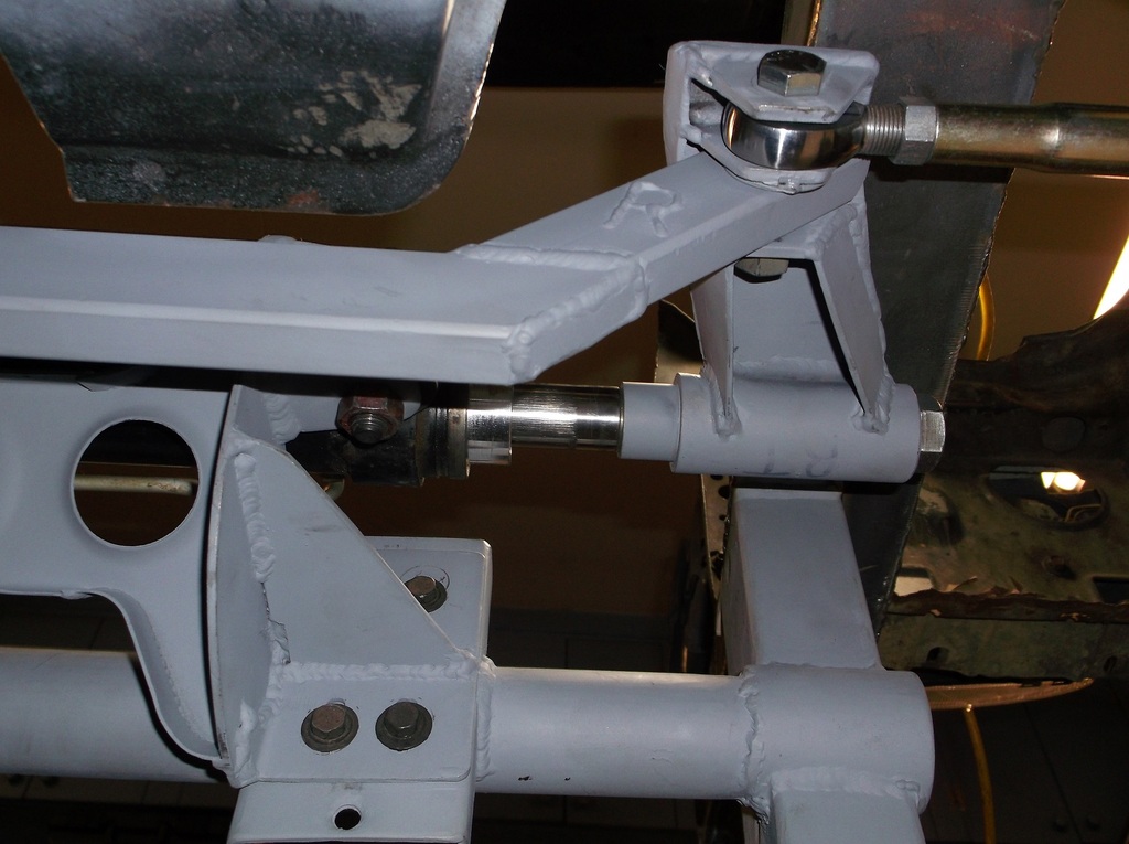
Here is a good pic of how things line up now that the spindle is in the correct location.

Now I needed to tie the upper and lower rails together and also tie in to the upper shock mount. after a few sketches I came up with this template.

Which transfered onto steel. Each plate required an 8"x7" piece of 1/8 steel. I have an abundance of 6x6 pieces and some longer, narrower pieces. So in keeping with the low buck theme I welded the plates together to get what I needed. I first tack welded the plates at both ends and the center. Then took my cut off wheel and cut down the parting line till I was nearly through the other side. I welded the seam on the one side, flipped it over and did the same to the back side. I don't think I will have a strength issue with these.


I reinforced the OE frame with 1/8 plate as well. The two plates flare out from 1 1/2 wide at the shock mount to 3 1/2 at the end of the frame. This will get boxed in front, back and top. Not sure if I should add any internal bracing before I close it up. Norm or anyone have an opinion on this?

Here is a good pic of how things line up now that the spindle is in the correct location.

Thread Starter
Senior Member
Joined: Aug 2007
Posts: 682
Likes: 45
Re: Home brew road racer
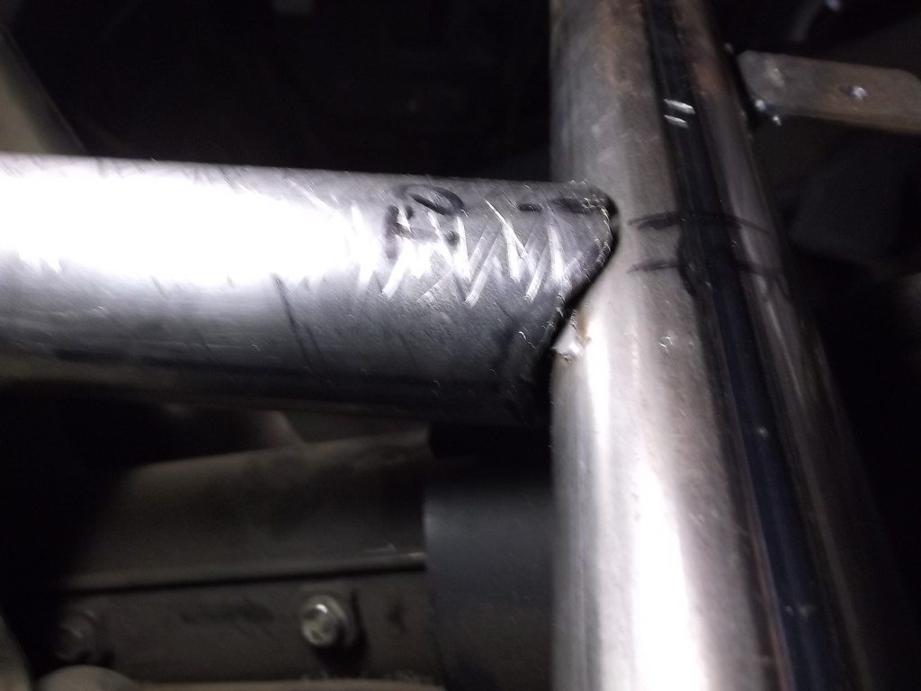
I had to cancel the order for the Comp Engineering rails and reorder from Allstar. They showed up late Tuesday. Having done so much preliminary work it did not take long to get the rail cut to size and installed.
The rail is 65" OAL, the leg is 14" from underside of rail and it is bent at a 25* angle.
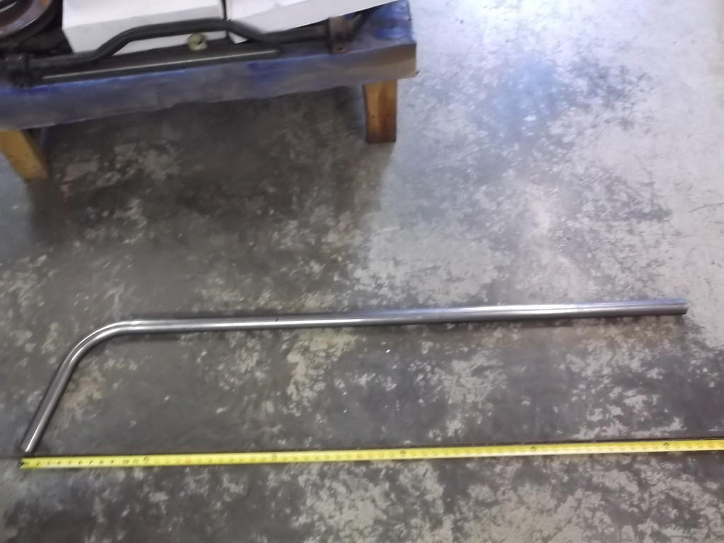
I decided on a length of 53" and it slipped right in place.
 .
.
I marked the end of the tube inside the car and notched it with my cut off wheel.
The front end of the tube is a little trickier as it has to conform to compound angles. I tried a couple time to mark and cut the tube but no luck. Besides the tube coming down at a 25* angle it is also rotated slightly to the outside as the tube runs parallel to but just inside the path of the factory frame rail. The OE rail at this point runs downhill from front to back and uphill from inside to out. I ended up cutting the bottom of the tube so ti sat about 1/4" above the OE rail and used a piece of cardboard tube from gift wrap paper to cut a pattern that would conform to all of the angles. When I had the shape right I transferred that to a piece of 1 3/4 od tubing and cut it with the cutoff wheel.
The 1 3/4 tubing id is too small to fit over the 1 5/8 tubing the top rail is made from so I split the tube and spread it to fit over the 1 5/8. So I ended up with this...
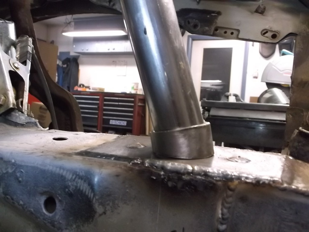
as you can see I also reinforced this area with 1/8 plate as well. My little collar does have about a 3/8 gap in the back but nothing a small piece of scrap and a little weld can't fix.
 .
.
The rail is 65" OAL, the leg is 14" from underside of rail and it is bent at a 25* angle.

I decided on a length of 53" and it slipped right in place.
 .
.I marked the end of the tube inside the car and notched it with my cut off wheel.

The front end of the tube is a little trickier as it has to conform to compound angles. I tried a couple time to mark and cut the tube but no luck. Besides the tube coming down at a 25* angle it is also rotated slightly to the outside as the tube runs parallel to but just inside the path of the factory frame rail. The OE rail at this point runs downhill from front to back and uphill from inside to out. I ended up cutting the bottom of the tube so ti sat about 1/4" above the OE rail and used a piece of cardboard tube from gift wrap paper to cut a pattern that would conform to all of the angles. When I had the shape right I transferred that to a piece of 1 3/4 od tubing and cut it with the cutoff wheel.

The 1 3/4 tubing id is too small to fit over the 1 5/8 tubing the top rail is made from so I split the tube and spread it to fit over the 1 5/8. So I ended up with this...

as you can see I also reinforced this area with 1/8 plate as well. My little collar does have about a 3/8 gap in the back but nothing a small piece of scrap and a little weld can't fix.
 .
. Thread Starter
Senior Member
Joined: Aug 2007
Posts: 682
Likes: 45
Re: Home brew road racer
With the rail tacked up in place it was time to verify all of the measurements and see if all of this work was worth the effort. I am using 1/2" flat washers for temporary alignment shims and even though the stack looks quite thick it is only 1 1/16 total. With that stack of shims I have a static camber of -5/8*. I was shooting for -1/2* so not too bad. For caster I removed 2 shims from the rear stack and that gave me +6* caster. I tried several different combos of front and rear shims and the adjustments are totally predictable and repeatable. Pulling out all but 3 of the washers in the front stack and all of the washers in the rear stack gives me my most aggressive "track day" setup of -2 3/4* camber and +6 1/2* caster. The plan is to make up some thick spacers 3/8" and 1/2", that can be pulled out together or separately that would let me adjust the camber without changing the caster setting.
I also checked for camber gain. That was one of the primary factors in wanting to convert to a double a-arm suspension in the first place. Regardless of the initial static camber setting i measured a consistent 1 1/2* gain in negative camber thru 3" of compression. The gain was very linear at about 1/2 degree per inch of travel. I also checked for camber loss when the suspension drops and was very surprised that there is none. My -5/8* camber was consistent through 2 1/2 inches of drop.
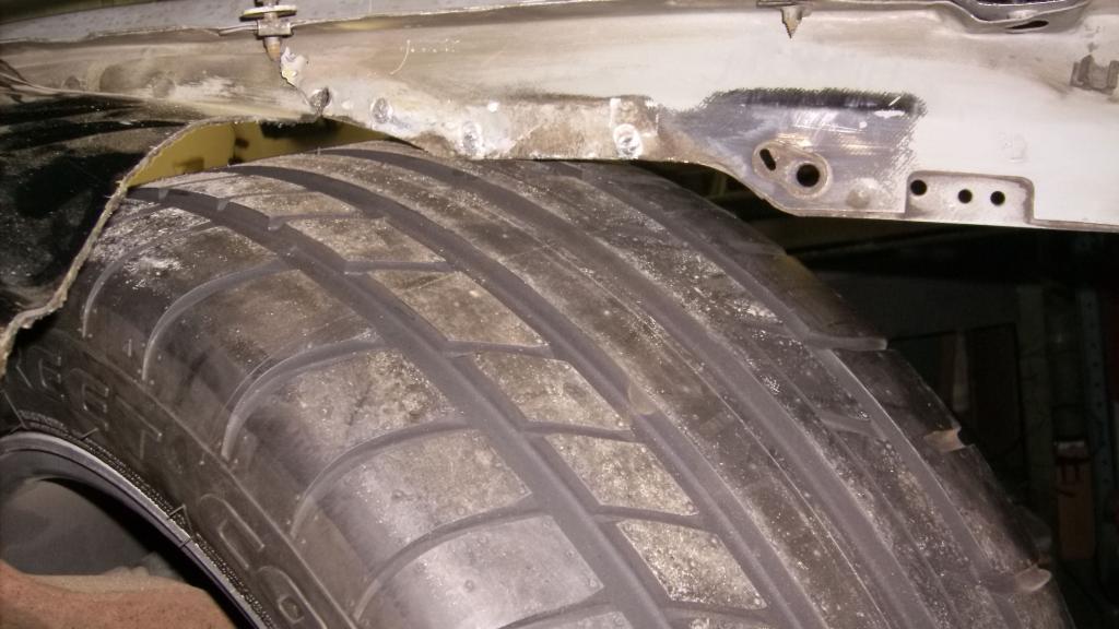
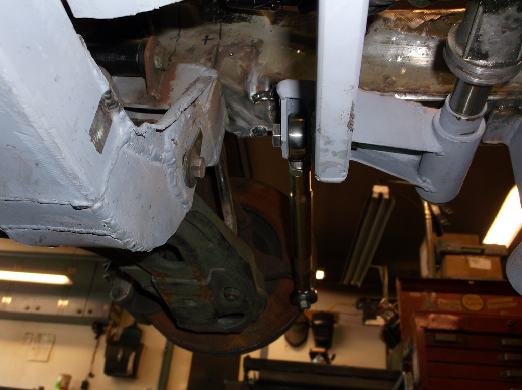
here is a pic of the upper ball joint at 3" compression (up travel). It clears the under side of the stick fiberglass hood by about 1/2".
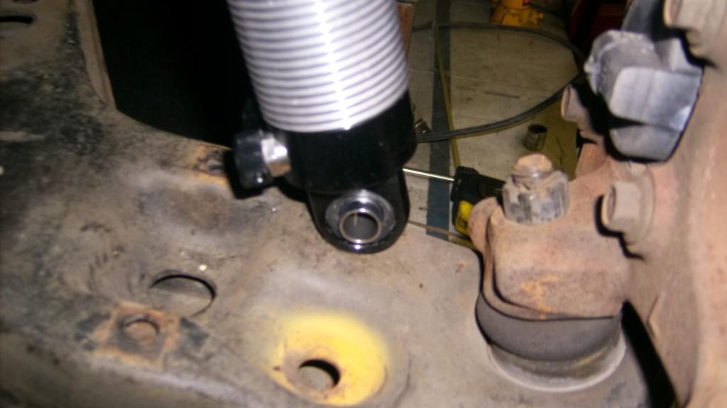
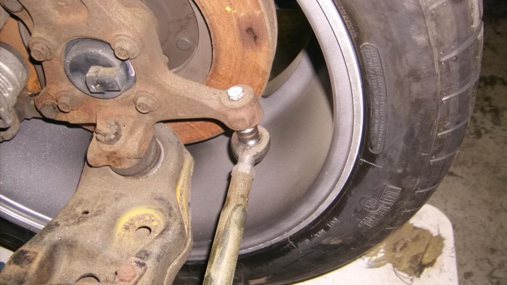
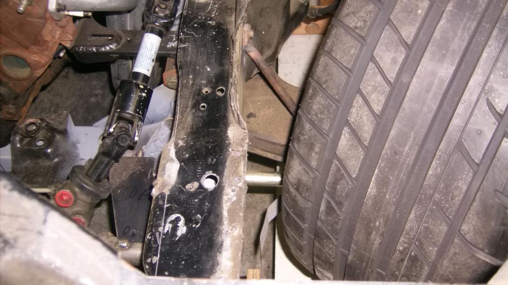
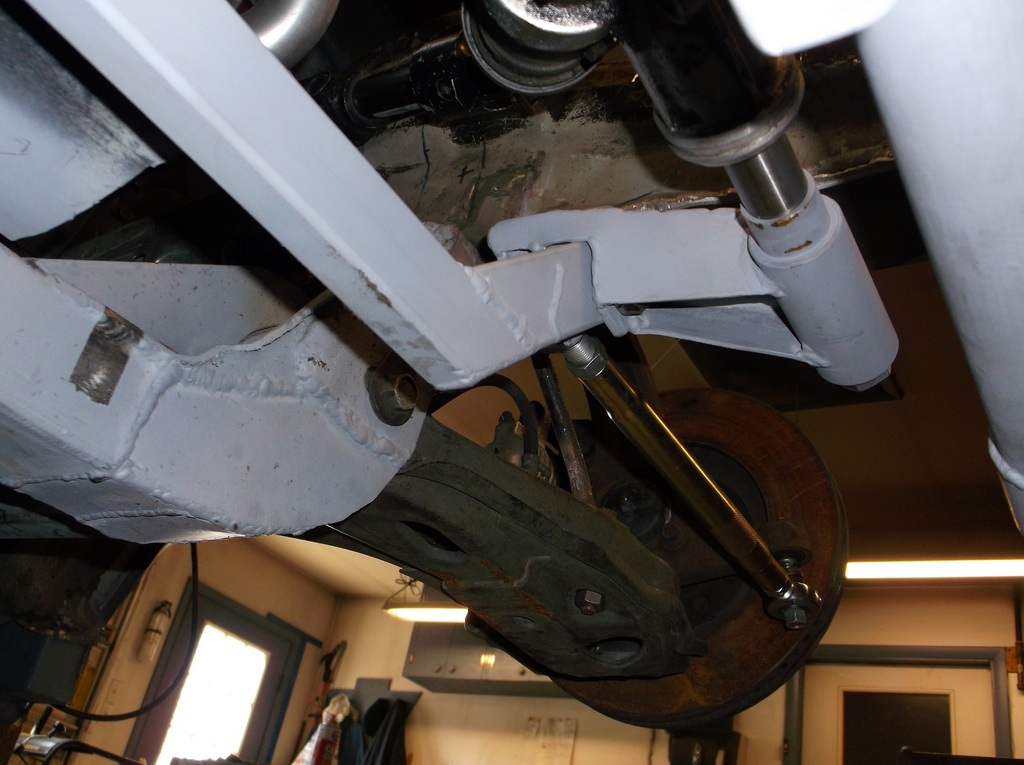
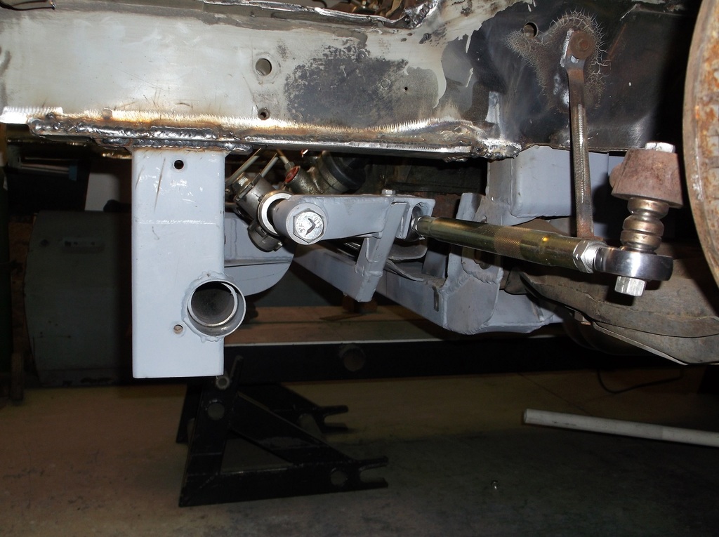
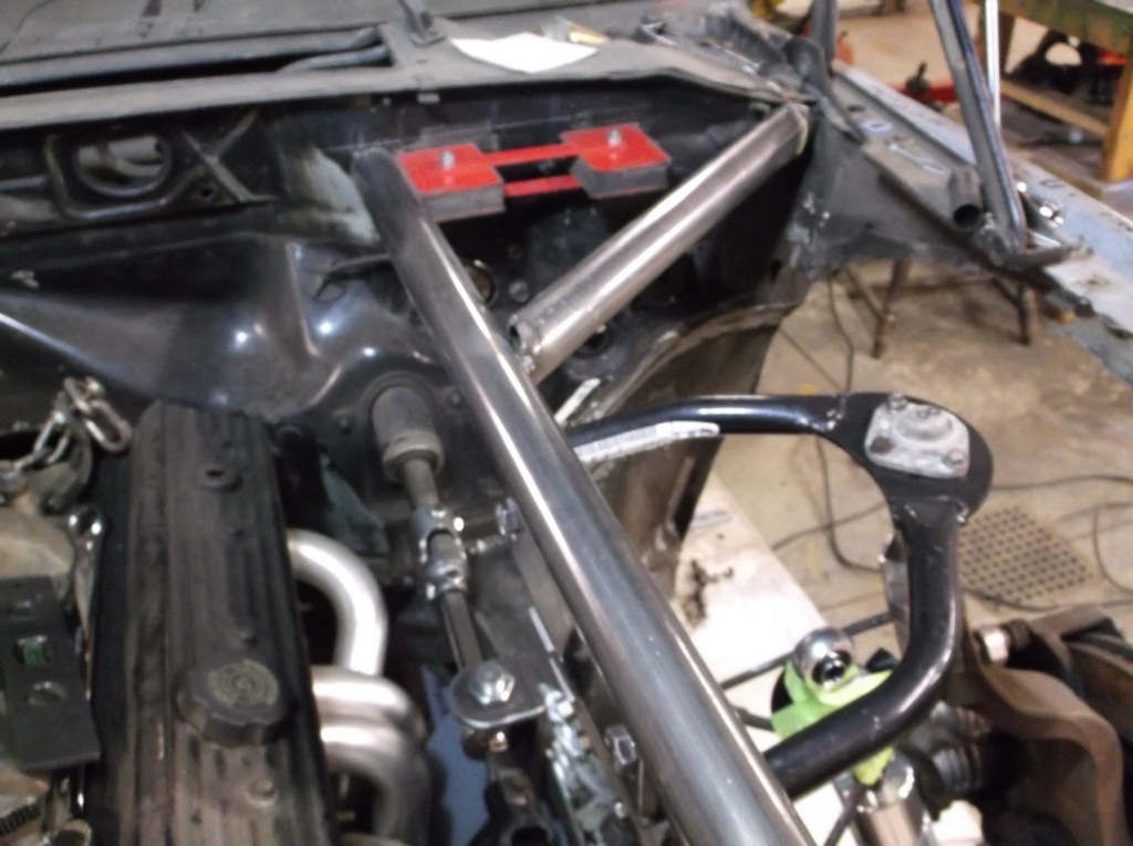
This pic shows tie rod to frame clearance. This would be a hard right turn, full lock, and the suspension in full compression. There is more than 1" betwen the rack extensions and the bottom of the frame rail.
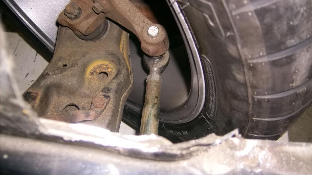
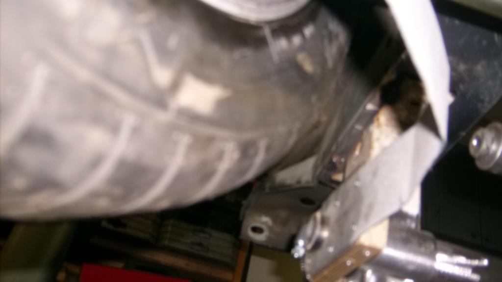
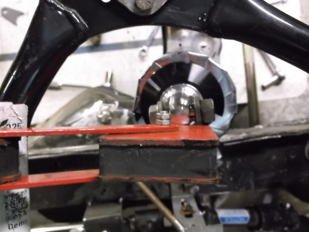
The other concern I had was rack and sway bar clearance in the odd scenario of full turn to lock and the suspension compressed on the same side. Usually a hard left turn would cause the body to lift on the left side which would increase the clearance between the sway bar arm and the rack extension. However if for some reason the suspension would go into compression for whatever reason (inside rumble strip, debris on the road or track) I wouldn't want any contact that might restrict or lock the steering.
Here is what I got at full left turn and full compression.
I think I will be OK even with a straight sway bar arm.
I also checked for camber gain. That was one of the primary factors in wanting to convert to a double a-arm suspension in the first place. Regardless of the initial static camber setting i measured a consistent 1 1/2* gain in negative camber thru 3" of compression. The gain was very linear at about 1/2 degree per inch of travel. I also checked for camber loss when the suspension drops and was very surprised that there is none. My -5/8* camber was consistent through 2 1/2 inches of drop.
here is a pic of the upper ball joint at 3" compression (up travel). It clears the under side of the stick fiberglass hood by about 1/2".

This pic shows tie rod to frame clearance. This would be a hard right turn, full lock, and the suspension in full compression. There is more than 1" betwen the rack extensions and the bottom of the frame rail.

The other concern I had was rack and sway bar clearance in the odd scenario of full turn to lock and the suspension compressed on the same side. Usually a hard left turn would cause the body to lift on the left side which would increase the clearance between the sway bar arm and the rack extension. However if for some reason the suspension would go into compression for whatever reason (inside rumble strip, debris on the road or track) I wouldn't want any contact that might restrict or lock the steering.
Here is what I got at full left turn and full compression.


I think I will be OK even with a straight sway bar arm.