
Home brew road racer


Thread Starter
Senior Member

Joined: Aug 2007
Posts: 682
Likes: 45
Re: Home brew road racer
rb85TA thanks for jumping on board the crazy train!!!!!!!
As for the PM about the longer wheelbase it was my solution to the extremely poor weight distribution these cars have. I weighed this car before I started the project and it was a true 60/40 car with 1900lbs on the front wheels and 1308lbs on the rear. Most people would move the engine and trans back 2 to 3 inches. The typical small block and tranny probably weigh 600 to 650lbs. If you round the wheelbase to 100" then you can see that any weight you move front or back becomes a percentage of the distance moved.
650LBS moved 3" rearward = 650lbs x .03 =19.5lbs . Now what you take off the front, adds to the rear, so you would have a total weight shift of 39lbs. That would make my car scale out ar 1861/1347 or about a 58/42 weight distribution.
To get that 39lbs off the front end you would have to make major mods to the firewall and tunnel, shorten the driveshaft, make custom engine and trans mounts and when your all done you've made it harder to work on the engine and ignition.
By moving the front wheels forward, the weight of nearly EVERY part of the car, front or rear, has moved back 5 inches in relation to the front spindle center line. If I figure a conservative 5% of 3000lbs would be 150lbs or a 300lb weight shift. That would make my car a perfect 1600/1600 or 50/50 weight distribution. I don't think I will achieve that but realistically I think I can get 52/48. My engine and trans stay in their stock locations and are easy to service. The firewall stays intact and helps maintain the structural integrity of the car and is better from a fire/safety aspect.
I am not worried about the turning aspect of the car with the longer wheel base. 106" is not long for a car that is 192 inches long. The car will see more
street use and track day time, at a road coarse, than autox, and the longer wheelbase will actually make the car easier to drive at speed as it will not be as twitchy as a shorter wheelbase car.
Moving this front end and making the 4th gen spindles and rack work in the 3rd gen frame was a major undertaking. I put a lot of thought into the pros and cons of doing it as well as running through a few different designs on how to accomplish it. If it works like I hope it will I'll be grinning ear to ear while pushing 1g+ in the corners.
Thread Starter
Senior Member
Joined: Aug 2007
Posts: 682
Likes: 45
Re: Home brew road racer
WOW!!!! 400 post who would have thought?
Any way good news the 383 is together and on the dyno. Because of a problem with the engine that was scheduled ahead of mine we didn't get it on the dyno till late Friday afternoon. We did get it hooked up, started and completed the break in period on the solid, flat tappet cam and seated the rings. The dyno operator is an IHRA racer and had to leave right at 5pm as he had a 4 hour drive to get to the race in Columbus OH. OH well.
The guys have to reinstall the inner valve springs now that the cam is worn in, then reset the valve lash. Once it is all back together they will let it warm up and then drop the hammer. Keep your fingers crossed and hope for big numbers!!! Just last week this shop dyno'd a similar built .030 over 350 engine. It had the same Brodix heads but with smaller runners, 180cc vs mine at 200cc and a slightly smaller cam, .500 lift vs my .540 lift and we are running the same air gap intake manifold. The 350 pulled 427 hp @ 6100rpm ! The shop owner seems pretty confident that mine will pull over 500 hp.
When I started this engine build I was aiming for a reliable 350 to 375 HP out of a 355 hydraulic cam motor with iron heads. Then came the deal on the 200cc brodix heads I found on the Summit Scratch and dent tables. The motor was too small for the heads so I saved my pennies and got the Eagle 383 Pro Street kit. It came with a forged crank and pistons and their 6.00 "I" beam rods rated to 500HP. The shop owner insisted I needed better rods and swapped them out for a set of their "H" beam rods. The set he had on hand even had the ARP2000 bolt upgrade so these are good for 700hp plus.
This is really the only mission creep so far on this project as everything else has been pretty much part of the plan. If the motor makes the big numbers it will cause a ripple effect throughout the rest of the car. The TKO 600 should be adequate but my Centerforce clutch will be close to max. The ZR2 rear axle will need a tru trac for sure along with a solid pinion spacer and a cover girdle. The LS front brakes and the SSBC rear brakes will be fine for the street and autox but if all the ponies pull the carriage too fast on the road course we will have to upgrade the brakes as well.
Member
Joined: Sep 2014
Posts: 474
Likes: 0
From: south central Texas
Car: BUILDING 1985 HARD TOP T/A
Engine: sbc
Transmission: stick
Axle/Gears: GM
Re: Home brew road racer
83RDRACR, THANKS. .. HAHA!
I hear what you're saying. I'm going back about 8" with engine & trans. Along with serious weight reduction program for the nose, altering radiators location, motor plates will also allow me to lower engine /trans ( drysump, so ground clearance not an issue ). The gains will betbetter distribution of weight & less power loss due shorter distance between crank & tires /ground.
Of course, that's what I'm thinking & the chassis shop will tell me what /where I've thought wrong. ..LOL. ultimately, they're going to tell me what I really need to achieve my goals ( they're the pro's & I have full confidence that they know best ).
Luv the build, keep us updated, always interested in how someone else does things & how well it work's
Member
Joined: Sep 2014
Posts: 474
Likes: 0
From: south central Texas
Car: BUILDING 1985 HARD TOP T/A
Engine: sbc
Transmission: stick
Axle/Gears: GM
Re: Home brew road racer
Yeah, I'm sure the 383 will make a bit more than 500hp & you'll absolutely LOVE IT.
Congrats on the thread as well!

Congrats on the thread as well!
Thread Starter
Senior Member
Joined: Aug 2007
Posts: 682
Likes: 45
Re: Home brew road racer
Here it is on the dyno. A little fuzzy from the cell phone.


The dyno pulls are done with huge, 2" primary headers and a 950CFM Holley HP carb. I won't be able to duplicate the numbers they get as the car has 1 5/8 headers and a 750cfm carb.
Member
Joined: Sep 2014
Posts: 474
Likes: 0
From: south central Texas
Car: BUILDING 1985 HARD TOP T/A
Engine: sbc
Transmission: stick
Axle/Gears: GM
Re: Home brew road racer
Well, I'm sure that someone makes a set of headers that size but I don't know who. Doug's makes a set of 1.75" primary tube long headers for sure. The 750 will work fine, but if it's making more with the 950 ( that's really big for a street 383), then you can always upgrade later.
What did she do (power, tq.), on the dyno?
What did she do (power, tq.), on the dyno?
Thread Starter
Senior Member
Joined: Aug 2007
Posts: 682
Likes: 45
Re: Home brew road racer
Well, I'm sure that someone makes a set of headers that size but I don't know who. Doug's makes a set of 1.75" primary tube long headers for sure. The 750 will work fine, but if it's making more with the 950 ( that's really big for a street 383), then you can always upgrade later.
What did she do (power, tq.), on the dyno?
What did she do (power, tq.), on the dyno?
Adapter flange
http://www.summitracing.com/oh/parts...1hkr/overview/
headers like these:
http://www.summitracing.com/oh/parts/sch-1616s
Anyway, The motor fell a little short of expectations. The dual plain air gap couldn' t flow enough air above 5500-5600 rpm so the horsepower pretty much leveled off there at 455hp and stayed there through 6100 rpm. We ran a pull through 6500 rpm and HP dropped to 435 and TQ was 352. It is a torque monster though with peak torque of 472 @ 4300, 450lb/ft @ 4900 and still over 400lb/ft at 5900 rpm. We tried a 1" spacer under the carb thinking the added volume would let it pull higher into the rpm range but all it did was raise the power band about 500 rpm, 454hp, 397lb/ft @ 6000rpm. The dyno guys said a single plane air gap would have pulled past 6000rpm and got us closer to the 500hp number.
The 750cfm carb I have is a model 3310 vacuum secondary. I have had this carb for a few years and no matter what engine it has been on (mostly mild 350's) and how the primary's were jetted it ran very rich. I thought it was because the carb was just too big for the motors. Thinking it would work better on the 383 I had the dyno guys run a few pulls with this carb. It ran very rich, 11.5:1 A/F ratio!!!!!! The 900cfm race carb was a dead on 13.5 to 14.2 A/F.
We dropped the primary jet from a 71 to a 68 and ran it again but the A/F only got to 11.9. The best dyno numbers for this card were 425hp @ 5500 and 439lb/ft @4400. This was with the spacer installed.
This carb has a metering plate in it with a fixed orifice. Given that it is a vacuum secondary carb I assumed (there is that bad word again) it would be a fairly conservative jet size since these carbs are not usually used on all out race motors. Was I surprised to find on Holley's web site that the orifice on this carb is .081 or a #74 Holley jet. The next smaller plate is .073 or a #70 jet. They offer a few smaller sizes as well. I could get one of the smaller ones and gradually drill it out till I get favorable A/F readings on the wideband O2 I'll be running. Better sollution would be to convert the secondary side to a real metering block that uses real jets, add jet extensions to control fuel slosh and make it more tuneable.
But the motor is home and I have some good data to work with to try and make it a little better. A big relief is to know that the motor will safely run up to 6500rpm or more and that the ignition and valve train were steady at those speeds. Overall I am very happy how it turned out and can't wait to get this in the car and running under its own power again.
Just one more incentive to get back out into the garage and get it finished.
Member
Joined: Sep 2014
Posts: 474
Likes: 0
From: south central Texas
Car: BUILDING 1985 HARD TOP T/A
Engine: sbc
Transmission: stick
Axle/Gears: GM
Re: Home brew road racer
Wow, I didn't think that the air gap dual plan would hurt it that bad. But, hell if you're happy with it. .. then run it.
As far as the headers, I know that summit sells Doug's headers and you can get a set of 1.75"(1 3/4), primary tube long tube headers for a std. Svc 23* head, about $630.00
As far as the headers, I know that summit sells Doug's headers and you can get a set of 1.75"(1 3/4), primary tube long tube headers for a std. Svc 23* head, about $630.00
Thread Starter
Senior Member
Joined: Aug 2007
Posts: 682
Likes: 45
Re: Home brew road racer
Wow, I didn't think that the air gap dual plan would hurt it that bad. But, hell if you're happy with it. .. then run it.
As far as the headers, I know that summit sells Doug's headers and you can get a set of 1.75"(1 3/4), primary tube long tube headers for a std. Svc 23* head, about $630.00
As far as the headers, I know that summit sells Doug's headers and you can get a set of 1.75"(1 3/4), primary tube long tube headers for a std. Svc 23* head, about $630.00
http://www.summitracing.com/oh/parts/pfs-52026
For the headers again I will use what I have and upgrade as needed. With the torque this motor is making I could easily go 1 3/4" primaries and if money allowed, a stepped header like you mentioned. Getting it on the road will tell me what it needs.
Member
Joined: Sep 2014
Posts: 474
Likes: 0
From: south central Texas
Car: BUILDING 1985 HARD TOP T/A
Engine: sbc
Transmission: stick
Axle/Gears: GM
Re: Home brew road racer
Right on! Yeah, just had a bomb dropped on my head! I'm a truck driver in the oilfield (Texas ), & my company just got told that when we finish the job we're on.... we're gone! That's tomorrow btw, so I don't know if I'll even have a job after tomorrow.
My project. ... a stack of parts & the car isn't even in the same location as they are, Arrrgggh ! LOL, gotta laugh... to keep from crying ������
My project. ... a stack of parts & the car isn't even in the same location as they are, Arrrgggh ! LOL, gotta laugh... to keep from crying ������
Thread Starter
Senior Member
Joined: Aug 2007
Posts: 682
Likes: 45
Re: Home brew road racer
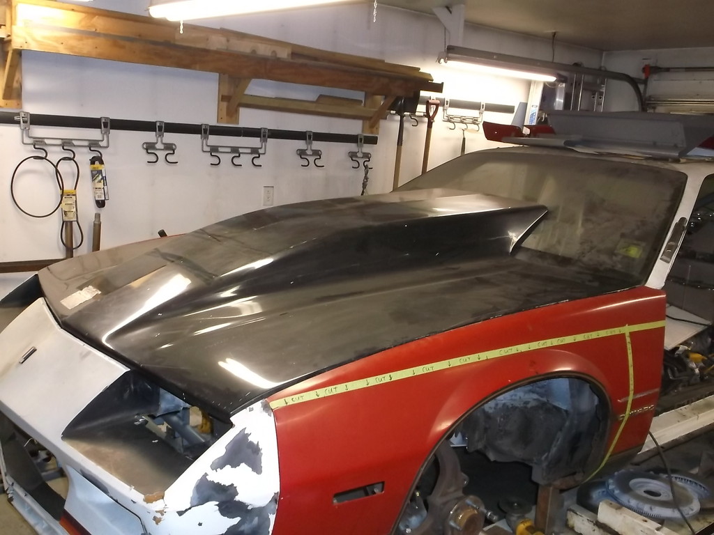
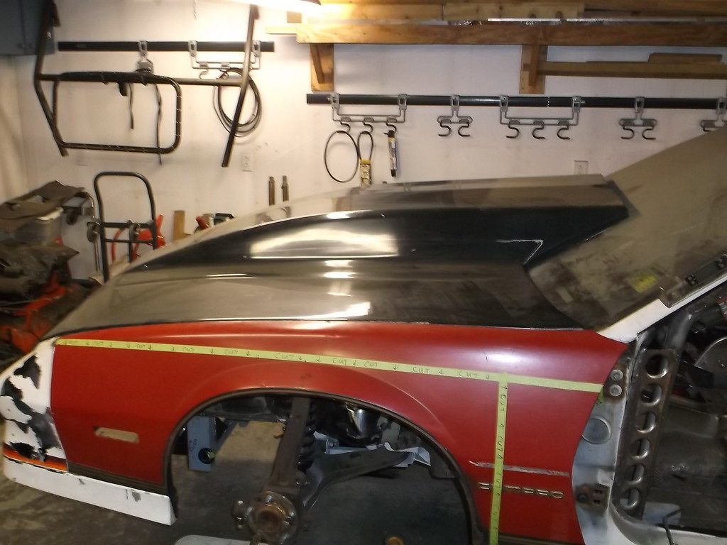
Back to the car now. I must be making some progress as I was actually fitting up the fenders, hood and front fascia the other night. That is a whole lot different/easier than building a front suspension from scratch!!!!!!.
The fenders and fascia are OE pieces but modified (why should they be different from the rest of the car?) and the hood will be made from a Harwood 6" pin-on cowl hood that I picked up several years ago. I am going to cut the cowl scoop down as low as I can get it but will need to get the new motor bolted in to see what it needs to clear the carb and air cleaner. Hopefully I can cut it down to 3" or less. With the hood on it got me to rethinking how I was going to vent the air from under the hood.
I had originally planned to run louvers on both sides of the cowl scoop similar to a Viper, to vent the air from under the hood. After looking at several post about air extraction hoods I am leaning more towards a single louvered vent in the front of the cowl scoop similar to the one Blacktopking made for the war bird (A great car and build thread).
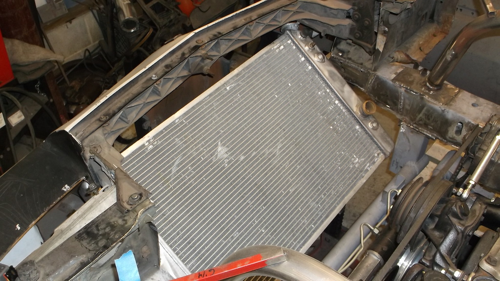
My radiator is angled forward almost 45* and will have a pair of electric fans mounted on top so any air exiting the radiator will be blowing up towards the underside of the hood.
I have also been tossing around the idea of adding an x-brace at the front of the frame to tie in the upper rails to the lower cross member. It just seems really open and could invite twist or flex there.
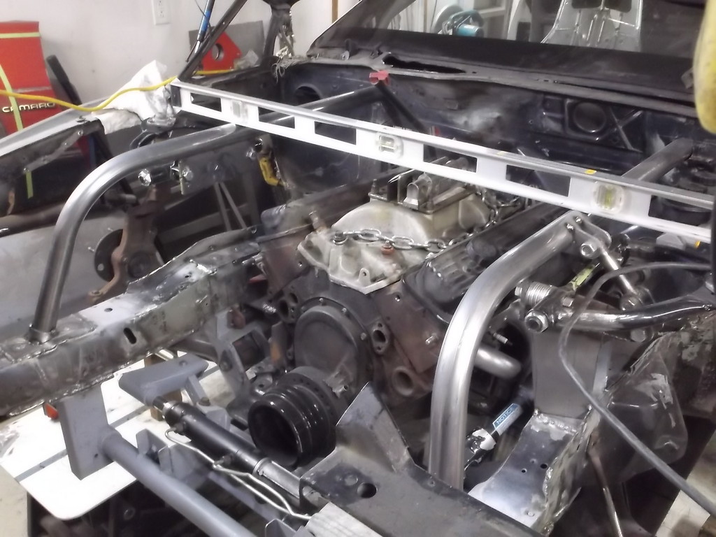
X brace placement
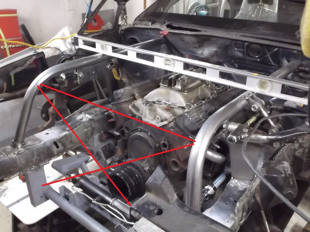
The x brace would probably be made from 1" square tubing .090 wall because that is what I have on hand. It would also have to be removable, so a bolt in design. To help direct the air from the radiator to the extractor vent I would want to attach a piece of aluminum sheet to the x-brace. this would block most of the air from washing over or around the engine. I would also enclose the sides from radiator core to x-brace and possibly partially enclose the top leaving an opening just below the extractor vent.
Not to let a large flat panel go to waste I was thinking I could mount my radiator recovery tank, the p/s reservoir, and the remote oil filter on to the aluminum sheet on the x-brace.
This would be a lot more work. I think the x-brace would help the frame and I like the idea of having someplace up front to mount the two tanks and the oil filter. Any opinions on this? I want to get this thing off the ramps and cleaned and painted so I have got to get the engine bay done soon.
The fenders and fascia are OE pieces but modified (why should they be different from the rest of the car?) and the hood will be made from a Harwood 6" pin-on cowl hood that I picked up several years ago. I am going to cut the cowl scoop down as low as I can get it but will need to get the new motor bolted in to see what it needs to clear the carb and air cleaner. Hopefully I can cut it down to 3" or less. With the hood on it got me to rethinking how I was going to vent the air from under the hood.
I had originally planned to run louvers on both sides of the cowl scoop similar to a Viper, to vent the air from under the hood. After looking at several post about air extraction hoods I am leaning more towards a single louvered vent in the front of the cowl scoop similar to the one Blacktopking made for the war bird (A great car and build thread).
My radiator is angled forward almost 45* and will have a pair of electric fans mounted on top so any air exiting the radiator will be blowing up towards the underside of the hood.

I have also been tossing around the idea of adding an x-brace at the front of the frame to tie in the upper rails to the lower cross member. It just seems really open and could invite twist or flex there.

X brace placement

The x brace would probably be made from 1" square tubing .090 wall because that is what I have on hand. It would also have to be removable, so a bolt in design. To help direct the air from the radiator to the extractor vent I would want to attach a piece of aluminum sheet to the x-brace. this would block most of the air from washing over or around the engine. I would also enclose the sides from radiator core to x-brace and possibly partially enclose the top leaving an opening just below the extractor vent.
Not to let a large flat panel go to waste I was thinking I could mount my radiator recovery tank, the p/s reservoir, and the remote oil filter on to the aluminum sheet on the x-brace.
This would be a lot more work. I think the x-brace would help the frame and I like the idea of having someplace up front to mount the two tanks and the oil filter. Any opinions on this? I want to get this thing off the ramps and cleaned and painted so I have got to get the engine bay done soon.
Member
Joined: Sep 2014
Posts: 474
Likes: 0
From: south central Texas
Car: BUILDING 1985 HARD TOP T/A
Engine: sbc
Transmission: stick
Axle/Gears: GM
Re: Home brew road racer
Well, sorry for dismal post as to my unfortunate situation. ... it has nothing to do with your thread.
So I'll exit now, good luck with your car.
So I'll exit now, good luck with your car.
Thread Starter
Senior Member
Joined: Aug 2007
Posts: 682
Likes: 45
Re: Home brew road racer
Good luck to you and keep us all posted.
Thread Starter
Senior Member
Joined: Aug 2007
Posts: 682
Likes: 45
Re: Home brew road racer
I picked up some tubing yesterday at the local weld shop. 1" x .125 seamless tubing and a short length of 3/4" x 1.25.. I should have the x-brace finished over the week end and will post pics then.
I keep finding little things that need to be finished up before I can blast and paint the engine compartment and undercarriage. Not sure if I can get it off the ramps before the end of the month.
I keep finding little things that need to be finished up before I can blast and paint the engine compartment and undercarriage. Not sure if I can get it off the ramps before the end of the month.
Thread Starter
Senior Member
Joined: Aug 2007
Posts: 682
Likes: 45
Re: Home brew road racer
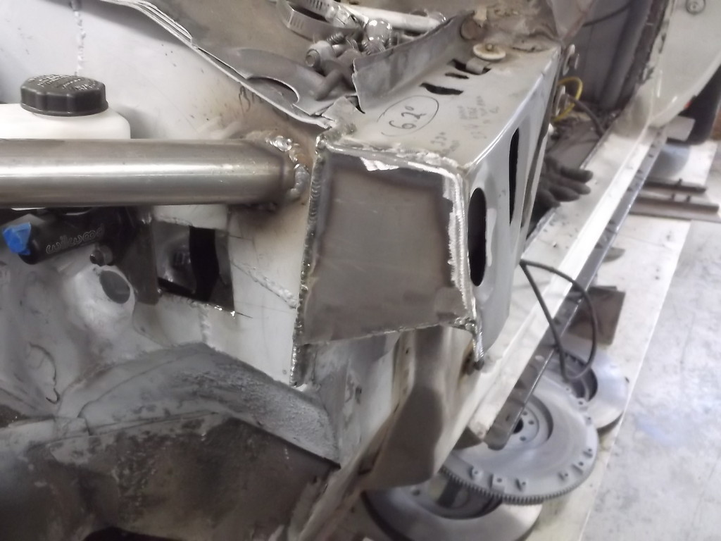
I got most of the x-brace fitted and tack welded in place. The hardest part turned out to be drilling the 3/4" holes in the down legs of the front strut bars. Using a 3/4 hole saw I ended up bending 1 drill bit breaking another and broke 2 teeth off of a brand new hole saw. Oh well $30 worth of broken tools for a couple of holes.
drilled the 3/4 hole thru the tube and pushed 2 1/4 long tubing in.
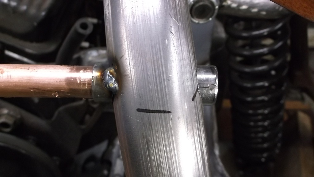
This was the last hole drilled and caused all the tool breakage. That was some serious mis-location on the hole. I was drilling through from the other side when drill bits bent or broke.. I had to relocate to correct position with a high speed rotary file bit.
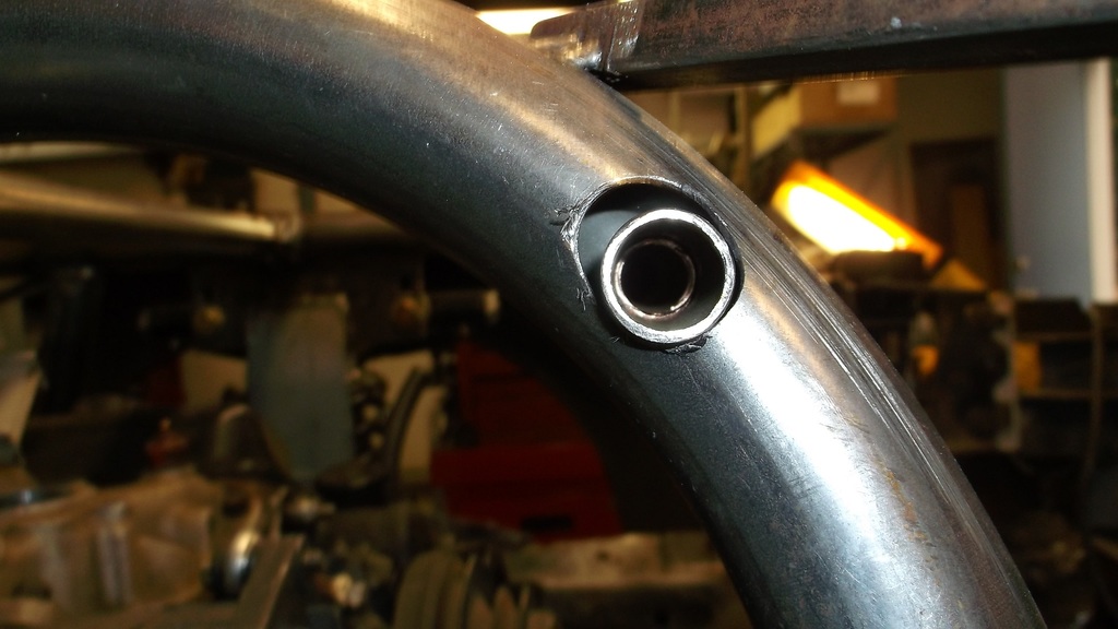
I needed some way to align the two short pieces of tubing and realized that 1/2" copper tubing would press fit inside. With tubes aligned I tacked in place.
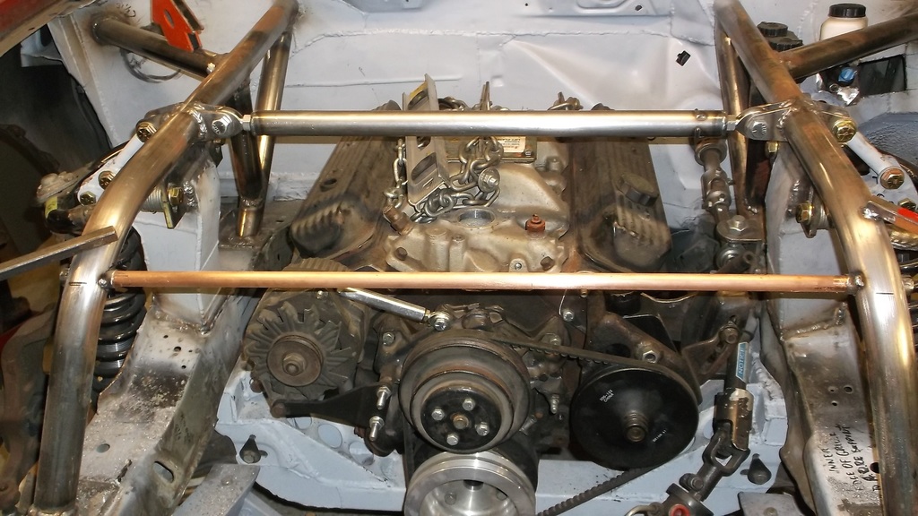
I decided the square tubing I had on hand wouldn't be right for this application and bought some 1" x .125 wall seamless tubing. This gives an ID of 3/4" and allowed me to use QA1 threaded inserts 3/4 od with 1/2-13 threads. With the cross tube bolted in I cut and tack welded the first diagonal which fit really well. Getting the second diagonal to fit tight to the other two tubes was a bit more of a challenge. I ended up taking the brace out of the car and mocking it up on a bench.
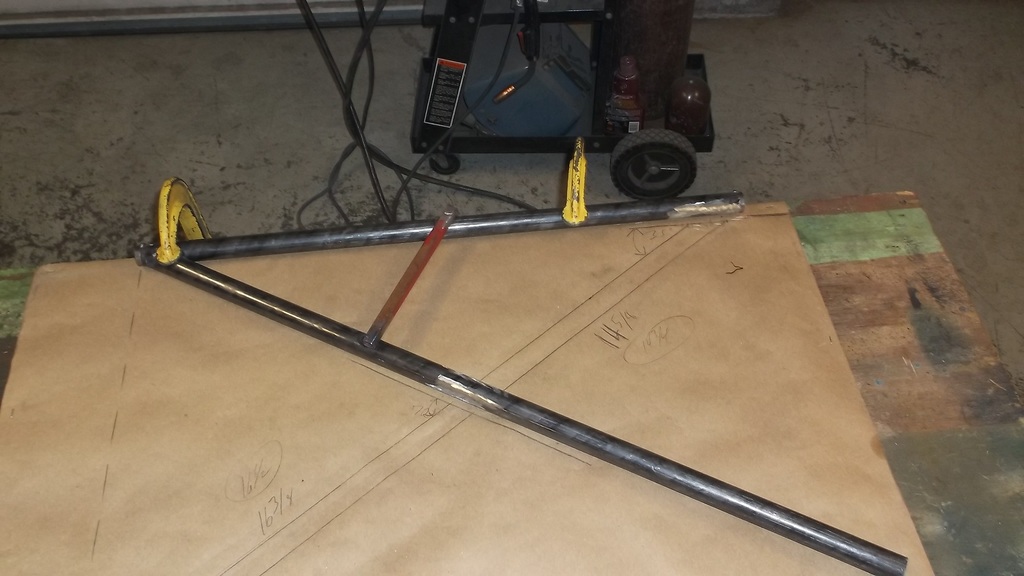
I put a large piece of paper under the brace and traced the tubes. I also added the lower crossmember onto the drawing. Then using a yard stick I drew in the second diagonal brace. With the entire brace drawn onto the paper I removed the tubing and used the drawing as a pattern to cut out the second diagonal brace tubing. It fit great on the first try.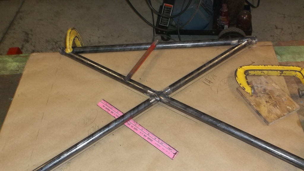
And back in the car.
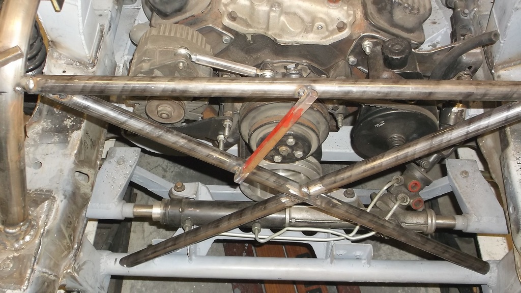
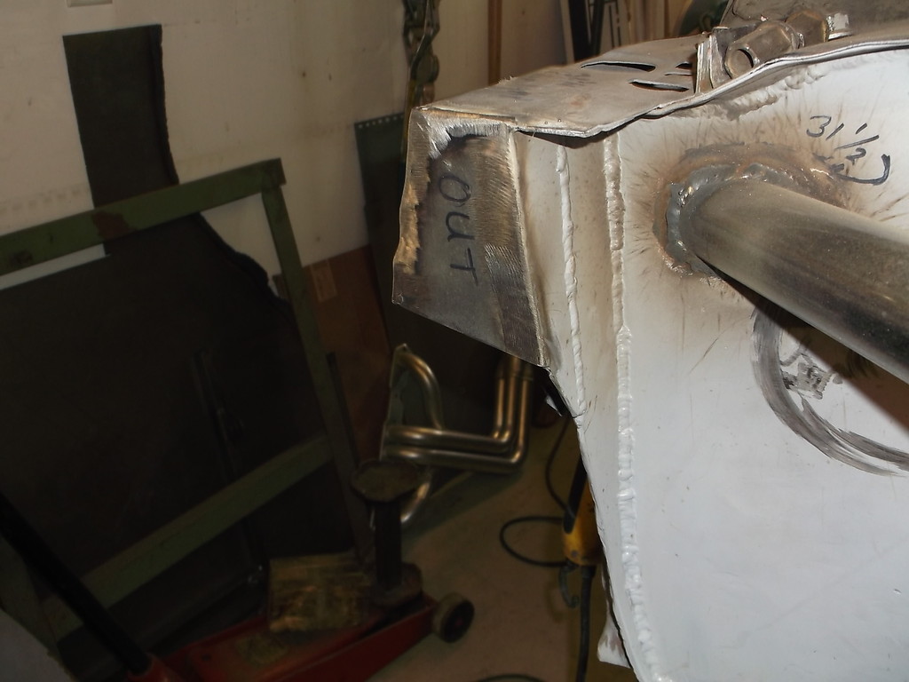
To anchor the bottom of the x-brace I will go with 2, 1/2" solid rod ends, that will bolt to triangular braces of 3/16 or 1/4 plate welded to the lower crossmember. I will pick these up later in the week.
A couple more views
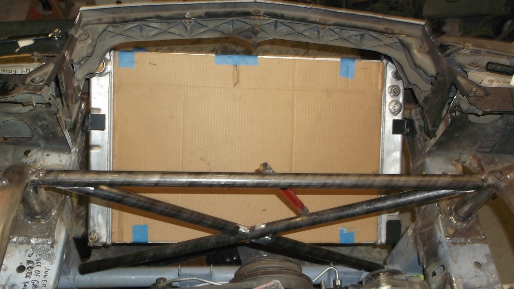
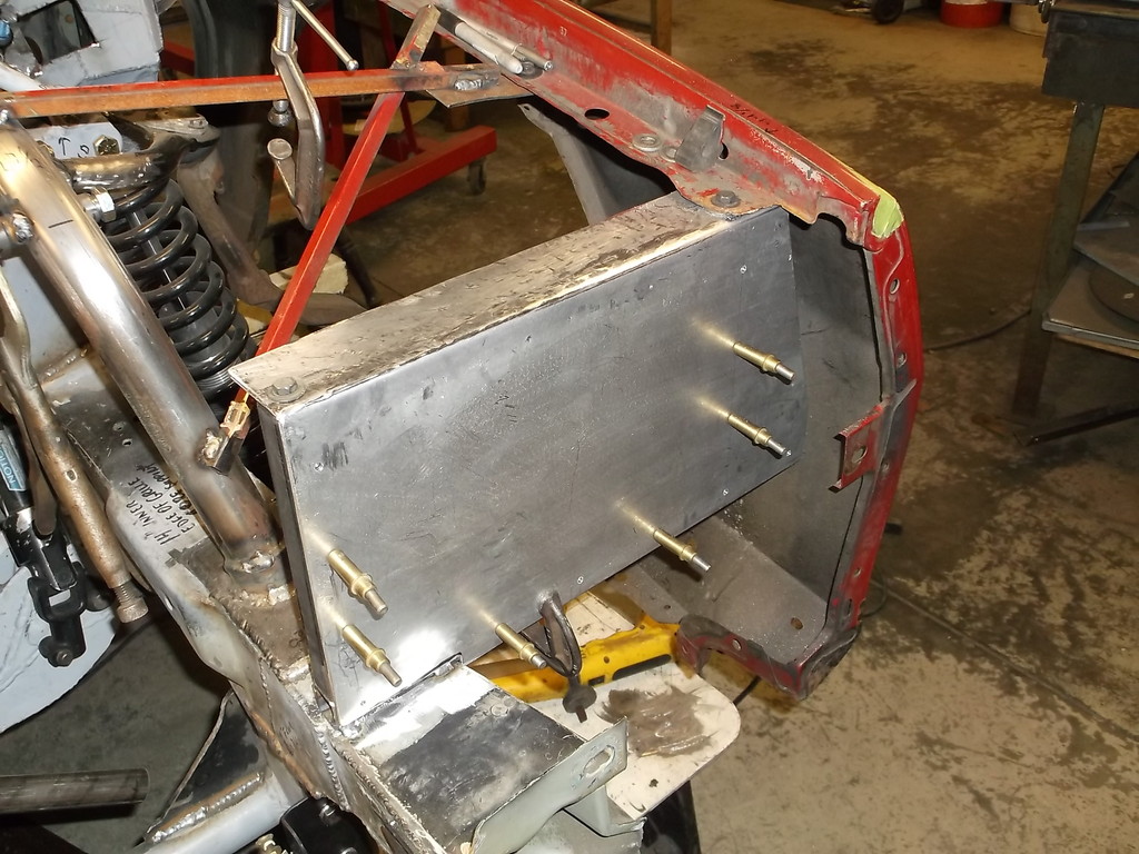
With the brace in place I still have complete access to the front of the engine. Belts, pulleys, water pump, can all be removed with brace in place. The brace will be held in with just 4, 1/2-13 bolts. If I add a full size panel to the front of the brace it will act as an air deflector and direct the air to the bottom of the hood and out the air extraction vent. The panel would also make a convenient place to mount the coolant recovery/fill tank, the remote oil filter, and possibly a P/S reservoir.
drilled the 3/4 hole thru the tube and pushed 2 1/4 long tubing in.

This was the last hole drilled and caused all the tool breakage. That was some serious mis-location on the hole. I was drilling through from the other side when drill bits bent or broke.. I had to relocate to correct position with a high speed rotary file bit.

I needed some way to align the two short pieces of tubing and realized that 1/2" copper tubing would press fit inside. With tubes aligned I tacked in place.

I decided the square tubing I had on hand wouldn't be right for this application and bought some 1" x .125 wall seamless tubing. This gives an ID of 3/4" and allowed me to use QA1 threaded inserts 3/4 od with 1/2-13 threads. With the cross tube bolted in I cut and tack welded the first diagonal which fit really well. Getting the second diagonal to fit tight to the other two tubes was a bit more of a challenge. I ended up taking the brace out of the car and mocking it up on a bench.

I put a large piece of paper under the brace and traced the tubes. I also added the lower crossmember onto the drawing. Then using a yard stick I drew in the second diagonal brace. With the entire brace drawn onto the paper I removed the tubing and used the drawing as a pattern to cut out the second diagonal brace tubing. It fit great on the first try.

And back in the car.

To anchor the bottom of the x-brace I will go with 2, 1/2" solid rod ends, that will bolt to triangular braces of 3/16 or 1/4 plate welded to the lower crossmember. I will pick these up later in the week.
A couple more views


With the brace in place I still have complete access to the front of the engine. Belts, pulleys, water pump, can all be removed with brace in place. The brace will be held in with just 4, 1/2-13 bolts. If I add a full size panel to the front of the brace it will act as an air deflector and direct the air to the bottom of the hood and out the air extraction vent. The panel would also make a convenient place to mount the coolant recovery/fill tank, the remote oil filter, and possibly a P/S reservoir.
Thread Starter
Senior Member
Joined: Aug 2007
Posts: 682
Likes: 45
Re: Home brew road racer
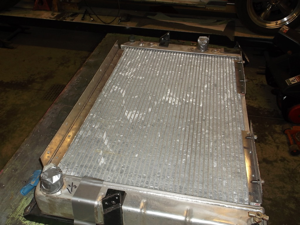
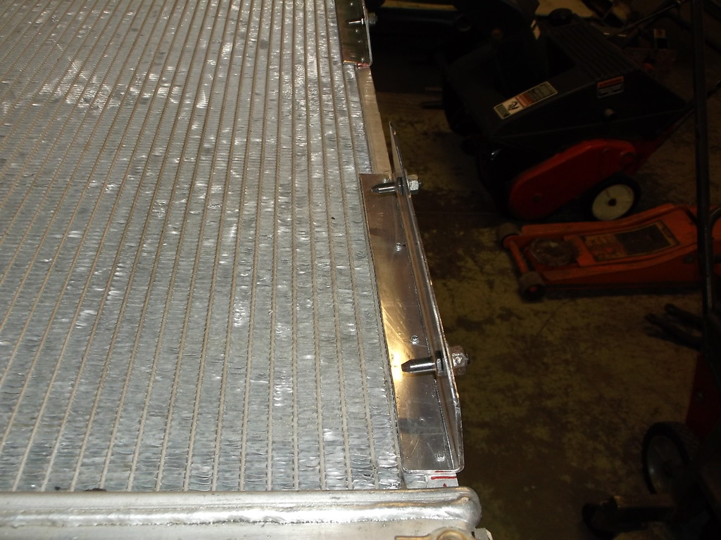
A couple picks of the radiator mounts installed. It is a little hard to see but I added a 1" flange down the side of each mounting bracket to stiffen the brackets and also provide a mounting surface for the aluminum duct work that will channel the air from the grill into the radiator core.


Thread Starter
Senior Member
Joined: Aug 2007
Posts: 682
Likes: 45
Re: Home brew road racer
It was time to remove the rest of the core support so I had to make a new temporary brace for the fender.
with the fender held in place I removed the rest of the core support and made new front fender support and headlight mount from 1" sq. tubing.
I was going to make a complete rectangle out of the tubing, but decided that a piece of 1/8 aluminum sheet would provide the stiffness needed. With it all bolted together there is no noticeable deflection up and down or for and aft.
The aluminum was 6061 grade and was hard as h**l to bend, hence the hammer marks on the top surface.
once both sides were tacked in place I reassembled the front sheet metal to test fit. After a little adjusting of the fenders it all lined up pretty good.
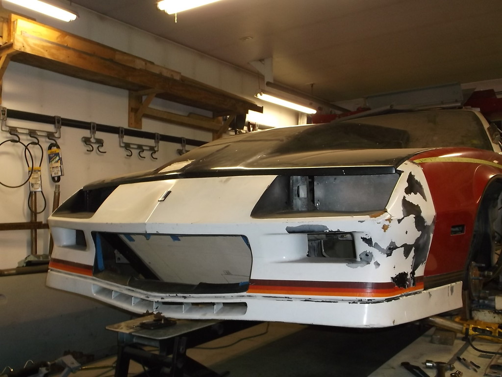
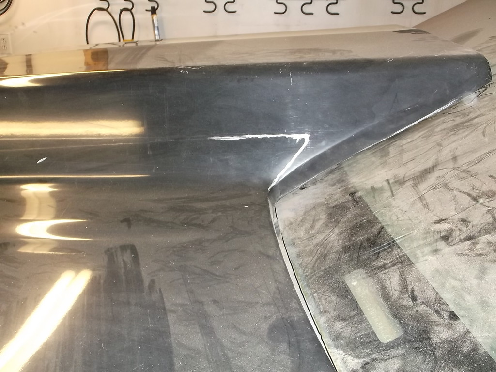
Even banged up, multi colored and loosely fitted together, the look of the front end of of a 3rd gen is just "killer".
here you can see at the back of the cowl hood how much I need to cut it down.
I am trying to finish up the engine compartment so I can get it all painted before the snow flies so I capped off the stub ends of the old upper frame horns.
I've got a few more seams to weld shut and the engine compertment should be good to go. I still need to modify the trans tunnel above the TKO 600 before I can bring it down off the ramps but getting very close now.

with the fender held in place I removed the rest of the core support and made new front fender support and headlight mount from 1" sq. tubing.

I was going to make a complete rectangle out of the tubing, but decided that a piece of 1/8 aluminum sheet would provide the stiffness needed. With it all bolted together there is no noticeable deflection up and down or for and aft.

The aluminum was 6061 grade and was hard as h**l to bend, hence the hammer marks on the top surface.

once both sides were tacked in place I reassembled the front sheet metal to test fit. After a little adjusting of the fenders it all lined up pretty good.


Even banged up, multi colored and loosely fitted together, the look of the front end of of a 3rd gen is just "killer".
here you can see at the back of the cowl hood how much I need to cut it down.


I am trying to finish up the engine compartment so I can get it all painted before the snow flies so I capped off the stub ends of the old upper frame horns.


I've got a few more seams to weld shut and the engine compertment should be good to go. I still need to modify the trans tunnel above the TKO 600 before I can bring it down off the ramps but getting very close now.
Member

Joined: Dec 2013
Posts: 388
Likes: 1
From: Athens, Ohio
Car: 1985 Z28
Engine: Turbo 5.3
Transmission: 4l80e
Axle/Gears: Ford 9"
Re: Home brew road racer
Looking great. I love the look of the 82-84 nose compared to the 85+ nose.
That hood also looks great with it. Wish I could find a nice used pin-on 4-6" cowl hood. I just removed my stock hood again today and lifting that thing is a pain in the a$$.
That hood also looks great with it. Wish I could find a nice used pin-on 4-6" cowl hood. I just removed my stock hood again today and lifting that thing is a pain in the a$$.
Thread Starter
Senior Member
Joined: Aug 2007
Posts: 682
Likes: 45
Re: Home brew road racer
84Lsx, I just sent you a PM about the hood. Please EMAIL me a reply.
Dave
Member
Joined: Dec 2013
Posts: 388
Likes: 1
From: Athens, Ohio
Car: 1985 Z28
Engine: Turbo 5.3
Transmission: 4l80e
Axle/Gears: Ford 9"

Member
iTrader: (2)
Joined: Nov 2006
Posts: 141
Likes: 0
From: Livonia, MI
Car: 1988 IROC-Z
Engine: 355ci SBC, Holley carb
Transmission: 5 speed manual
Axle/Gears: 4th gen Z28
Re: Home brew road racer
Looks great! I love the idea of the radiator in that modified location. Being able to block it off and force the hot air up and out of the extractor hood is very cool. Nice work!
Thread Starter
Senior Member
Joined: Aug 2007
Posts: 682
Likes: 45
Re: Home brew road racer
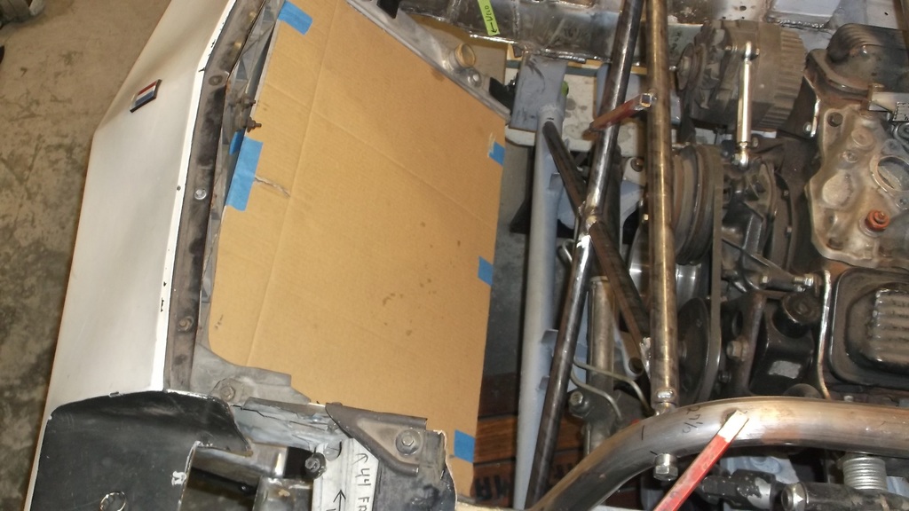
With the wheels moved forward I have lost all of the space behind the headlights where the battery and vapor canisters would set. I don't have the usual places to mount an overflow bottle, p/s reservoir, washer bottle etc. I will use the panel that will bolt to the new x-brace to mount some of these pieces.
X=brace installed....Finally!!!!!!!

Thread Starter
Senior Member
Joined: Aug 2007
Posts: 682
Likes: 45
Re: Home brew road racer
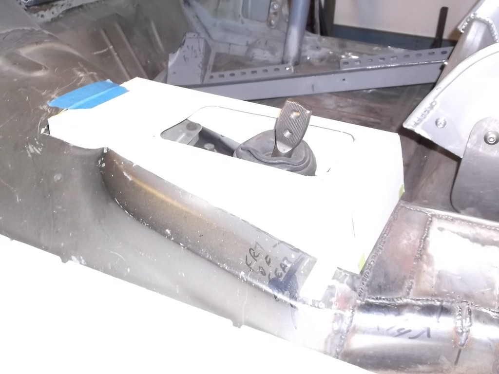
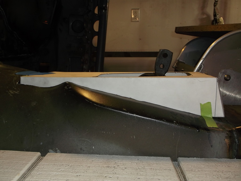
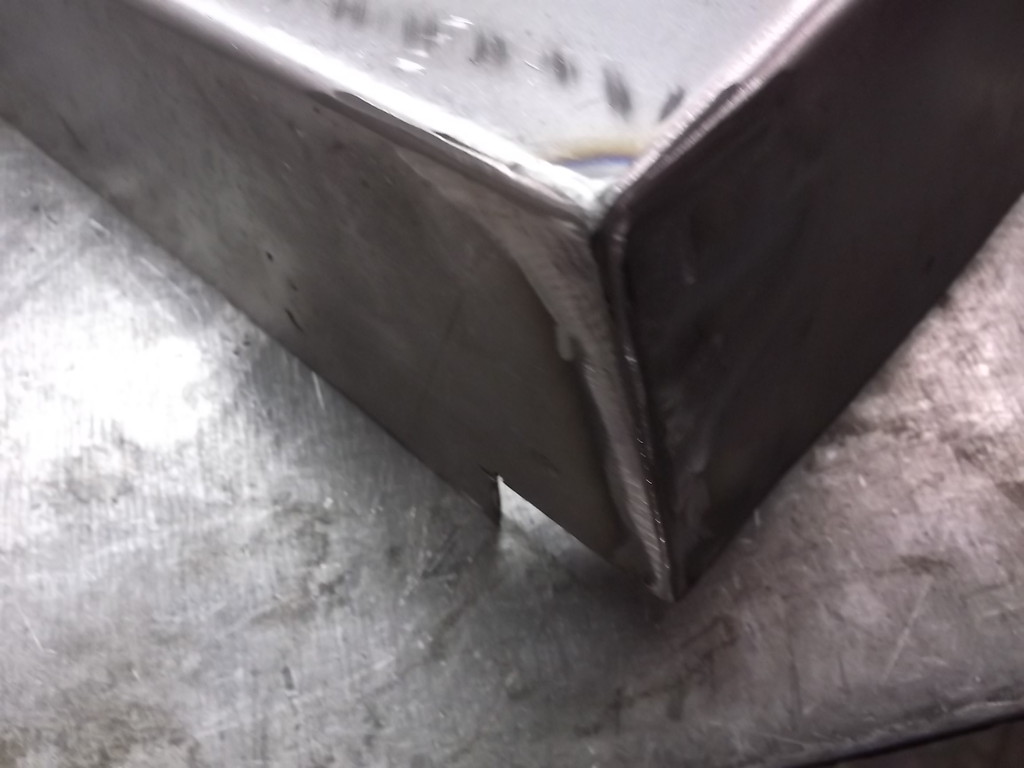
I keep finding things that need to be finished before I can get the car outside to sandblast and paint. With tko 600 extra height at back of trans I had to modify the tunnel.
Poster board template
18ga bent on home made brake press.
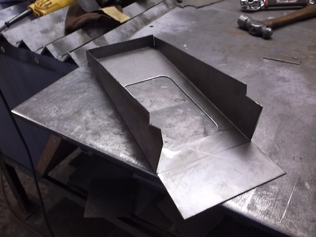
trial fit
welded corners
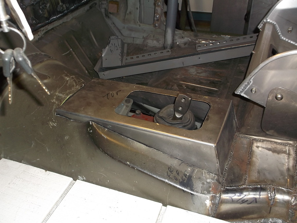
All welded in
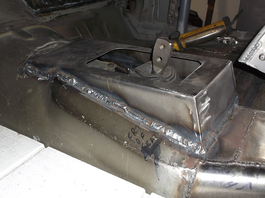
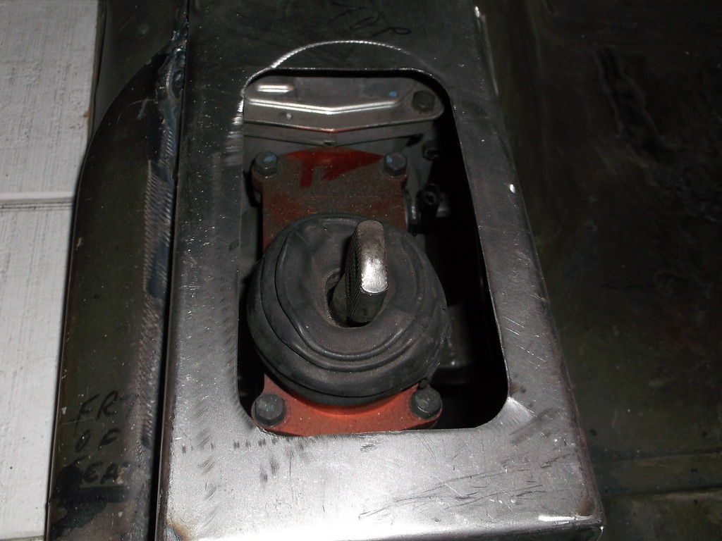
I made the top opening just large enough to get the shifter out. If I need to pull engine/trans together, I can remove shifter plate and bolt on a flat makeshift cover. This will let me pull the engine/trans out the front with only having to slightly tilt them.
Poster board template


18ga bent on home made brake press.

trial fit

welded corners

All welded in


I made the top opening just large enough to get the shifter out. If I need to pull engine/trans together, I can remove shifter plate and bolt on a flat makeshift cover. This will let me pull the engine/trans out the front with only having to slightly tilt them.
Member
Joined: Dec 2013
Posts: 388
Likes: 1
From: Athens, Ohio
Car: 1985 Z28
Engine: Turbo 5.3
Transmission: 4l80e
Axle/Gears: Ford 9"
Re: Home brew road racer
With the side fender supports cut out, how are you attaching your front clip? I'm putting strut bars in from the A-pillar bars and haven't thought of a good way to secure the fenders and front. I see in some previous pictures you just have some quare tubing going to the bolt holes, but I wasn't sure if that was your final design or not.
Thread Starter
Senior Member
Joined: Aug 2007
Posts: 682
Likes: 45
Re: Home brew road racer
With the side fender supports cut out, how are you attaching your front clip? I'm putting strut bars in from the A-pillar bars and haven't thought of a good way to secure the fenders and front. I see in some previous pictures you just have some quare tubing going to the bolt holes, but I wasn't sure if that was your final design or not.
The square tubing in the previous post were temporary, needed to hold the front of the fender in place while I cut out what was left of the core support behind the headlights and replaced it with the square tubing and aluminum sheet. I will be adding a similar fender support midway that will probably be made from 3/8 rod or tubing. This will be more for in/out adjustment of the fender and reducing flex at the front and rear mounts than supporting the weight of the fender as the length of the brace will prevent it from supporting much weight.
I haven't yet decided if I am going to run inner fenderwells up front or just some partial splash shields. If I make the fenderwells then they would add support for the fender and front clip.
Thread Starter
Senior Member
Joined: Aug 2007
Posts: 682
Likes: 45
Re: Home brew road racer
With the side fender supports cut out, how are you attaching your front clip? I'm putting strut bars in from the A-pillar bars and haven't thought of a good way to secure the fenders and front. I see in some previous pictures you just have some quare tubing going to the bolt holes, but I wasn't sure if that was your final design or not.

and front view.

Thread Starter
Senior Member
Joined: Aug 2007
Posts: 682
Likes: 45
Re: Home brew road racer
I haven't posted for the last 4 weeks. I got roped into a wood working project by my daughter for my granddaughter. She asked to make a toy box for a silent auction for their annual school fundraiser. I am no carpenter let alone a furniture maker but it was for my granddaughter, how could I say no.
Its a simple design made from 2 sheets of 5/8 plywood, a piano hinge and a couple steel handles. It was bad enough that it had to be sanded and stained and made to look like a piece of furniture but then she asked for the school name and logo put on the lid. A few days later she came back and said they wanted all the names of the kids in my granddaughters class and that of their teacher and aide added down the sides. What a project it turned out to be. It gets raffled off tonight so lets hope it brings in a few dollars!!!!!!.
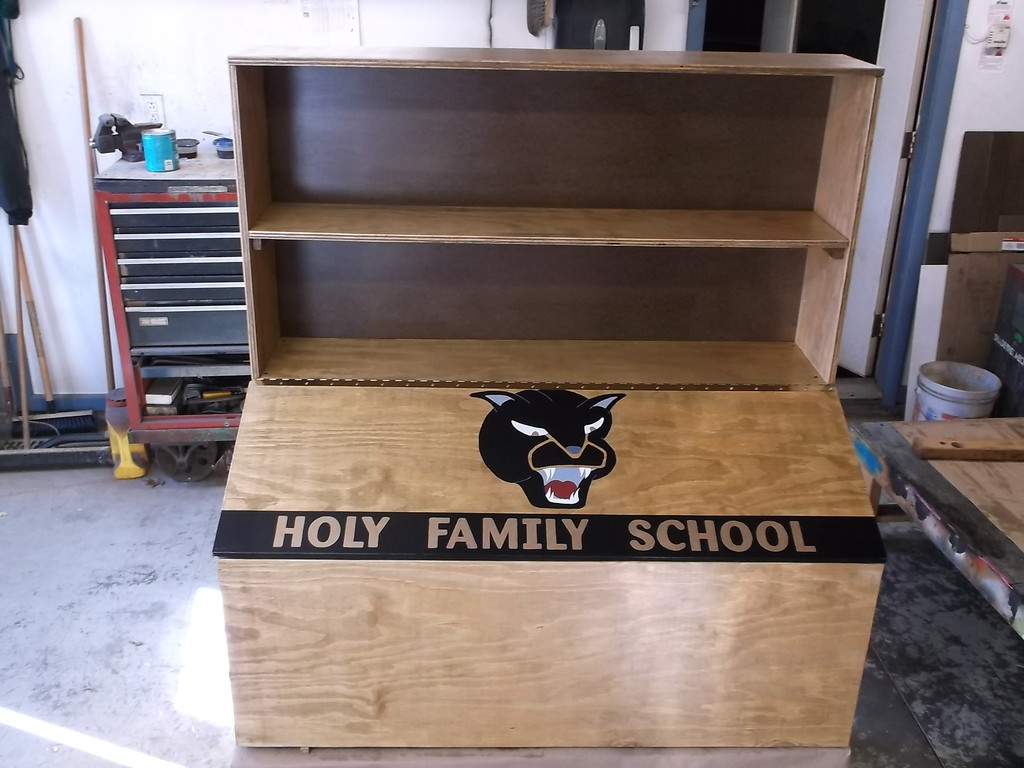
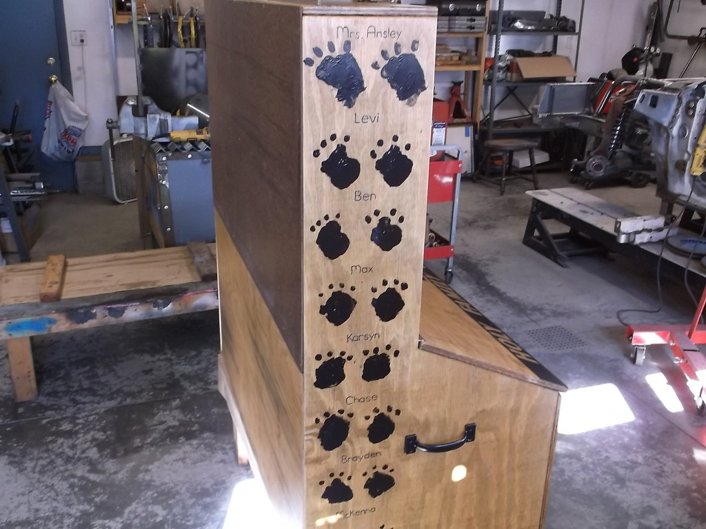
It turned out pretty good, at least I am not embarrased to say I made it. Now I can get back to the Camaro, I think.
Thread Starter
Senior Member
Joined: Aug 2007
Posts: 682
Likes: 45
Re: Home brew road racer
Still no progress on the car. getting the house, yard and vehicles ready for the onset of winter. I have come to the conclusion that 2 cycle snow blowers are the work of the devil.
Thread Starter
Senior Member
Joined: Aug 2007
Posts: 682
Likes: 45
Re: Home brew road racer
Just found this on pro-touring.com. The similarities in the design of the front framework is uncanny. Since the car on the pic is being built buy a professional shop for the Optima Street car challenge, I guess I am not to far off the mark.
http://www.pro-touring.com/attachmen...8&d=1429754301
http://www.pro-touring.com/attachmen...8&d=1429754301

Thread Starter
Senior Member
Joined: Aug 2007
Posts: 682
Likes: 45
Re: Home brew road racer
Just inching along really. doing a little clean up on the front suspension now.
My son changed jobs and had to move 60 miles away. Problem is he still has a house up here full of stuff. I have spent the better part of the last 2 months cleaning it out and moving stuff into a storage unit. Just small things like a jr. sprint car for an 8 to 12 year old, 2 competition go karts, a scag commercial mower, 4 lawn tractors and 5 snow blowers. It wouldn't be so bad but nearly everything needs some type of repair before it can be used or sold. If anyone is interested in anything let me know. I'll send pics and make me an offer.
Besides having to fix all the snow blowers and mowers I have to get his house spruced up before it goes on the market at the end of next week. drywall to fix, rooms to paint, kitchen cabinets to repair etc.
Hopefully once the house is done I can spend a few months working on the Z again and get it plumbed and wired. It is still welded to my ramps but could set down on its wheels with a couple hours work. Since I didn't get it off the ramps to sandblast and paint the undercarriage this past fall I decided to go ahead and wire and plumb the car over the winter getting all the tabs and brackets welded on and do the blasting and painting this coming summer.

Thread Starter
Senior Member
Joined: Aug 2007
Posts: 682
Likes: 45
Re: Home brew road racer
As for the extended wheel base still unsure about how to section the fenders. I was going to just do a big rectangular cut and move it all forward and tack it back in place. The more I look at it though it seems that a better approach might be to cut the front part of the fender, ahead of the wheel opening, at the belt line running above the marker light and then cut around the wheel well and upper flare leaving a 1" flange.
Until I actually have it back on the ground I won't know for sure but right now it looks like the front track width is about an 1" to 1 1/2" wider per side than the rear. The rear tires just tuck up inside the rear quarter panel but the fronts definitely stick out past the edge of the fender lip. I hadn't planned nor do I want to make flares for this so I'll have to see what I've got when its on the ground.
Thread Starter
Senior Member
Joined: Aug 2007
Posts: 682
Likes: 45
Re: Home brew road racer
I am finally back working on the car again!!!!!. I had mentioned in an earlier post that I installed 14" long 400lb/in springs on the front coil overs. They seemed too long and I actually had to make a hydraulic press to compress the springs to get them on the shocks. Well they are too long, the shocks are the same size as the rears and take a 12" spring. Since I couldn't take the old springs back and exchange them I decided to try cutting them down to the correct length.
This is a little trickier than cutting a conventional coil spring as the top and bottom of the spring is milled flat to sit on the threaded adjusters. I marked the spring at 12 1/2" and used my chop saw to cut through the coil. I then used the side of the chop saw blade to grind the bottom edge as flat as possible. I then heated the cut coil and pushed it into the coil above to mimic the shape of the other end of the spring. It took several tries of heating and tweaking the bottom coil to get it to set flat and parallel to the top coil. This was a PITA and totally unnecessary had I bought the correct length to start with.
Pick of shortened spring installed on car.
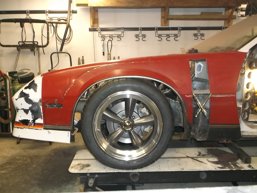
Once the springs were fixed I decided that it was time to get the car back on the ground. It has been setting on metal stands welded to my custom ramps since 12/2010.
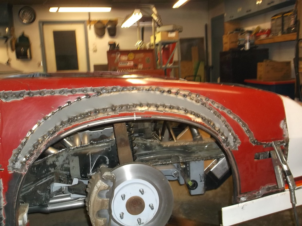
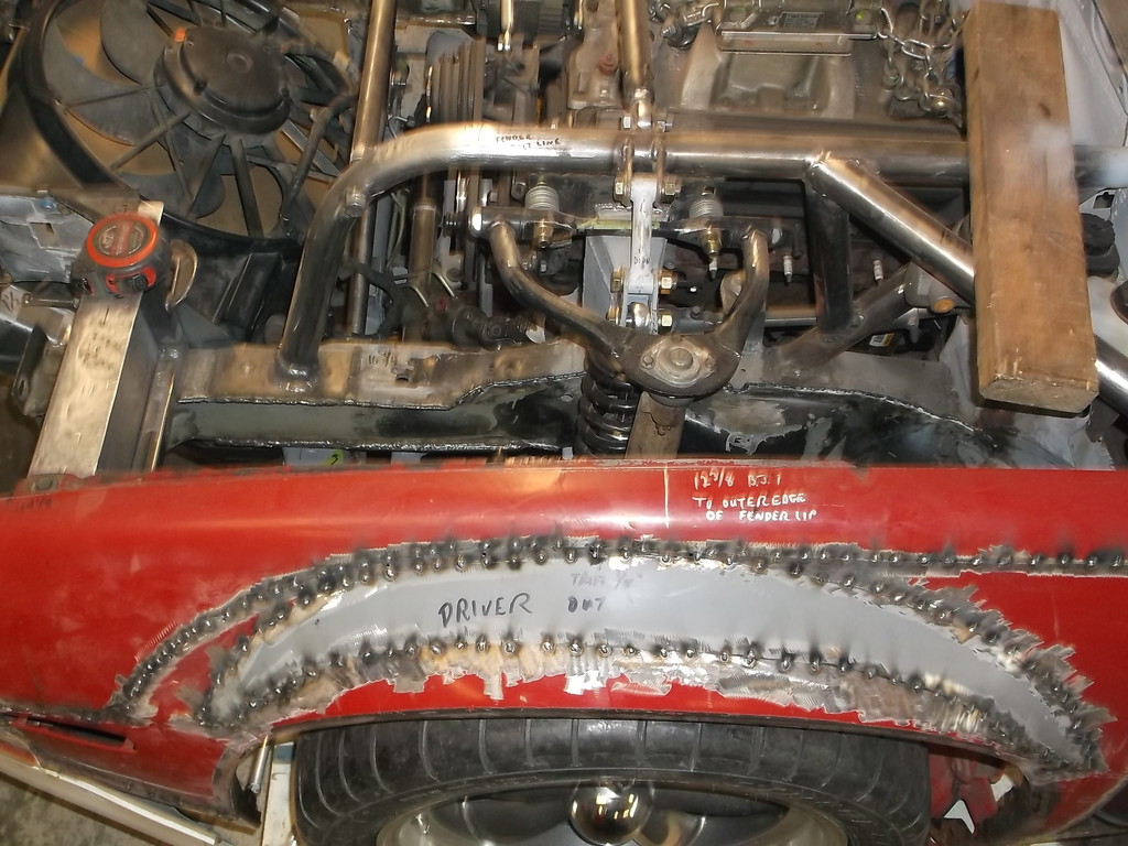
To say that my frame is rigid is an understatement. As I cut away and removed the first stand (LF) that corner of the car did not drop at all. I could slide the stand in and out. I could not force that corner down by standing and jumping on the door sill. I cut the other 3 stands out and lowered the car down onto its 275/40R17 Mickey Thompson UHP radials for the first time.
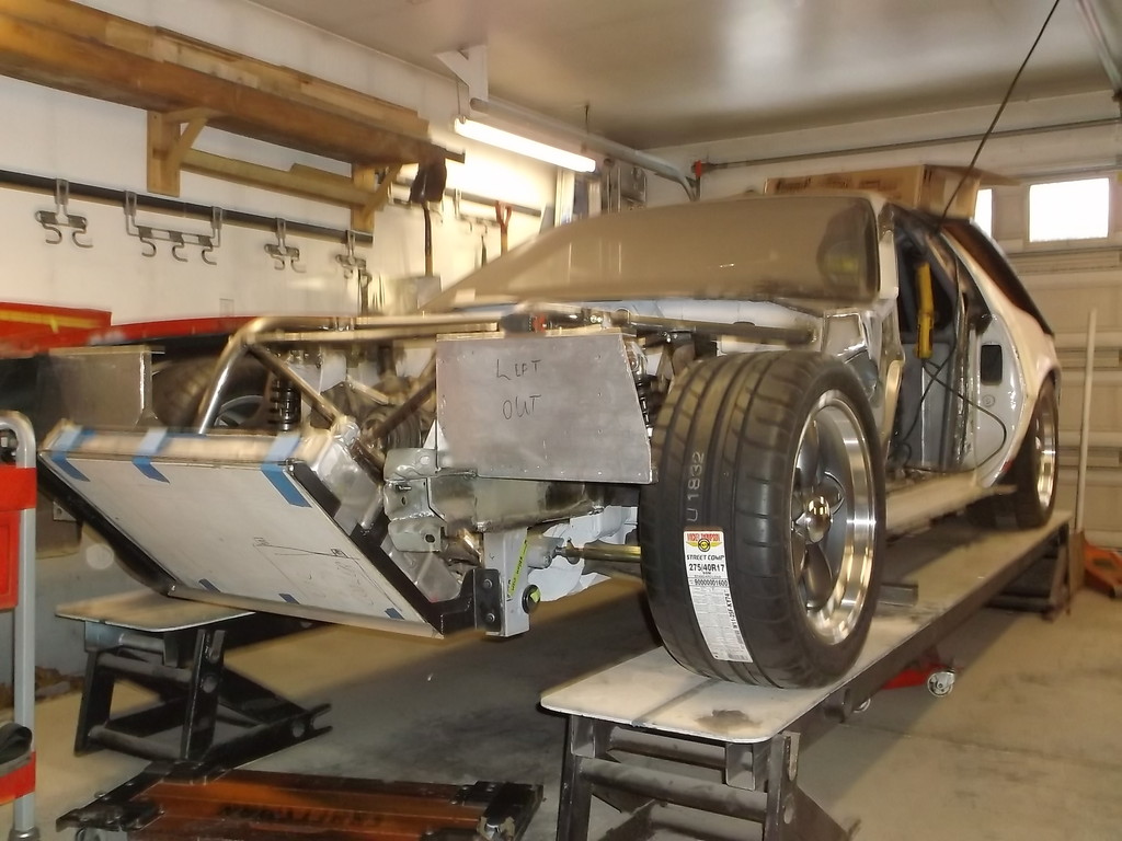
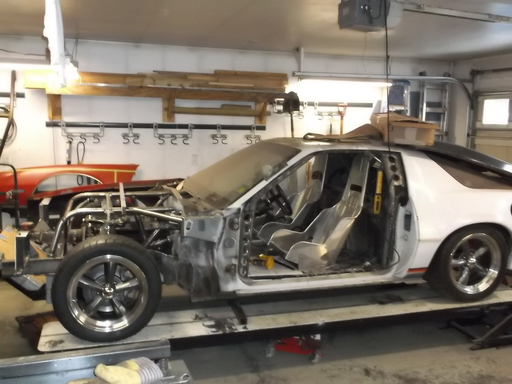
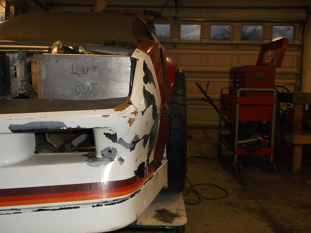
You can see in the first pic that the front tire comes right out to the edge of my ramp while the rear tire does not. Front track width is about 2 1/2" wider than rear. I don't think that will cause any major handling issues but the front tires do extend out past the edge of the fender a good bit.
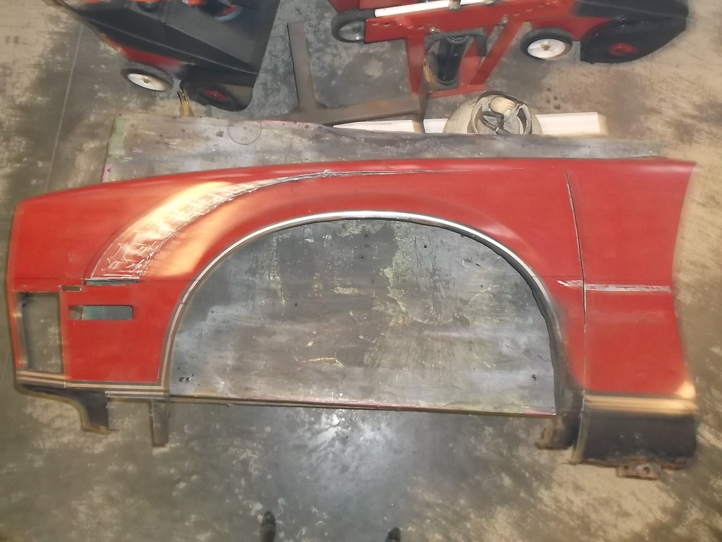
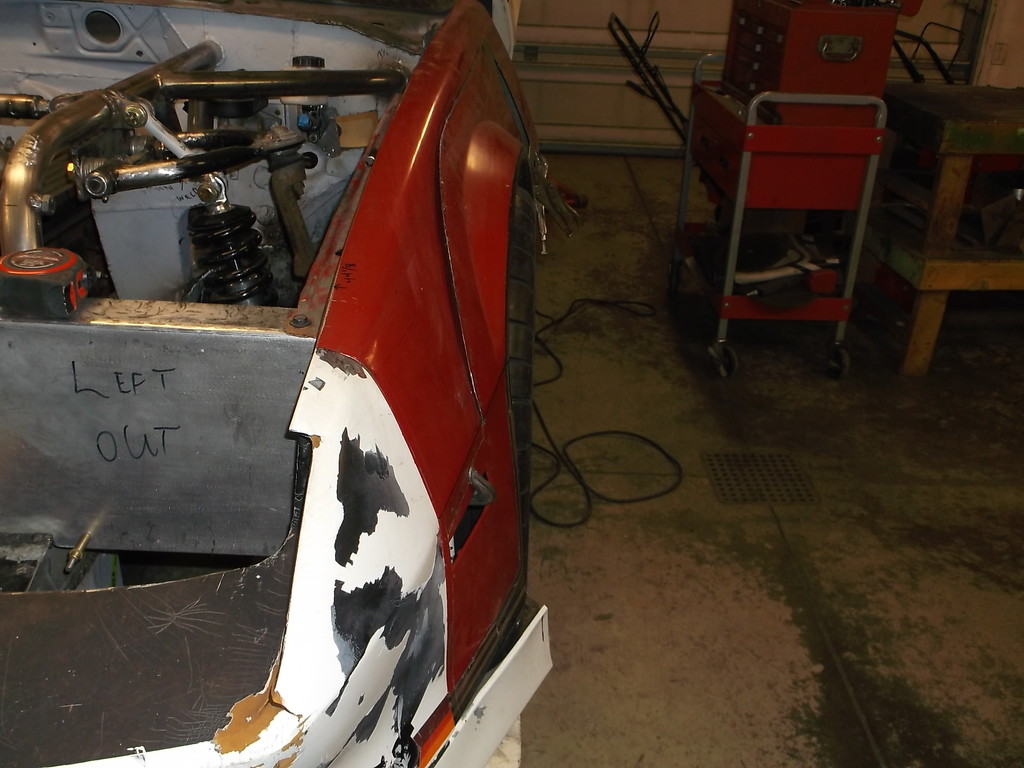
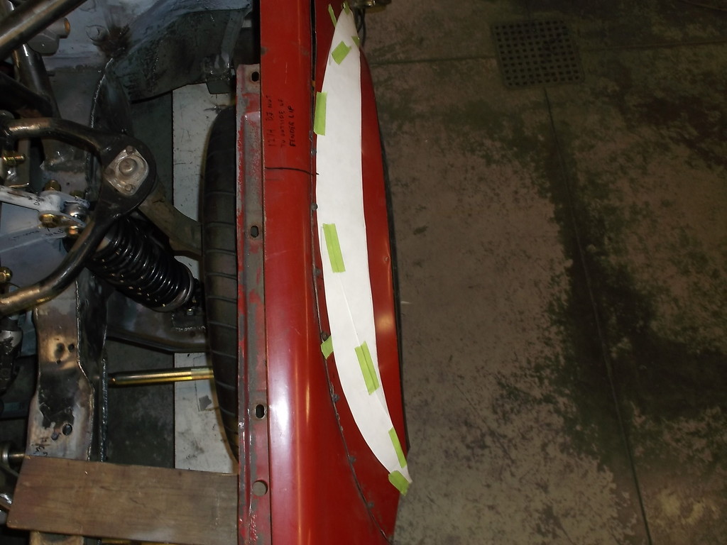
Because the front fenders locate the front valance I had to finally take on the task of chopping up the fender to relocate the wheel opening. I have looked at this dozens of times in the past but never liked the approach. I finally hit on an idea the other day and after drawing it out on the fender and making a few tweaks I held my breath and put cutoff wheel to metal.
This is a little trickier than cutting a conventional coil spring as the top and bottom of the spring is milled flat to sit on the threaded adjusters. I marked the spring at 12 1/2" and used my chop saw to cut through the coil. I then used the side of the chop saw blade to grind the bottom edge as flat as possible. I then heated the cut coil and pushed it into the coil above to mimic the shape of the other end of the spring. It took several tries of heating and tweaking the bottom coil to get it to set flat and parallel to the top coil. This was a PITA and totally unnecessary had I bought the correct length to start with.
Pick of shortened spring installed on car.

Once the springs were fixed I decided that it was time to get the car back on the ground. It has been setting on metal stands welded to my custom ramps since 12/2010.
To say that my frame is rigid is an understatement. As I cut away and removed the first stand (LF) that corner of the car did not drop at all. I could slide the stand in and out. I could not force that corner down by standing and jumping on the door sill. I cut the other 3 stands out and lowered the car down onto its 275/40R17 Mickey Thompson UHP radials for the first time.


You can see in the first pic that the front tire comes right out to the edge of my ramp while the rear tire does not. Front track width is about 2 1/2" wider than rear. I don't think that will cause any major handling issues but the front tires do extend out past the edge of the fender a good bit.
Because the front fenders locate the front valance I had to finally take on the task of chopping up the fender to relocate the wheel opening. I have looked at this dozens of times in the past but never liked the approach. I finally hit on an idea the other day and after drawing it out on the fender and making a few tweaks I held my breath and put cutoff wheel to metal.


Thread Starter
Senior Member
Joined: Aug 2007
Posts: 682
Likes: 45
Re: Home brew road racer
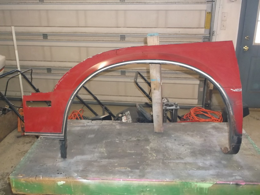
I mounted the fender to the car and slid the wheel opening into place.
I was actually a little surprised by how well it fit up.
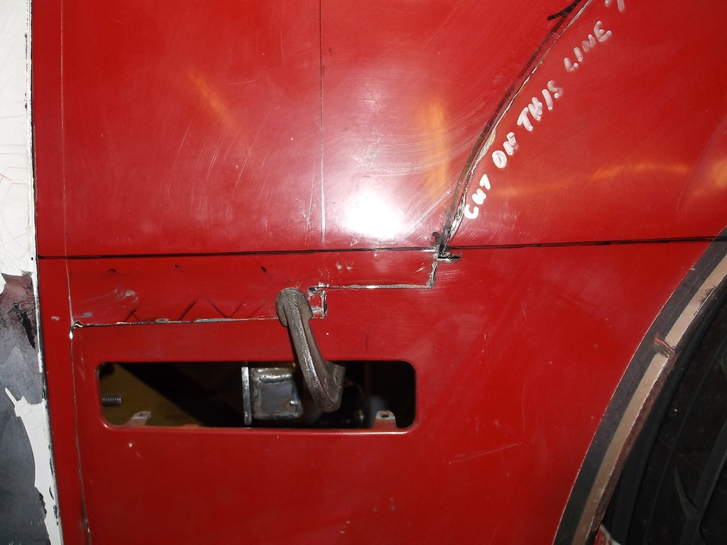
see how stripes align at bottom front of fender.
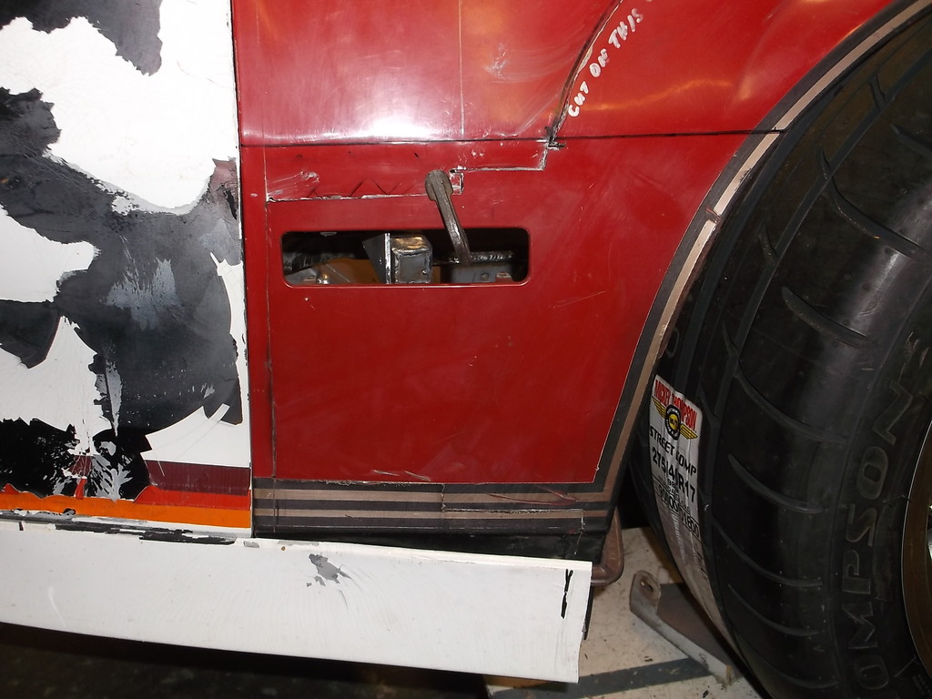
Being able to keep the side marker light keeps the stock look of the fender. If I wouldn't have to modify the wheel flare it would be hard for the casual observer to see that the wheel well had been moved.

Joined: Jun 2000
Posts: 5,364
Likes: 51
From: Enschede, Netherlands
Car: 82 TA 87 IZ L98 88 IZ LB9 88 IZ L98
Engine: 5.7TBI 5,7TPI 5.0TPI, 5,7TPI
Transmission: T5, 700R4, T5, 700R4
Axle/Gears: 3.08, 3.27, 3.45, 3.27
Re: Home brew road racer
That's looking damned good, this thread is quickly becoming one of my favorites.
Thread Starter
Senior Member
Joined: Aug 2007
Posts: 682
Likes: 45
Re: Home brew road racer
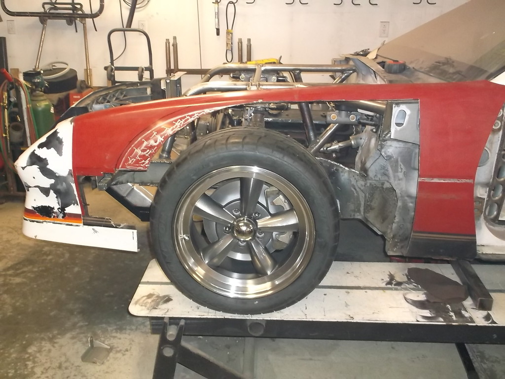
Here is my dilemma with the wider front track. Wheels are 17 x 9 w/ 6" bs.
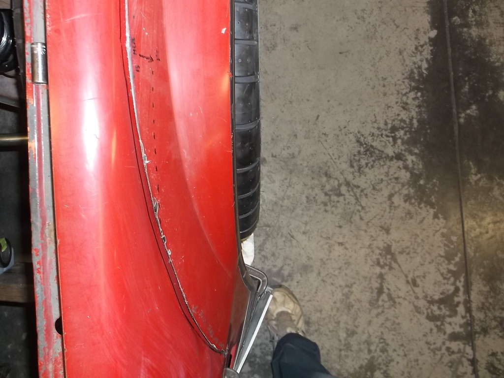
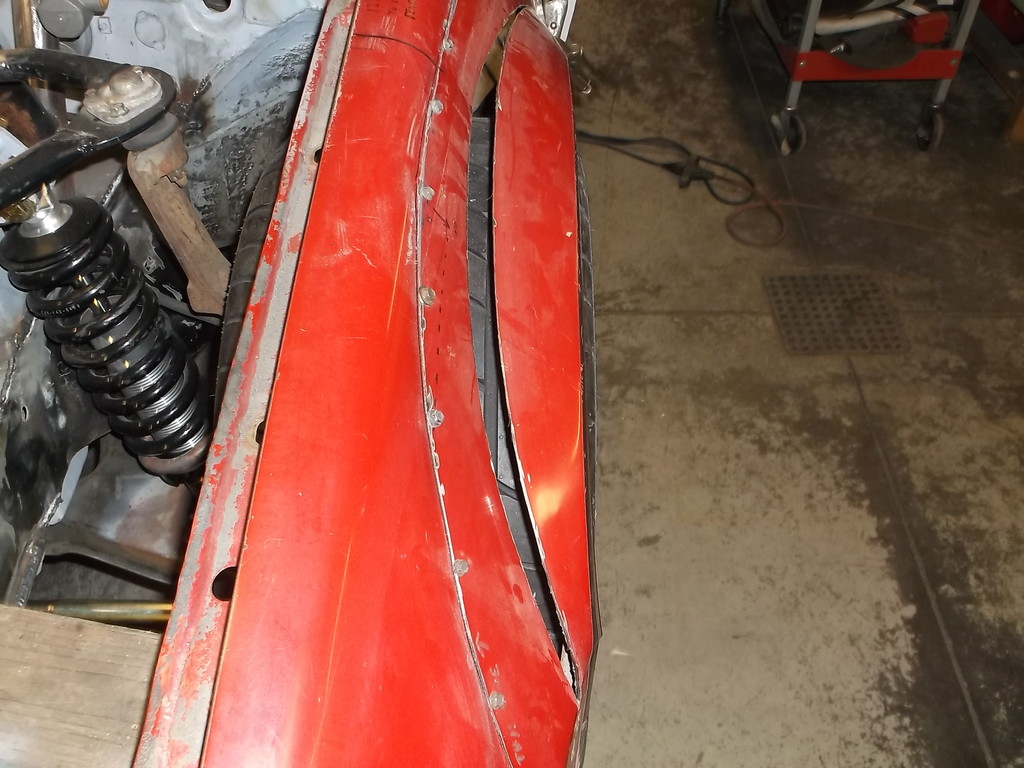
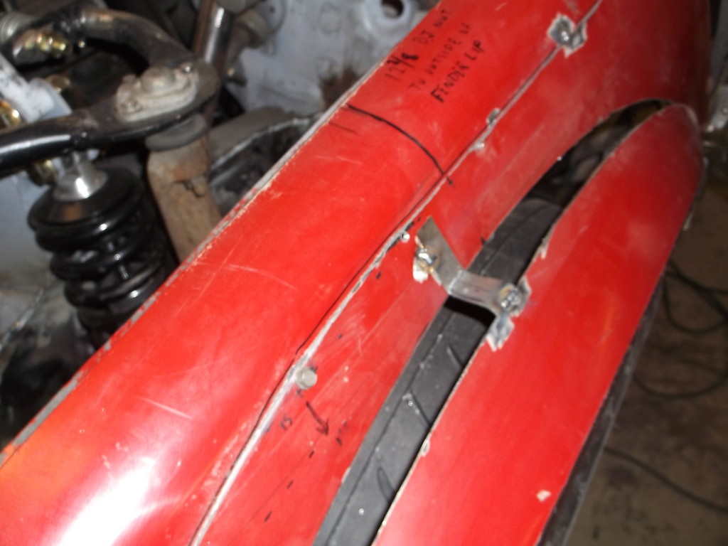
There is room to use a wheel with less back space and move the wheel inward 1 1/2" but I was wanting to run 18 x 10.5 wheels with a 315/30R18 track tire at all 4 corners. That would put the outside of the tire in the same location as now so I have to move the fender out either way. I wanted to keep fender as stock looking as possible and not add some type of generic flare. I decided to see how far out I could push the wheel opening.
By cutting the inside of the wheel lip at the belt line and also at the front of the fender I could get the lower half of the fender out quite a ways.
Looking down from the front
With a little effort I was able to pull the top out as well but still needed more.
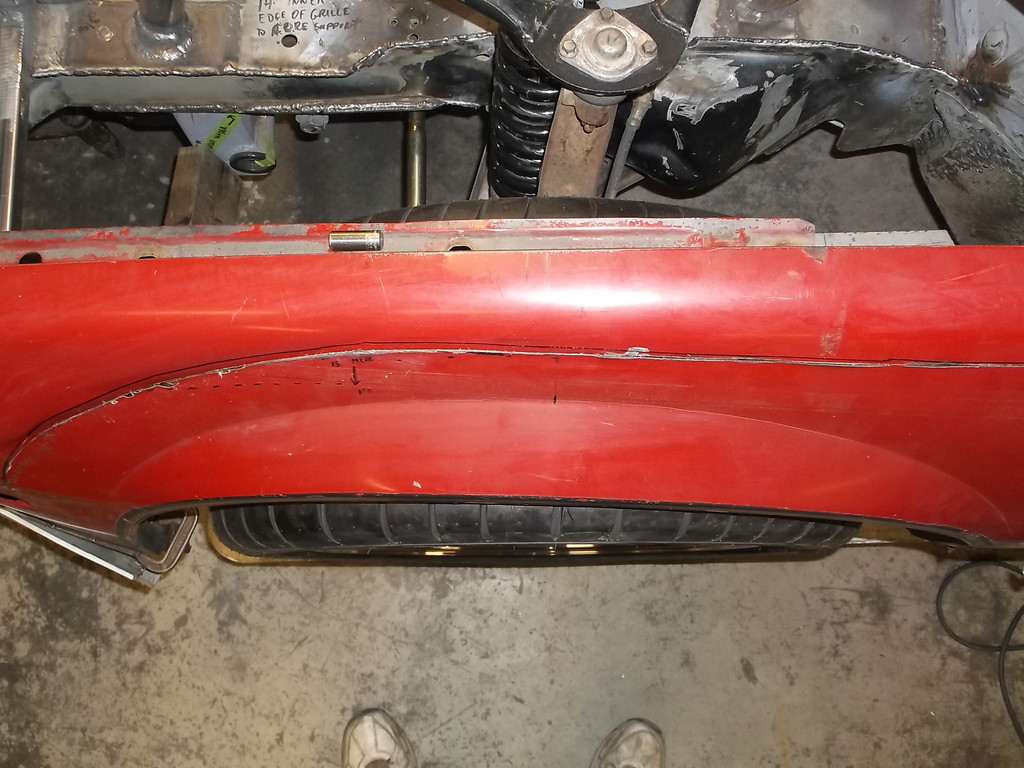
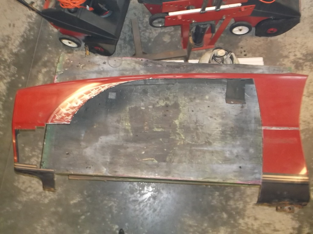
I decided to cut the factory flare out but leave it attached to the fender at the belt line. Pulling it out about a 1/2" put the edge even with the tire.
I will make a filler panel that will mimic the shape of the stock flare. Poster board template is a little rough but you get the idea.
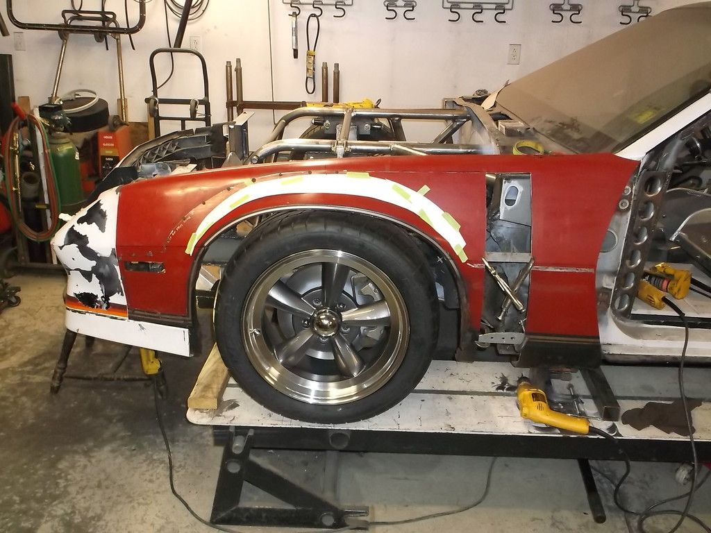

There is room to use a wheel with less back space and move the wheel inward 1 1/2" but I was wanting to run 18 x 10.5 wheels with a 315/30R18 track tire at all 4 corners. That would put the outside of the tire in the same location as now so I have to move the fender out either way. I wanted to keep fender as stock looking as possible and not add some type of generic flare. I decided to see how far out I could push the wheel opening.
By cutting the inside of the wheel lip at the belt line and also at the front of the fender I could get the lower half of the fender out quite a ways.

Looking down from the front

With a little effort I was able to pull the top out as well but still needed more.

I decided to cut the factory flare out but leave it attached to the fender at the belt line. Pulling it out about a 1/2" put the edge even with the tire.

I will make a filler panel that will mimic the shape of the stock flare. Poster board template is a little rough but you get the idea.


Thread Starter
Senior Member
Joined: Aug 2007
Posts: 682
Likes: 45
Re: Home brew road racer
Z28, thanks for following along. The car weighed 3200 before I started this project, 1900 front 1300 rear. A true 60/40 split. I am hoping to keep it there or a little less. I am also looking for a weight transfer of at least 5 percent.
As for the added steel most of what was added is behind the firewall and under the floor. I am more concerned about where the weight is rather tan the total weight of the car. I really think that the spartan interior and the lighter suspension and steering parts will offset most of the extra weight of the cage.
Once I get the front fenders done I can put it back on the scales and see where it stands.
Joined: Jun 2000
Posts: 5,364
Likes: 51
From: Enschede, Netherlands
Car: 82 TA 87 IZ L98 88 IZ LB9 88 IZ L98
Engine: 5.7TBI 5,7TPI 5.0TPI, 5,7TPI
Transmission: T5, 700R4, T5, 700R4
Axle/Gears: 3.08, 3.27, 3.45, 3.27
Re: Home brew road racer
Before final welding that fender, make sure you can turn the wheels full turn, I'm running into the same problem and need to possibly cut the fender back or move the lower portions out also in order to not interfere with the sheet metal.
Thread Starter
Senior Member
Joined: Aug 2007
Posts: 682
Likes: 45
Re: Home brew road racer
You can push the bottom out pretty far to where the front edge of the fender is even with the outer edge of the tire but it does put a little pucker in the gfx, not an actual kink or crease but a slight distortion that returns to original shape if the extended strut is taken out. To eliminate the pucker you have to make a small cut in the very front edge of the fender and rubber nose just above the where the "L" bracket connects the fender to the core support. This lets the bottom half of the fender flex and flare out with the gfx.
Here is a picture of my son's 84 Berlinetta with a Xenon gfx kit and 15 x 8 wheels w/ 4" bs and 275/60R15 TA's, a wide and fairly tall tire. This combo would not clear the lower lip so we made a longer strut bar from some aluminum tube and 1/4" heim joints. I did not cut the fender as described above and you can see the pucker where the front valance bolts to the fender.


Thread Starter
Senior Member
Joined: Aug 2007
Posts: 682
Likes: 45
Re: Home brew road racer
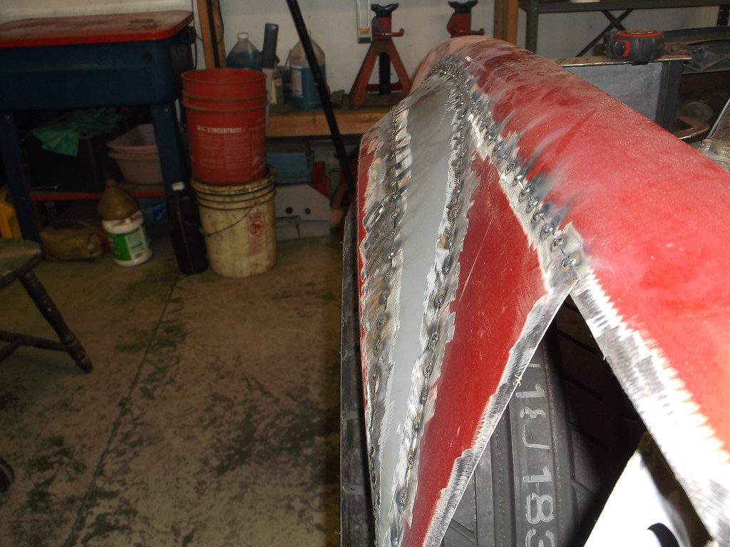
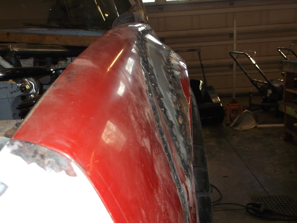
So on with the fender flairs. My thin sheet metal skills are lacking as evidenced by the poor outcome from filling in the sunroof hole in the roof. I tried to take some of the pointers offered in some of the post and hoped for a better out come. Lets just say I still need practice.
Satisfied with the fender sectioning I tacked the two pieces back together and set about extending the flair to cover the tire. I pulled the bottom of the fender opening out as much as the rubber nose and upper fender would allow, and made temporary struts to hold it there. I needed a fixed dimension for pulling out the flair so I could keep pass and driver side looking the same. I spaced the flare away from the main fender using a piece of 1 1/4 thick scrap would. This put the outer edge of the flair even with the outer edge of the tire. I used a small piece of scrap steel to hold the flair in position.
I left the fender as pictured, leaving a lot of extra metal to back up the patch. Hopefully it will help with warping and burn through.
Using the posterboard template I cut out a patch panel from the same 22ga sheet steel that the dash was made from. Once I was satisfied with the positioning I tacked it in place, starting in the center at the top edge and working to the outside. Again at this point it looks pretty good, blends the pulled out flair and oe fender together nicely. I am pretty full of myself at this point
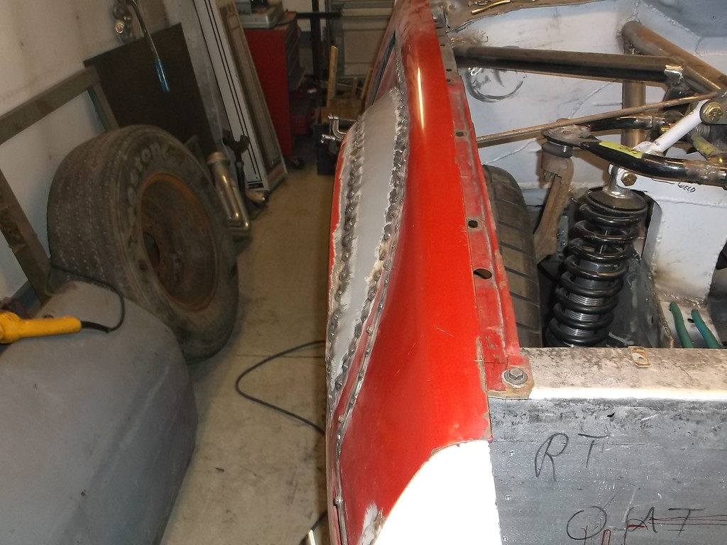
Satisfied with the fender sectioning I tacked the two pieces back together and set about extending the flair to cover the tire. I pulled the bottom of the fender opening out as much as the rubber nose and upper fender would allow, and made temporary struts to hold it there. I needed a fixed dimension for pulling out the flair so I could keep pass and driver side looking the same. I spaced the flare away from the main fender using a piece of 1 1/4 thick scrap would. This put the outer edge of the flair even with the outer edge of the tire. I used a small piece of scrap steel to hold the flair in position.

I left the fender as pictured, leaving a lot of extra metal to back up the patch. Hopefully it will help with warping and burn through.
Using the posterboard template I cut out a patch panel from the same 22ga sheet steel that the dash was made from. Once I was satisfied with the positioning I tacked it in place, starting in the center at the top edge and working to the outside. Again at this point it looks pretty good, blends the pulled out flair and oe fender together nicely. I am pretty full of myself at this point


Thread Starter
Senior Member
Joined: Aug 2007
Posts: 682
Likes: 45
Re: Home brew road racer
While I have the fenders and nose back on the car I thought it would be a good time to fit up an electric cooling fan. After a lot of research and given the space I have to work with I decided on the 2 speed ford fans from either a 94-97 Taurus w/ 3.8 v6 or the MarkVII/T bird fan and the Volvo 2 speed controller. Taking advantage of the unseasonably warm weather I visited the local pull-a-part as they listed at least one of each vehicle in inventory.
I was able to score the fan controller from a 1999 V70 volvo wagon but no radiators. Since the weather was great I just walked the rows looking for V8/V6 RWD vehicles. What I found was that 98 and newer Grand Marquis have an electric fan as the primary /only cooling fan. I never gave these a thought as I own a 97 Gran Marquis and the primary fan is engine driven with a HUGE electric fan for A/C and high temps.
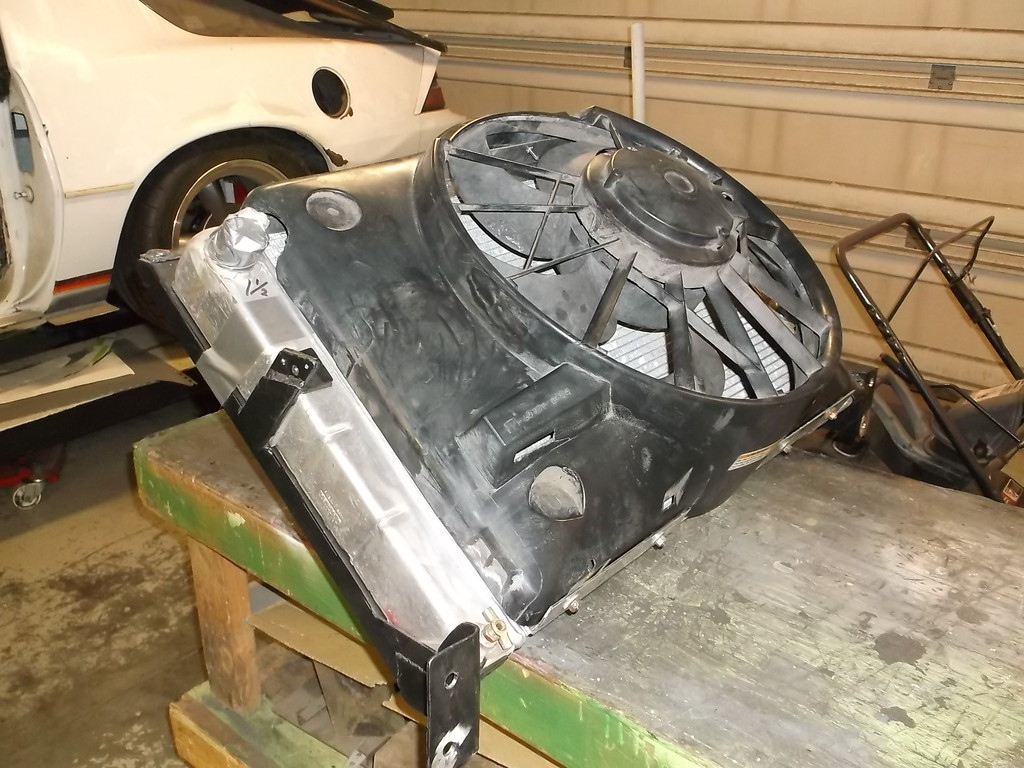
Here is the 2 speed fan unit I pulled from a 99 Gran Marquis.
engine side
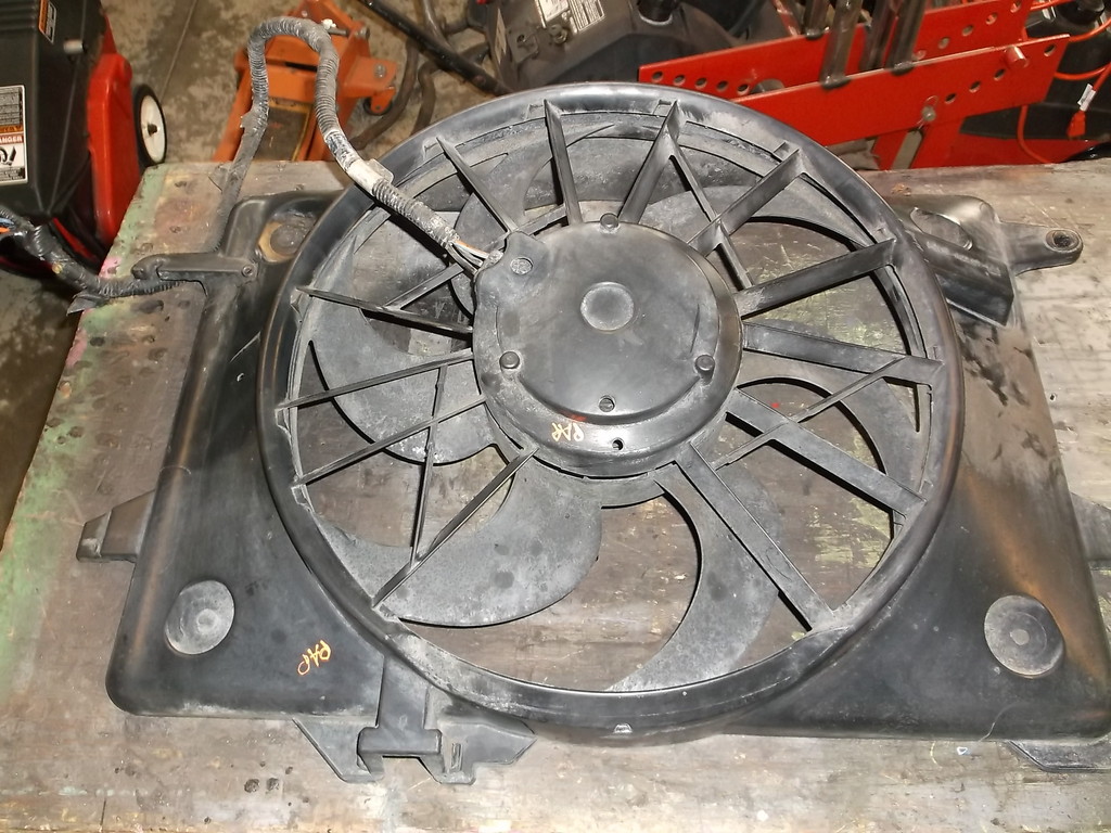
radiator side
side view, total depth is about 9" from surface of radiator core.
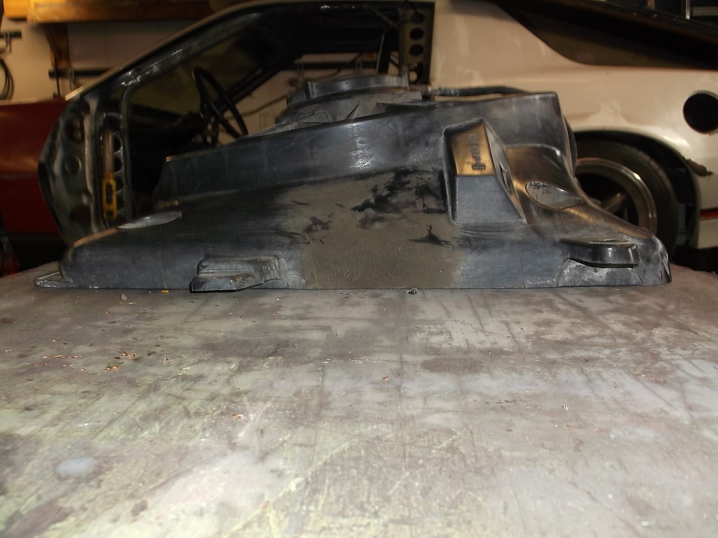
The shroud measures 26 3/4w x 19h x 9d, not counting the factory mounting ears (I cut those off). The actual fan is 16" diameter and the motor is very big, much larger than all the aftermarket fans. Three wire motor, black is ground, blue is low speed and orange is high speed. This seems to be the same motor as in the Tbirds and Mark's just made onto a different shroud.
Here is the Volvo 2 speed fan controller.
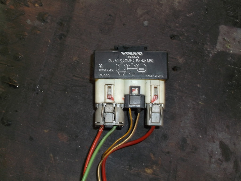
Single red wire on right is power in. 2 wire plug in middle is for input from temp sensors. Large 2 wire plug on left is power out to fan, green wire is low speed and red wire is high speed. I laid fan and controller out on the work bench and wired the power wire from controller to a lawn mower battery positive post and the ground wire from the fan to the negative post. Connected the hi/low wires from fan to hi/low wires from the controller. By grounding the individual temp sensor wires from the middle plug on the controller you activate hi or low speeds on the fan. This controller disconnects power to low speed windings any time hi speed is activated.
Low speed is whisper quiet and does not seem to pull a lot of amps at start up. High speed comes on nice and easy since the motor is already spinning, so no big power spike to hurt the alternator or other electronics. High speed blows air like an F4 tornado!
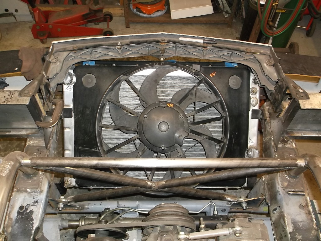
Here are pics of fan positioned in car for test fit. I put it in upside down to help direct the air up toward the hood.
It really fills up the space!!!!
The radiator core is about 25 3/4 across, so the fans rest on the tanks just past the weld seam. The fan is also an inch taller than the core. Mounting plans call for simple aluminum angle riveted to inside of shroud, top and bottom, and those will be bolted to the channels at top and bottom of radiator. I will space the shroud up off the tanks so there is no chance of the shroud rubbing a hole in the aluminum, and seal the sides with foam tape.
I was able to score the fan controller from a 1999 V70 volvo wagon but no radiators. Since the weather was great I just walked the rows looking for V8/V6 RWD vehicles. What I found was that 98 and newer Grand Marquis have an electric fan as the primary /only cooling fan. I never gave these a thought as I own a 97 Gran Marquis and the primary fan is engine driven with a HUGE electric fan for A/C and high temps.
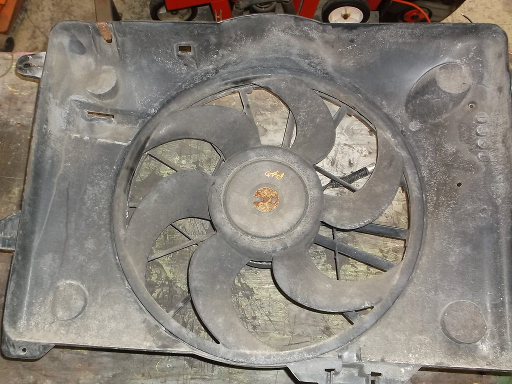
Here is the 2 speed fan unit I pulled from a 99 Gran Marquis.
engine side

radiator side

side view, total depth is about 9" from surface of radiator core.

The shroud measures 26 3/4w x 19h x 9d, not counting the factory mounting ears (I cut those off). The actual fan is 16" diameter and the motor is very big, much larger than all the aftermarket fans. Three wire motor, black is ground, blue is low speed and orange is high speed. This seems to be the same motor as in the Tbirds and Mark's just made onto a different shroud.
Here is the Volvo 2 speed fan controller.

Single red wire on right is power in. 2 wire plug in middle is for input from temp sensors. Large 2 wire plug on left is power out to fan, green wire is low speed and red wire is high speed. I laid fan and controller out on the work bench and wired the power wire from controller to a lawn mower battery positive post and the ground wire from the fan to the negative post. Connected the hi/low wires from fan to hi/low wires from the controller. By grounding the individual temp sensor wires from the middle plug on the controller you activate hi or low speeds on the fan. This controller disconnects power to low speed windings any time hi speed is activated.
Low speed is whisper quiet and does not seem to pull a lot of amps at start up. High speed comes on nice and easy since the motor is already spinning, so no big power spike to hurt the alternator or other electronics. High speed blows air like an F4 tornado!
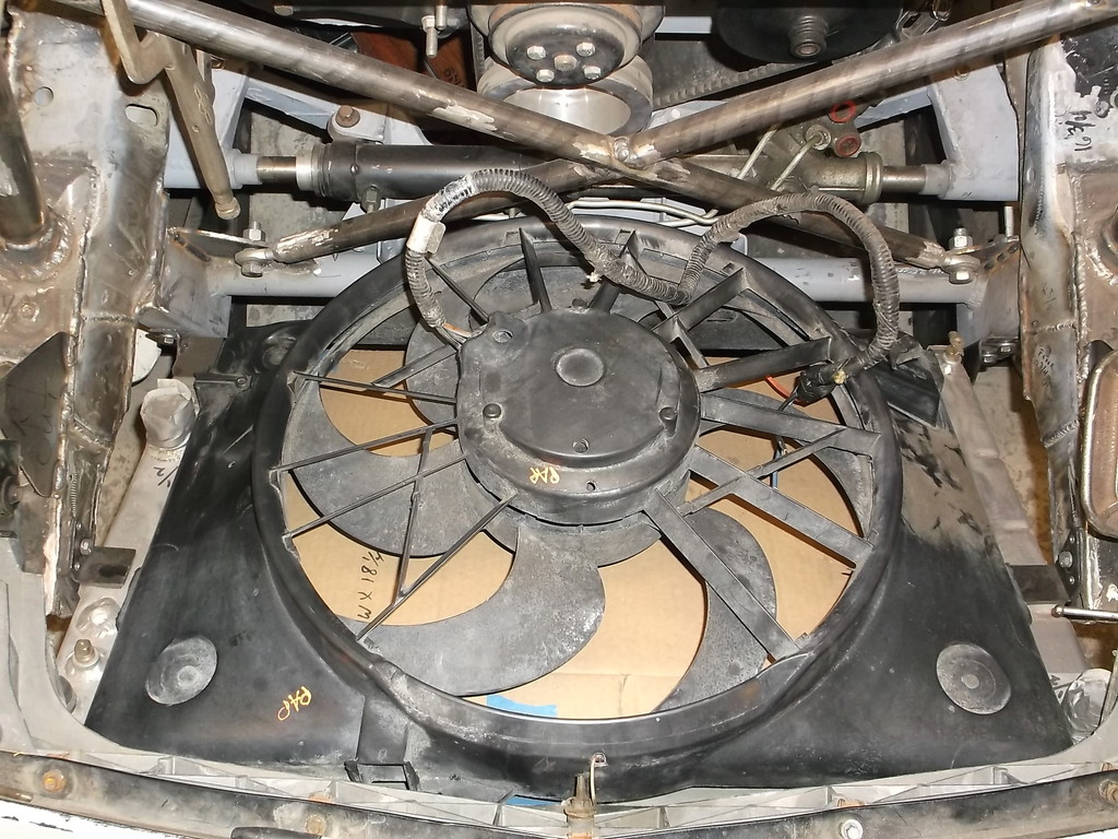
Here are pics of fan positioned in car for test fit. I put it in upside down to help direct the air up toward the hood.
It really fills up the space!!!!


The radiator core is about 25 3/4 across, so the fans rest on the tanks just past the weld seam. The fan is also an inch taller than the core. Mounting plans call for simple aluminum angle riveted to inside of shroud, top and bottom, and those will be bolted to the channels at top and bottom of radiator. I will space the shroud up off the tanks so there is no chance of the shroud rubbing a hole in the aluminum, and seal the sides with foam tape.
Thread Starter
Senior Member
Joined: Aug 2007
Posts: 682
Likes: 45
Re: Home brew road racer
i was so excited about this fan setup that I stopped working on the fenders and dropped out the radiator to make a mount for the fan. Brackets were cut from 1/16 sheet aluminum and bent on my homemade brake. The 4 alignment dowles on the bottom were scavenged from the bottoms of my APV van headlights. Top of shroud is bolted down with discarded fender bolts.
Besides cutting off all of the OE mounting ears I also had to notch the shroud for hose clearance.
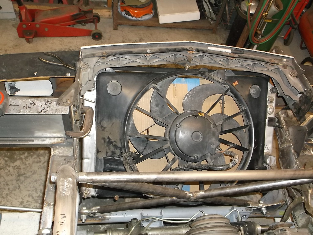
Here is complete unit as it will sit in the car.
And back in the car.
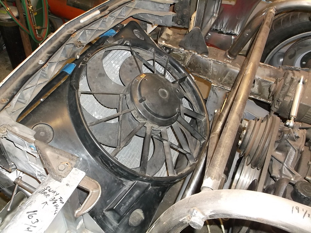
I couldn't be happier with the way this turned out. The shroud covers the entire core and the 2 speed fan is both quiet and powerful. The Volvo controller is super slick and both pieces offer OEM reliability. All this for only $47.00.


Besides cutting off all of the OE mounting ears I also had to notch the shroud for hose clearance.


Here is complete unit as it will sit in the car.

And back in the car.


I couldn't be happier with the way this turned out. The shroud covers the entire core and the 2 speed fan is both quiet and powerful. The Volvo controller is super slick and both pieces offer OEM reliability. All this for only $47.00.
Thread Starter
Senior Member
Joined: Aug 2007
Posts: 682
Likes: 45
Re: Home brew road racer
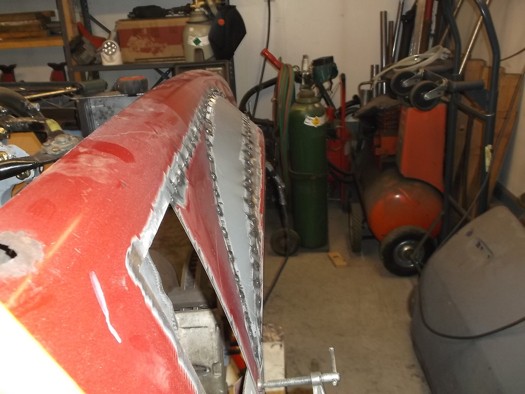
So back to piecing the left front fender back together. I decided to just tack eveything in place and finish them up later with the rest of the body work.
And a comparison of left and right frontal view. Hopefully the two sides will look very similar.
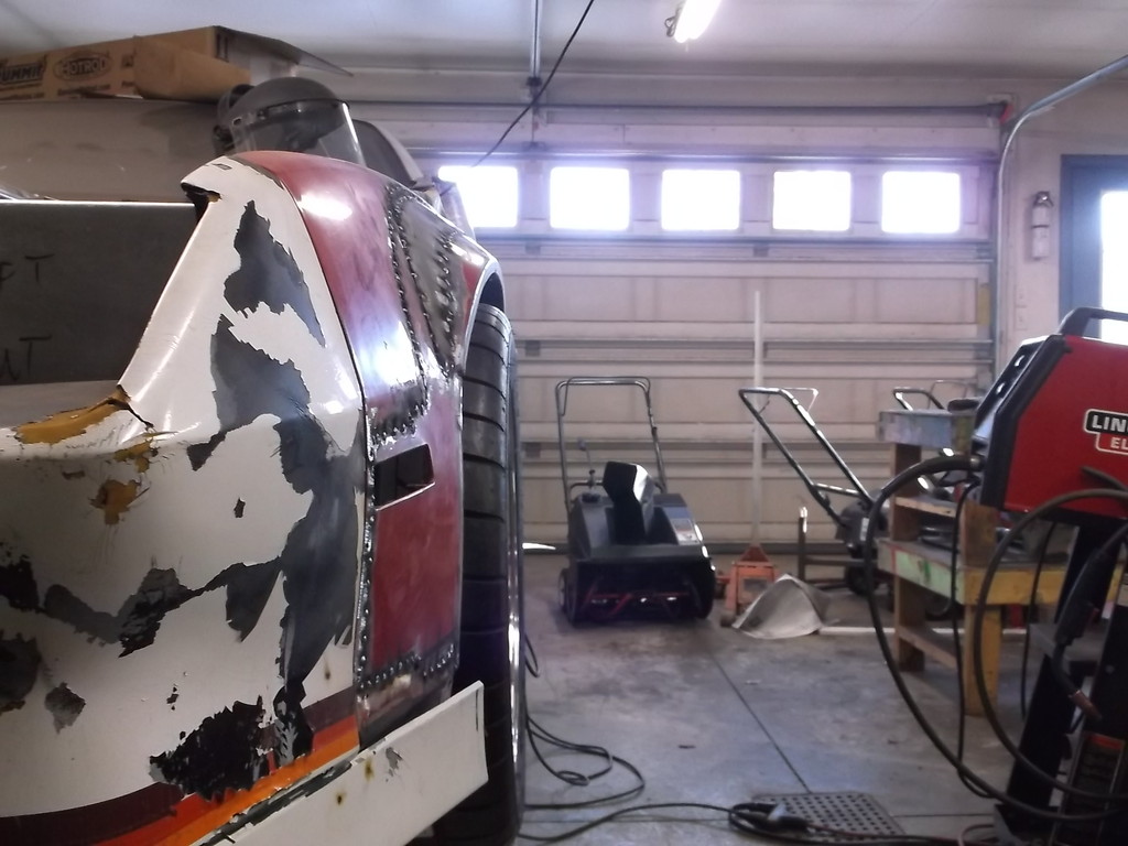


And a comparison of left and right frontal view. Hopefully the two sides will look very similar.


Thread Starter
Senior Member
Joined: Aug 2007
Posts: 682
Likes: 45
Re: Home brew road racer
Lord I hope it turns out that way.
I want to thank everybody that has looked in on my insanity and/or made comments and suggestions pro or con. The comments keep me motivated to keep plugging away after 5 long years.
I made mention in a post back in August that I had to quit working due to a medical condition. I won't go into a lot of detail but to say I developed a severe headache disorder called hemi cranial continuum. Between the headaches and the drugs I feel stoned and confused most days. If I type something here that doesn't sound right or I show a picture of something that doesn't seem right or safe PLEASE SPEAK UP!!!! I triple check my work now and try to catch my mistakes as I make them but I am sure I have and will miss somethings.
Thread Starter
Senior Member
Joined: Aug 2007
Posts: 682
Likes: 45
Re: Home brew road racer
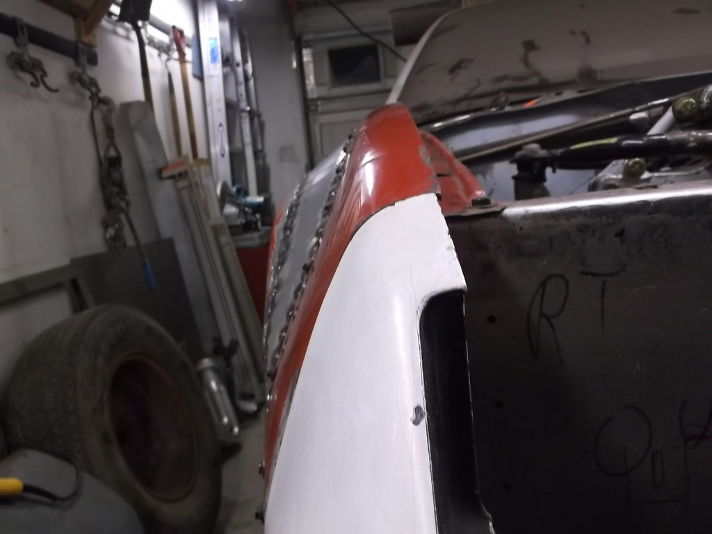
OK so back to work. When building the flares I could never get the left flare to cover the outer edge of the tire completely (off 3/8 to 1/2) while the right hung over the outside. Given that I built the front end from scratch I was doubting myself that I had plotted the vehicle center line off center or that the frame rails were still tweeked from the accident. I had checked and rechecked both of these issues multiple times before, during and after the suspension build. The more I looked the more I realized that the suspension wasn't offset, the front of the fenders were.
The last time I had the hood on I noticed that the gaps between hood and fenders were skewed diagonally. The front of the fenders were positioned off of the OE core support so I thought that was good. I guess there was still some misalignment from the accident. I removed the bolts from the front of the fenders and loosened the rears and just shoved the nose to the left. Wallah, both the fenders and hood align now and the flares cover both wheels. Yeah!
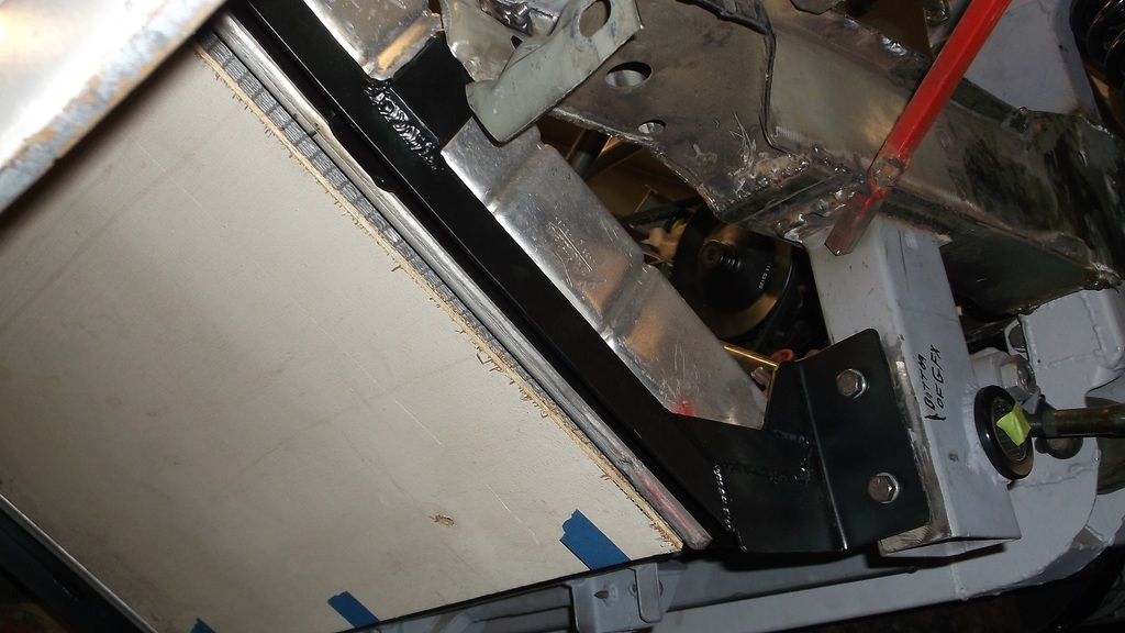
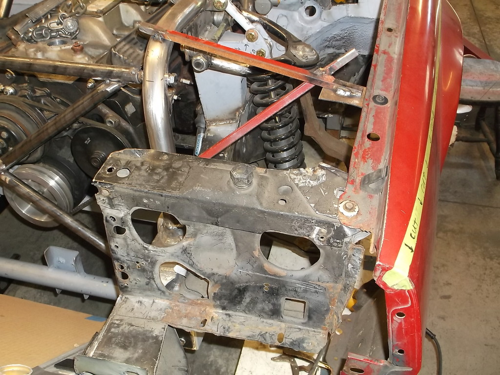
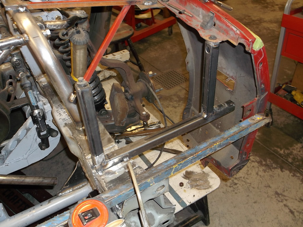
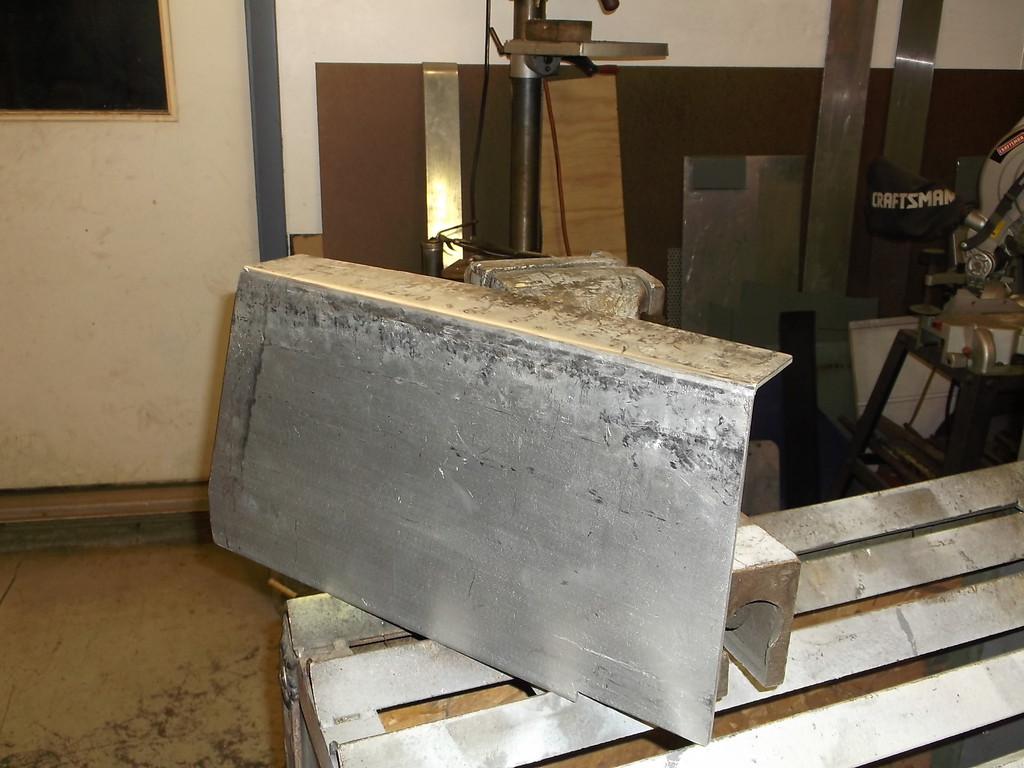
I needed to make a support to reattach the center fiberglass support for the nose to my fabbed fender/headlight support brackets. Thought I could kill 2 birds at once and close off the sides around the cooling fan outlet. Since the nose is fairly heavy I needed something more than thin aluminum. Solution, STOP SIGN. The pattern for this piece was a little complex, took a few sketches and paper cutouts to get right.
Discarded rural stop sign and pattern.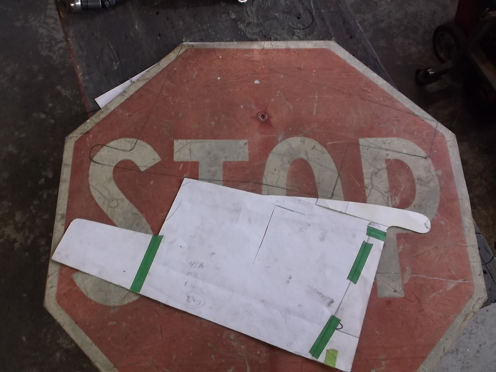
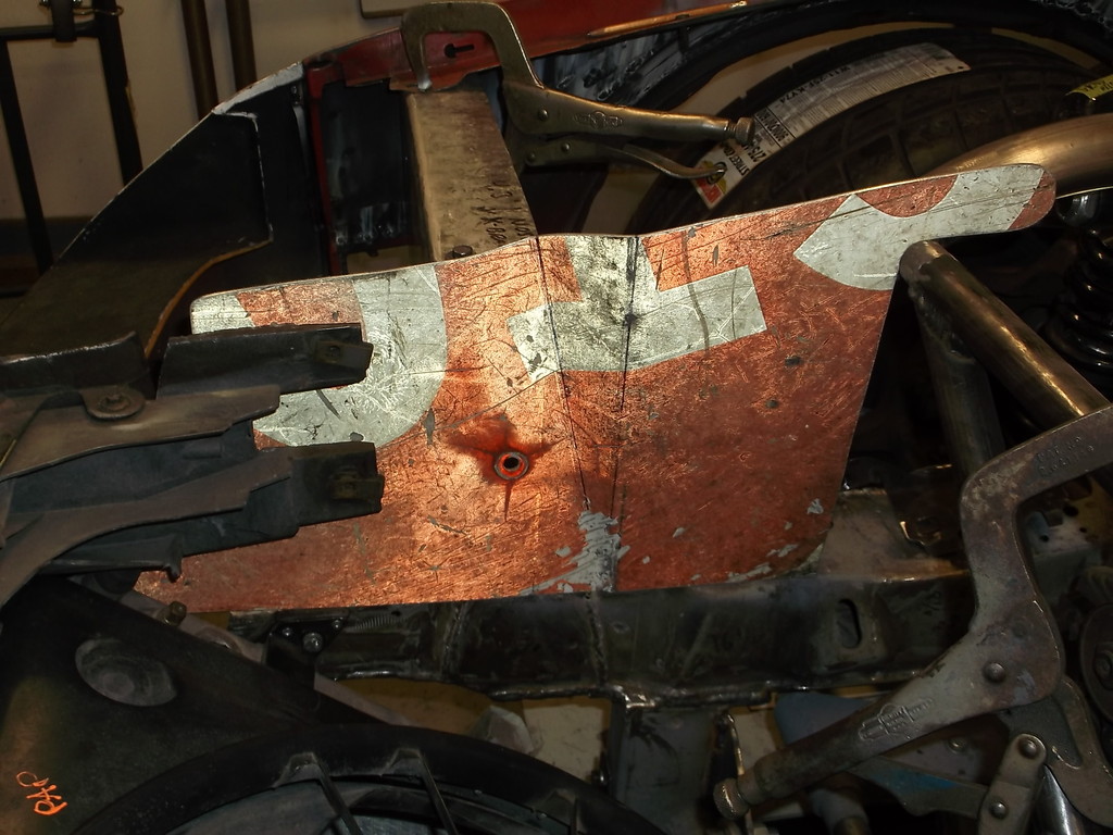
The fiberglass support was busted when the car was wrecked so I cut away all but the center piece with the adjustment flanges. My pattern had to be trimmed to around the stiffening ribs on the flanges.
I am not sure how I decided that the brace needed to be bent like this but it worked well.
Because my fender braces were welded in before I shifted the fron fenders to the left I ended up with a 3/4" gap that I had to address.
I ended up making an added offset boxed mount to bridge the gap. Boxed mount is at top of picture.
secured rear of shield with a couple weld tabs.
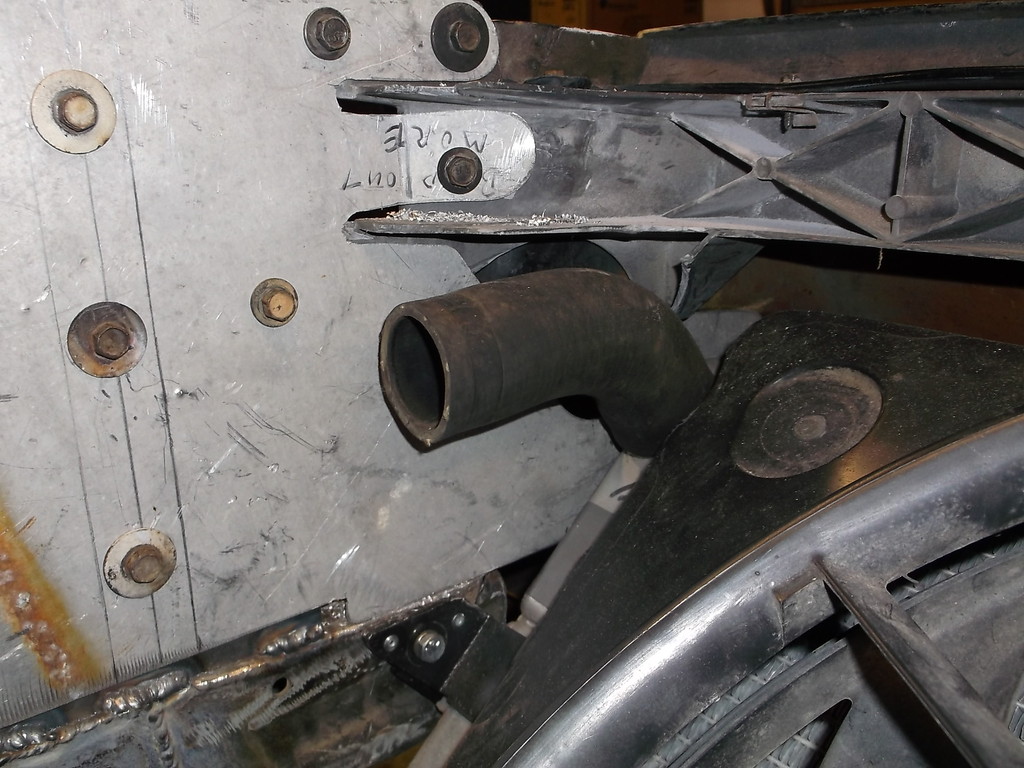
Left side lined right up but had its own issues as it had to clear the upper hose on radiator.
The last time I had the hood on I noticed that the gaps between hood and fenders were skewed diagonally. The front of the fenders were positioned off of the OE core support so I thought that was good. I guess there was still some misalignment from the accident. I removed the bolts from the front of the fenders and loosened the rears and just shoved the nose to the left. Wallah, both the fenders and hood align now and the flares cover both wheels. Yeah!
I needed to make a support to reattach the center fiberglass support for the nose to my fabbed fender/headlight support brackets. Thought I could kill 2 birds at once and close off the sides around the cooling fan outlet. Since the nose is fairly heavy I needed something more than thin aluminum. Solution, STOP SIGN. The pattern for this piece was a little complex, took a few sketches and paper cutouts to get right.
Discarded rural stop sign and pattern.

The fiberglass support was busted when the car was wrecked so I cut away all but the center piece with the adjustment flanges. My pattern had to be trimmed to around the stiffening ribs on the flanges.

I am not sure how I decided that the brace needed to be bent like this but it worked well.

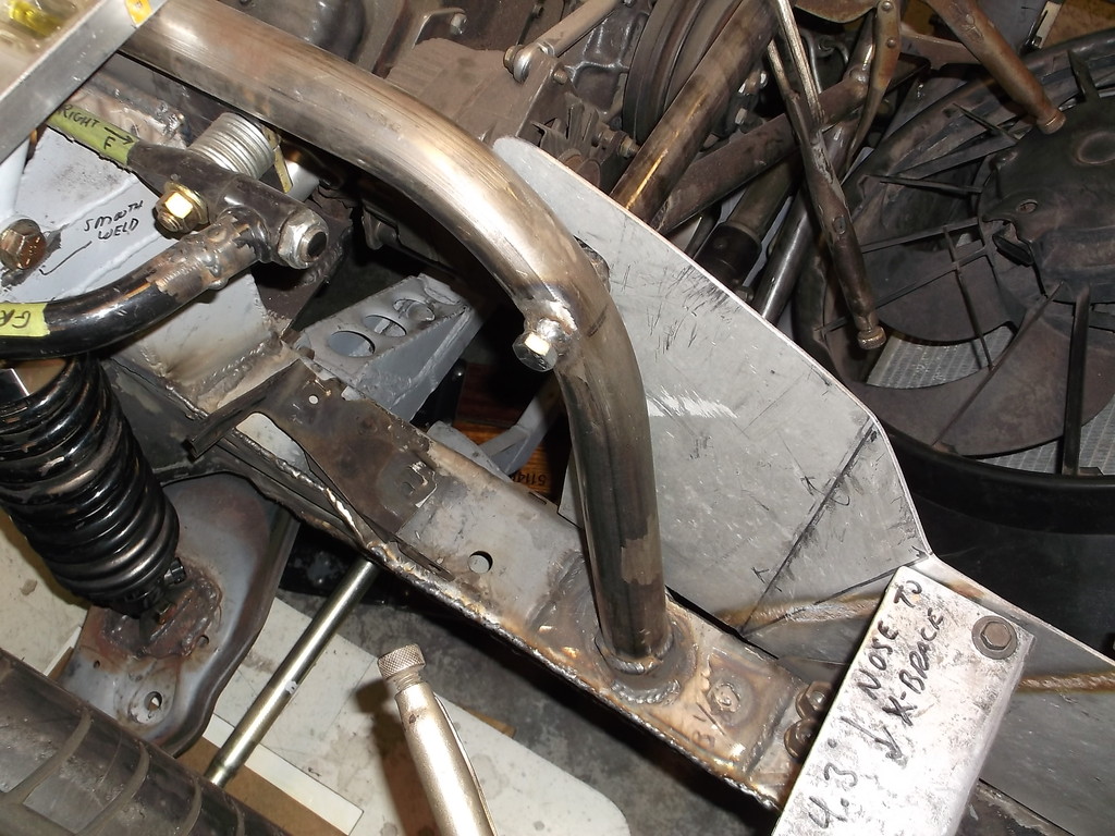
Because my fender braces were welded in before I shifted the fron fenders to the left I ended up with a 3/4" gap that I had to address.

I ended up making an added offset boxed mount to bridge the gap. Boxed mount is at top of picture.

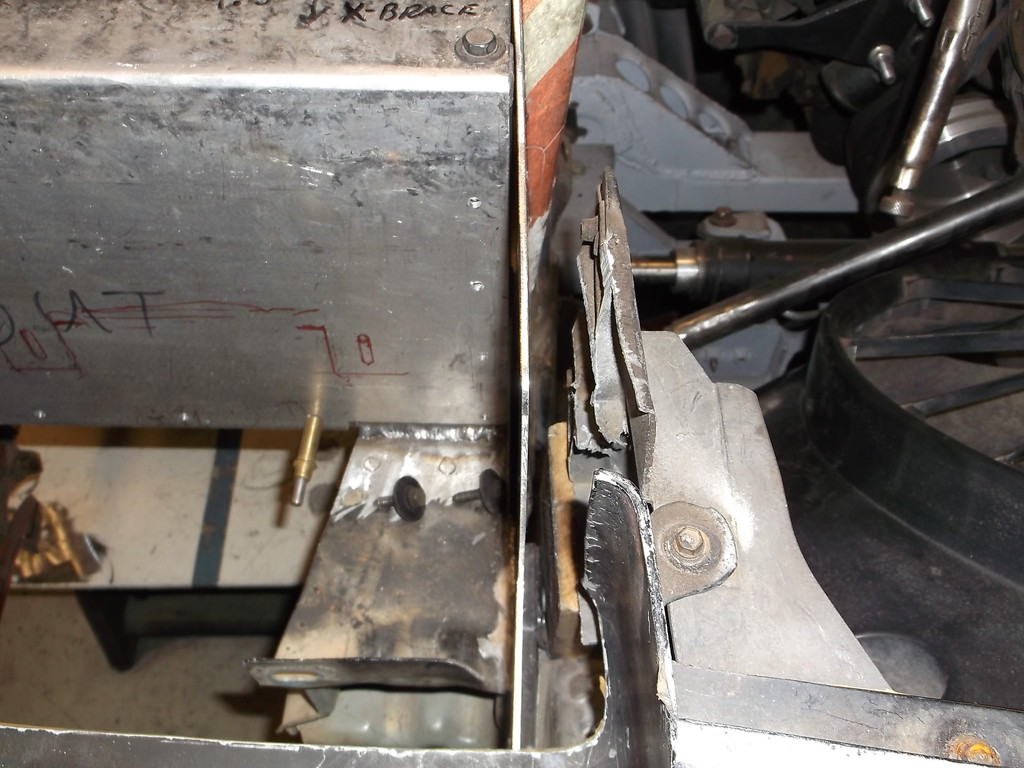
secured rear of shield with a couple weld tabs.

Left side lined right up but had its own issues as it had to clear the upper hose on radiator.

Thread Starter
Senior Member
Joined: Aug 2007
Posts: 682
Likes: 45
Re: Home brew road racer
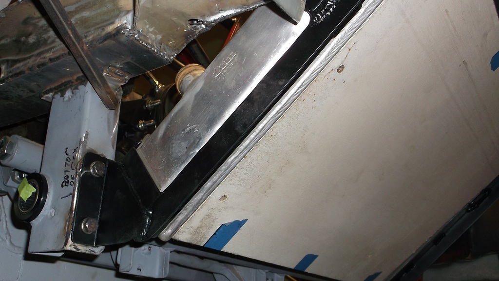
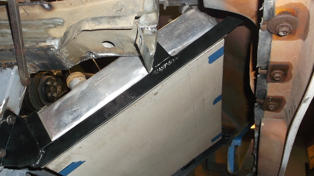
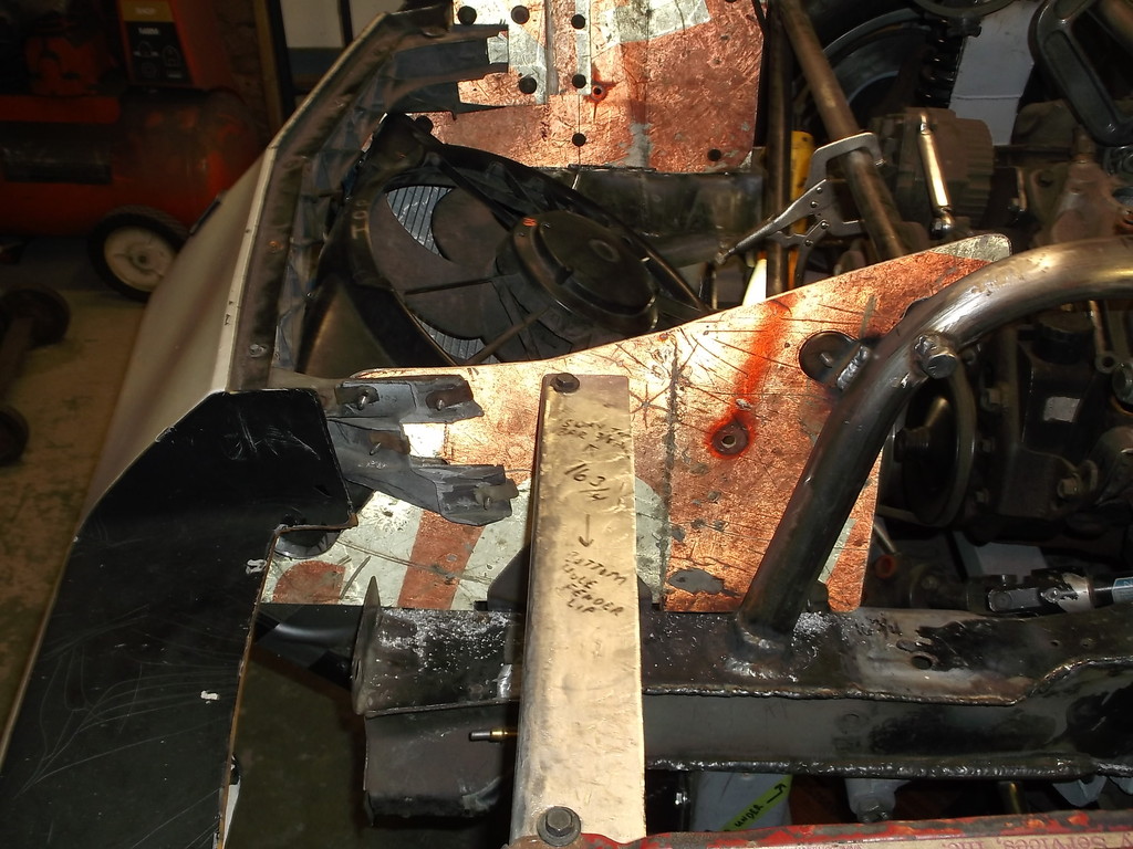
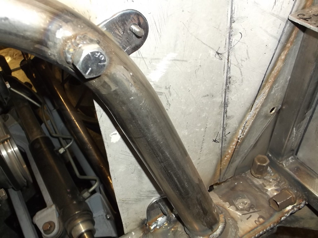
I mocked up the radiator hose layout using sections of old radiator hoses to get the 90 and 45 degree angles I needed and coupled them together with short pieces of rollbar tubing.
Lower hose was pretty simple.
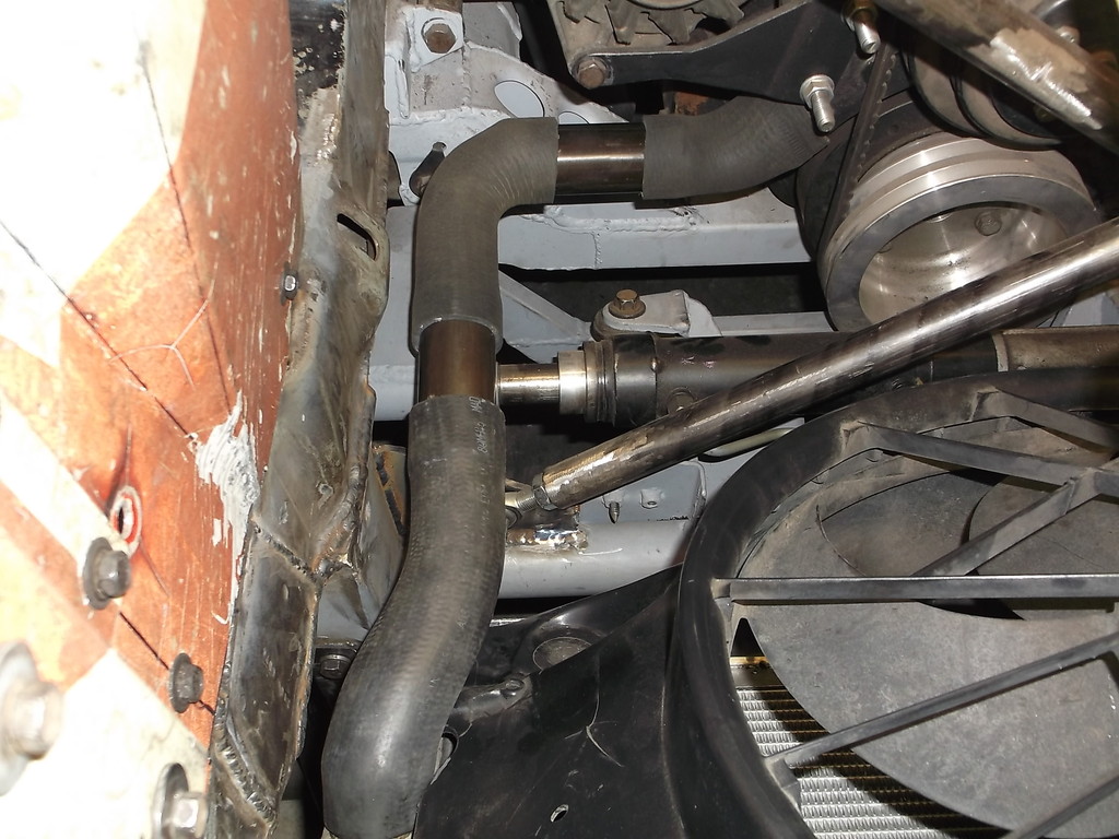
Upper hose is much longer and has to rise almost 12" from radiator to thermostat housing. The long piece of tubing at top will be replaced by an inline remote fill pipe with a radiator neck and pressure cap.
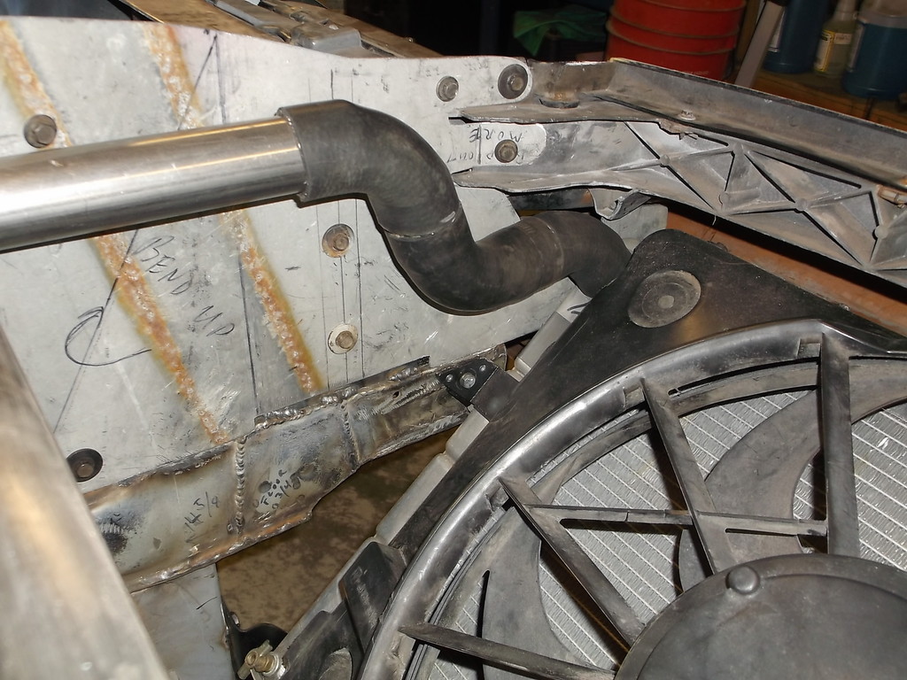
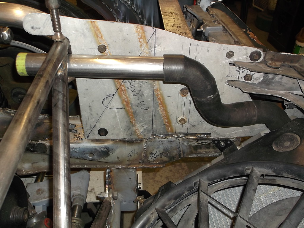
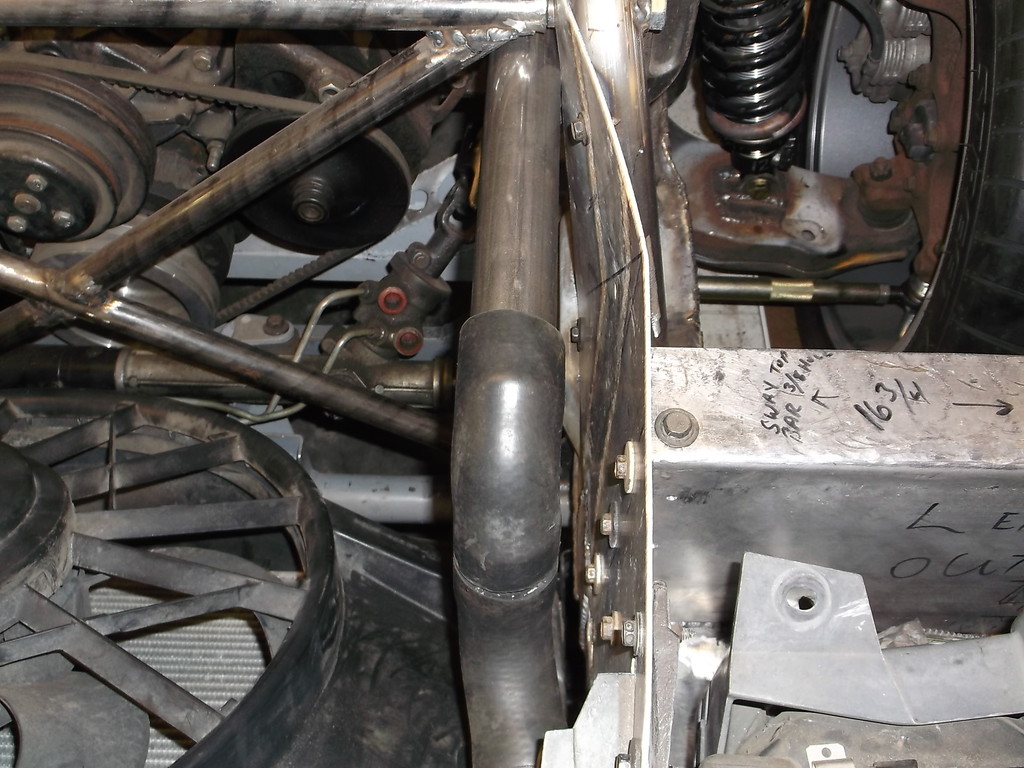
To minimize the number of hose clamps and potential leaks I will be replacing the "S" bend in the upper hose with one fabbed from a 1 1/2" stainless header tubing U-bend. I am hoping to have enough straight tubing left over to use on the lower hose. If not i will probably just get a prebent 90 degree bend and eliminate the rubber 90 from the lower hose.
Lower hose was pretty simple.

Upper hose is much longer and has to rise almost 12" from radiator to thermostat housing. The long piece of tubing at top will be replaced by an inline remote fill pipe with a radiator neck and pressure cap.


To minimize the number of hose clamps and potential leaks I will be replacing the "S" bend in the upper hose with one fabbed from a 1 1/2" stainless header tubing U-bend. I am hoping to have enough straight tubing left over to use on the lower hose. If not i will probably just get a prebent 90 degree bend and eliminate the rubber 90 from the lower hose.