
Home brew road racer


Thread Starter
Senior Member

Joined: Aug 2007
Posts: 682
Likes: 45
Re: Home brew road racer
Flash, thanks for all the tips. I think I hit most of your points in my attempt. In hind sight I probably should have tacked the panel in enough to hold it in place, removed my butt weld claps and made up some braces to support it from underneath and then finish welding it in. Now I will have to do it after the fact. Oh well, live and learn. And this project has been one big learning experience.
Thread Starter
Senior Member
Joined: Aug 2007
Posts: 682
Likes: 45
Re: Home brew road racer
Now on to the front suspension. My plan is to retro fit the spindles, brakes, upper an lower control arms, sway bar, and the rack and pinion from an LS Camaro to the stock third gen frame rails. I have taken a lot of measurements and I am about 90% sure I can pull this off. I have only seen this attempted a couple times on TGO with one member splicing the entire front clip from a 4th gen to the 3rd gen. I am hoping to keep it as simple as I can.
We modify the front of these cars to correct some of GM short comings, like tiny brakes, very nose heavy weight distribution, low torsional stiffness, poor camber gain, and tire and wheel size restrictions. We spend many hundreds of dollars on tubular k members and control arms and coil overs to lose maybe 50lbs. We want the quick response and tight feel of rack and pinion but nothing matches the steering arm length. We'll spend big bucks on big brakes to slow down our big wheels that only fit with big spacers. And finally if we want the cars to run well in AX or on a road course we need to run as much negative camber as possible and limit body roll with stiff springs and big roll bars.
If I can pull this off, all the above problems will be greatly reduced or eliminated. Please feel free to offer comments and suggestions to help me make this work. Because I am not 100% sure this is doable I will be taking a cautious approach and won't be cutting the wheel wells out until I have a good K member in place to properly position the lower control arm and rack.
HERE WE GO!!!!!!!!!!!!!
Thread Starter
Senior Member
Joined: Aug 2007
Posts: 682
Likes: 45
Re: Home brew road racer
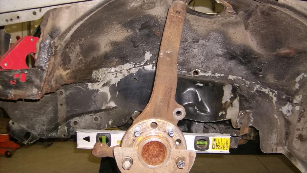
Before I stripped the front end I had to locate the spindle centerlines and mark them on the ramps. I also projected this mark to the frame structure above the wheel well using a 4ft level and double checking with the plumb.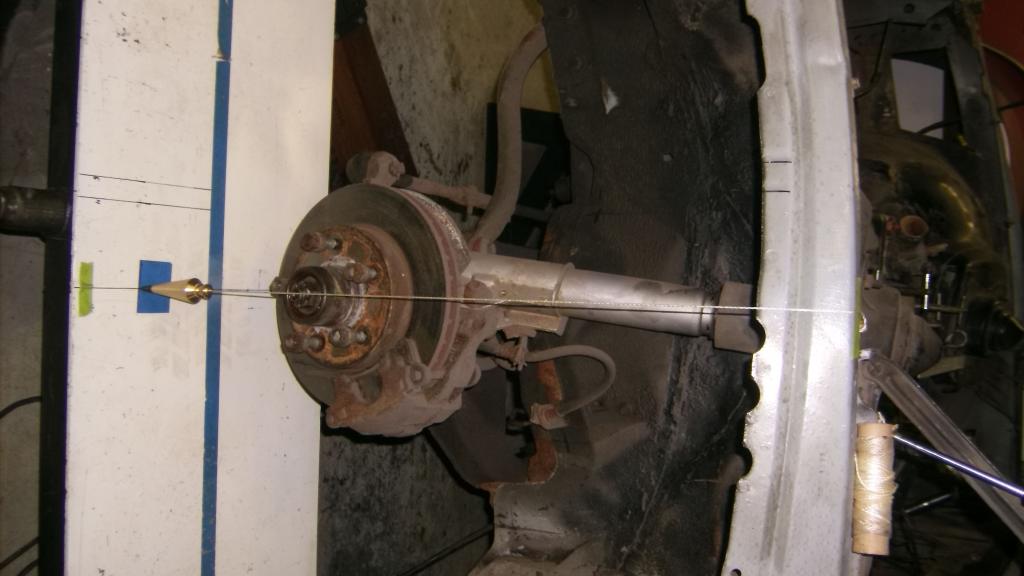
To make sure the centerlines were directly across from one another I scribed a line through the CL across the width of each ramp with a machinist square. Running a tight string across from ramp to ramp confirmed that the CL's were in line as the string followed the scribed lines perfectly.


To make sure the centerlines were directly across from one another I scribed a line through the CL across the width of each ramp with a machinist square. Running a tight string across from ramp to ramp confirmed that the CL's were in line as the string followed the scribed lines perfectly.

Last edited by 83RDRACR; Nov 29, 2014 at 07:00 PM. Reason: repost pictures
Thread Starter
Senior Member
Joined: Aug 2007
Posts: 682
Likes: 45
Re: Home brew road racer
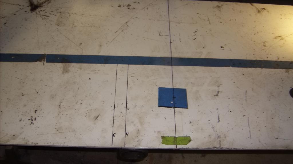
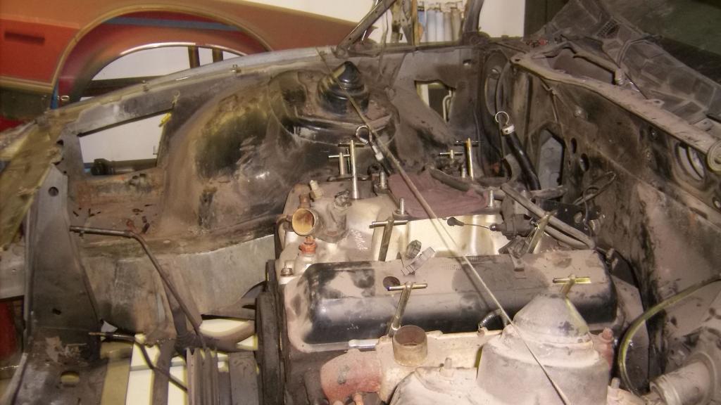
The next thing I had to do was find the centerline of the car front to rear. The CL of a car is determined by track width and not some point in the middle of the frame. If the wheel offsets are the same and the spindles are the same then we can use the grease fitting at the center of the lower ball joints as reliable measuring points as it would be the same distance from the center of the tread for both sides. My measurement was 57 1/4 so center was 28 5/8 inward from there.
As I was looking to find a place on the k member to mark the center I cleared away some grease and there was a hole in the k member at that exact spot. I take it that it must be an alignment hole for assembly purposes. I took two other measurements off of my sfc's and ran a string line from k member to the rear most cross member ahead of the rear axle. I did not take a measurement but it appears that the stock engine and trans are offset to the right about 1 1/2 inches.
I am going to drop a plumb down from the string line to my garage floor in several places and drill into the concrete so I will have a CL reference as I go on.
Thread Starter
Senior Member
Joined: Aug 2007
Posts: 682
Likes: 45
Re: Home brew road racer
With the CL's marked I stripped the front suspension and steering off. I am going to weigh all of it once I get the K member off and compare to the LS assembly shown in an earlier post.
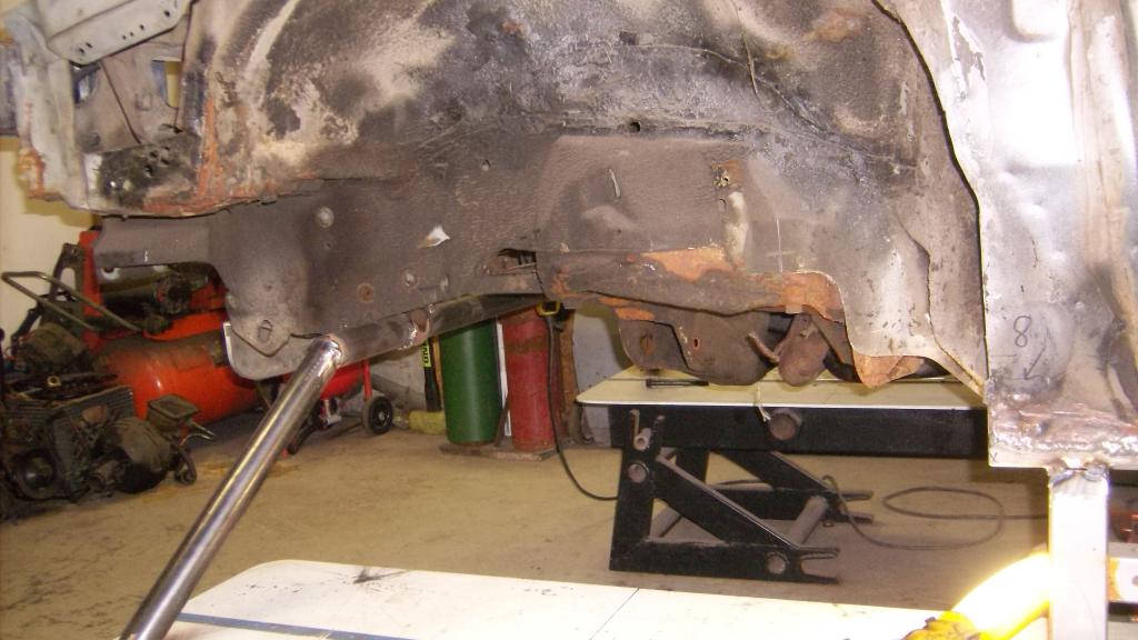
As I mentioned in my very fist post this car was wrecked, hit hard on the left front from about center of tire forward. It was hard enough that it bent both frame horns to the right and the right front fender had a slight buckle in it. I had it pulled back straight by a very reputable body shop and drove the car for several weeks before I started this project. It seemed to sit level, steer straight and handled ok. Even so I have worried about it being tweaked.
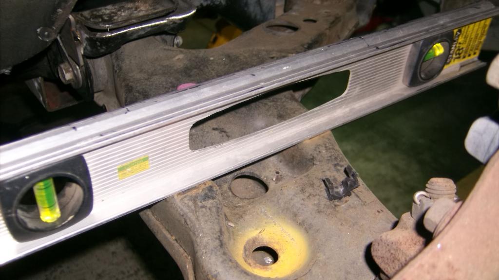
I had taken diagonal measurements across the top of the engine compartment as best I could and it appeared to be square to within a 1/8" no matter what I used for reference. I was also worried about any twist in the frame where one rail would be higher or lower than the other. With the rubber nose and the fenders off I was able to get some measurements that make me feel confident that its pretty straight. I placed my 4ft level across the front frame horns just behind the impact bar mount flanges and put my digital level on top of that. The bubble level looked nearly perfect and the digital level shows .6 of 1 degree inclination. I repositioned the levels several times and it did not vary by more than .1. I got similar results with a piece of 2x2 tubing running across the frame structure above the wheel wells in several different locations so I am going to move forward confident that the frame rails are at least as straight as GM made them.
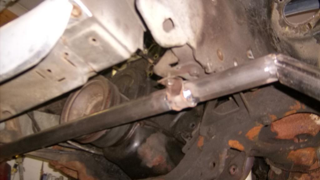
I was still worried that the frame might spring out of shape when I unbolt the K member. It looks good now and I want to keep it that way. Looking for a way to hold the rails in their current location with out getting in the way of setting up the new suspension I came up with this....
1 3/4 schedule 40 pipe welded to the old sway bar brackets with a down leg of 1 5/8 tubing welded to the front of the ramps
As I mentioned in my very fist post this car was wrecked, hit hard on the left front from about center of tire forward. It was hard enough that it bent both frame horns to the right and the right front fender had a slight buckle in it. I had it pulled back straight by a very reputable body shop and drove the car for several weeks before I started this project. It seemed to sit level, steer straight and handled ok. Even so I have worried about it being tweaked.
I had taken diagonal measurements across the top of the engine compartment as best I could and it appeared to be square to within a 1/8" no matter what I used for reference. I was also worried about any twist in the frame where one rail would be higher or lower than the other. With the rubber nose and the fenders off I was able to get some measurements that make me feel confident that its pretty straight. I placed my 4ft level across the front frame horns just behind the impact bar mount flanges and put my digital level on top of that. The bubble level looked nearly perfect and the digital level shows .6 of 1 degree inclination. I repositioned the levels several times and it did not vary by more than .1. I got similar results with a piece of 2x2 tubing running across the frame structure above the wheel wells in several different locations so I am going to move forward confident that the frame rails are at least as straight as GM made them.
I was still worried that the frame might spring out of shape when I unbolt the K member. It looks good now and I want to keep it that way. Looking for a way to hold the rails in their current location with out getting in the way of setting up the new suspension I came up with this....
1 3/4 schedule 40 pipe welded to the old sway bar brackets with a down leg of 1 5/8 tubing welded to the front of the ramps


Last edited by 83RDRACR; Nov 29, 2014 at 07:04 PM. Reason: repost pictures
Thread Starter
Senior Member
Joined: Aug 2007
Posts: 682
Likes: 45
Re: Home brew road racer
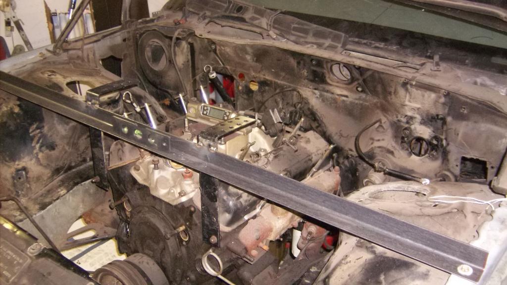
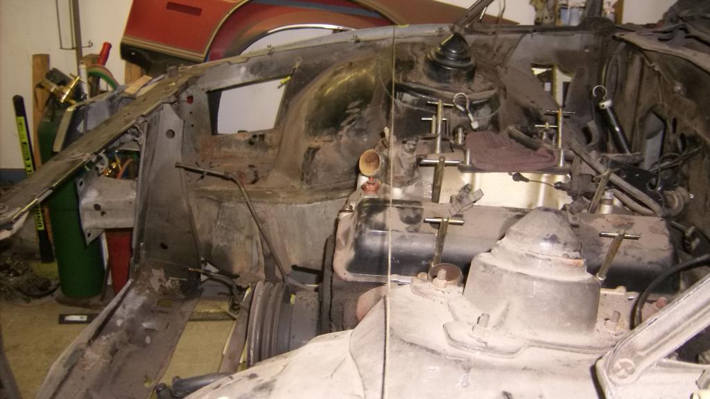
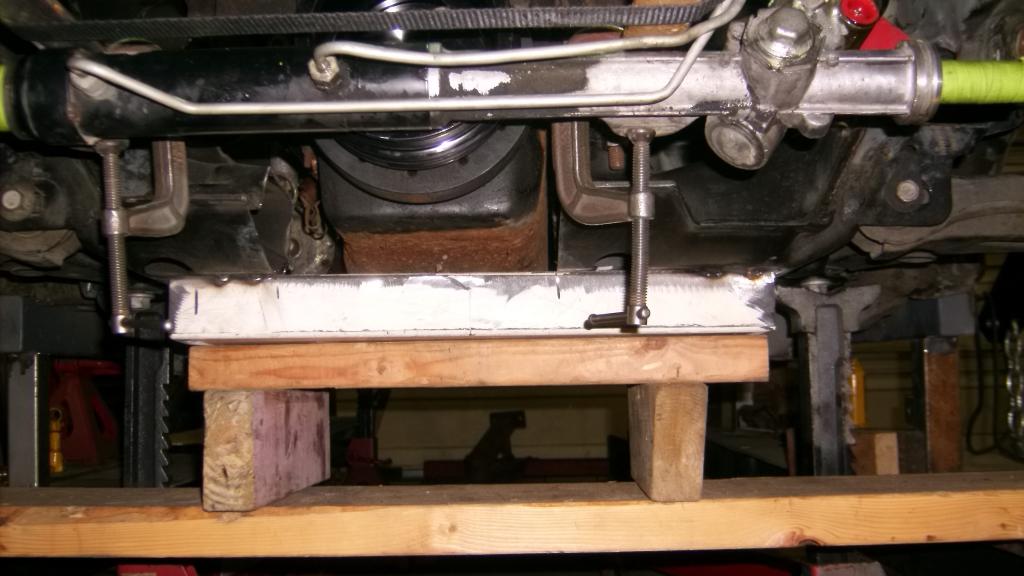
Besides locating the lower control arms and steering rack, the new k member has to clear the oil pan and headers, It also may provide the front engine mounts. So now I needed a simple structure to hold the engine in place when I take the K member out. In checking to make sure the engine was level I discovered that the right side engine mount had turned to mush from a prolonged oil leak and that the engine tilted down to the right about 3/4 ".

Last edited by 83RDRACR; Nov 29, 2014 at 07:09 PM. Reason: repost pics
Thread Starter
Senior Member
Joined: Aug 2007
Posts: 682
Likes: 45
Re: Home brew road racer
Here is where things take a turn from the norm. One of the main reasons for changing out the stock front suspension is the terrible 60/40 weight distribution these cars have. The common attempt to correct this is the tubular K members and control arms, cutting the firewall, floor and tunnel to move the engine back or swap in an aluminum LS motor. Some do one, some all three. LS road racer thread by tvc??? went LS 5.7 with a 3" set back and scaled at 52/48.
My approach will be a bit different as I plan on moving the spindle centerline about 4 1/2" forward. By moving the wheels forward the weight of EVERYTHING else except the front suspension moves back in relation to the wheels, not just the engine and trans, but frame, sheet metal, radiator, every other part of the car is 4 1/2" back in relation to the front wheels.
This is what you see when you look at a vette or a viper, or cobra, most of the engine if not all of the engine is behind the centerline of the front wheels. Our poor cars have almost half the engine hanging over the spindle center line.
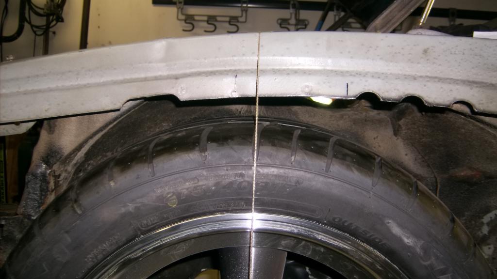
The string line is at the factory spindle CL
And 4 inches forward
Let me know what you all think of this. I am really looking for some constructive criticism and help with this.
I am going to pull the stock k member this weekend, pull the slimy engine and trans out, clean up the engine compartment, and set the 305and 4L60E from my departed 95 C1500 back in its place. I am going to bolt up my vette headers so I can make the k member fit around them and the front of the oil pan.
My approach will be a bit different as I plan on moving the spindle centerline about 4 1/2" forward. By moving the wheels forward the weight of EVERYTHING else except the front suspension moves back in relation to the wheels, not just the engine and trans, but frame, sheet metal, radiator, every other part of the car is 4 1/2" back in relation to the front wheels.
This is what you see when you look at a vette or a viper, or cobra, most of the engine if not all of the engine is behind the centerline of the front wheels. Our poor cars have almost half the engine hanging over the spindle center line.
The string line is at the factory spindle CL


And 4 inches forward

Let me know what you all think of this. I am really looking for some constructive criticism and help with this.
I am going to pull the stock k member this weekend, pull the slimy engine and trans out, clean up the engine compartment, and set the 305and 4L60E from my departed 95 C1500 back in its place. I am going to bolt up my vette headers so I can make the k member fit around them and the front of the oil pan.
Last edited by 83RDRACR; Nov 29, 2014 at 07:15 PM. Reason: repost pics

Junior Member
Joined: Sep 2014
Posts: 44
Likes: 0
Re: Home brew road racer
Awesome build thread.
On a side note, why don't most of the pictures just load. Why do you have to click on every picture. This site would be so much more enjoyable if that happened. I found myself half way through losing interest because I had to click on every picture link to see it.. Is something off in my settings?


Joined: Feb 2005
Posts: 4,505
Likes: 90
From: West Warwick RI, postal code: 02893
Car: Building LS3, T56 Z28
Engine: LS3
Transmission: T-56
Axle/Gears: Moser/ 4.11
Re: Home brew road racer
What are you going to do about fenders when the wheels are 4.5" forward?
Member
Joined: Nov 2011
Posts: 142
Likes: 0
From: Fort Gordon, GA
Car: 83 Z28
Engine: LG4
Transmission: T5
Re: Home brew road racer
Pictures work fine for me.
As for the 4.5" forward.... I can't say I'm a fan of it. I understand the intention, but think of how the wheelbase will affect the handling of the car. Also think of the work involved and the look of the fenders once you get them clearanced right.
As for the 4.5" forward.... I can't say I'm a fan of it. I understand the intention, but think of how the wheelbase will affect the handling of the car. Also think of the work involved and the look of the fenders once you get them clearanced right.
Junior Member
Joined: Sep 2014
Posts: 44
Likes: 0
Re: Home brew road racer
Pictures work fine for me.
As for the 4.5" forward.... I can't say I'm a fan of it. I understand the intention, but think of how the wheelbase will affect the handling of the car. Also think of the work involved and the look of the fenders once you get them clearanced right.
As for the 4.5" forward.... I can't say I'm a fan of it. I understand the intention, but think of how the wheelbase will affect the handling of the car. Also think of the work involved and the look of the fenders once you get them clearanced right.
All the pics show up, or you have to click the link to open the picture???
Junior Member
Joined: Sep 2014
Posts: 44
Likes: 0
Thread Starter
Senior Member
Joined: Aug 2007
Posts: 682
Likes: 45
Re: Home brew road racer
ALL THE PICS ARE DOWNLOAD FROM PHOTO BUCKET IN THE IMG FORMAT AND SHOULD VIEW WITHOUT ANY INPUT. I HAVE HAD SIMILAR TROUBLE VIEWING OTHER THREADS THOUGH
Thread Starter
Senior Member
Joined: Aug 2007
Posts: 682
Likes: 45
Re: Home brew road racer
Pictures work fine for me.
As for the 4.5" forward.... I can't say I'm a fan of it. I understand the intention, but think of how the wheelbase will affect the handling of the car. Also think of the work involved and the look of the fenders once you get them clearanced right.
As for the 4.5" forward.... I can't say I'm a fan of it. I understand the intention, but think of how the wheelbase will affect the handling of the car. Also think of the work involved and the look of the fenders once you get them clearanced right.
Thread Starter
Senior Member
Joined: Aug 2007
Posts: 682
Likes: 45
Re: Home brew road racer
Sorry about the all caps. I sent it from my phone and I locked the keyboard.
Anyway it rained all day Saturday so I got to work on the car most of the day. I cut out the upper and lower radiator supports as I will be leaning the radiator forward quite a bit and also want to be able to take the motor and trans out as one unit without having to wrestle it over the core support. I only had to raise the engine about 7 inches total to clear the front brace at sway bar level.
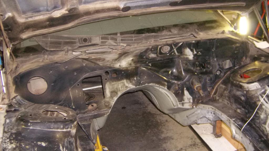
Once that was out I had the chore of degreasing the engine bay and trans tunnel. What a mess! About 3 hrs, 4 pair of latex gloves, a red scotch brite pad and a killer headache from the degreaser it started to look ok.
I promised I would weigh all of the front suspension parts and I did. I'll post the individual weights in a separate thread but it all totaled 280lbs including the k member, brakes and steering box. I also weighed the LS Camaro parts for comparison and they totaled 256lbs.
The biggest difference in weight was the steering parts, 3rd gen gear box 30lbs and steering linkage 16lbs for a total of 46lbs. The 4th gen rack weighs 24lbs. The 4th gen sway bar was also much lighter at 13lbs vs 22lbs for the 3rd gen. The 4th gen is tubular.
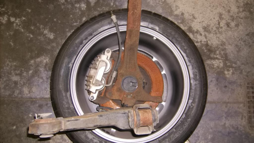
Once I got the scales put a way I checked the spindle and brake fitment in the 17x9 wheels I have. all is good with room to spare.
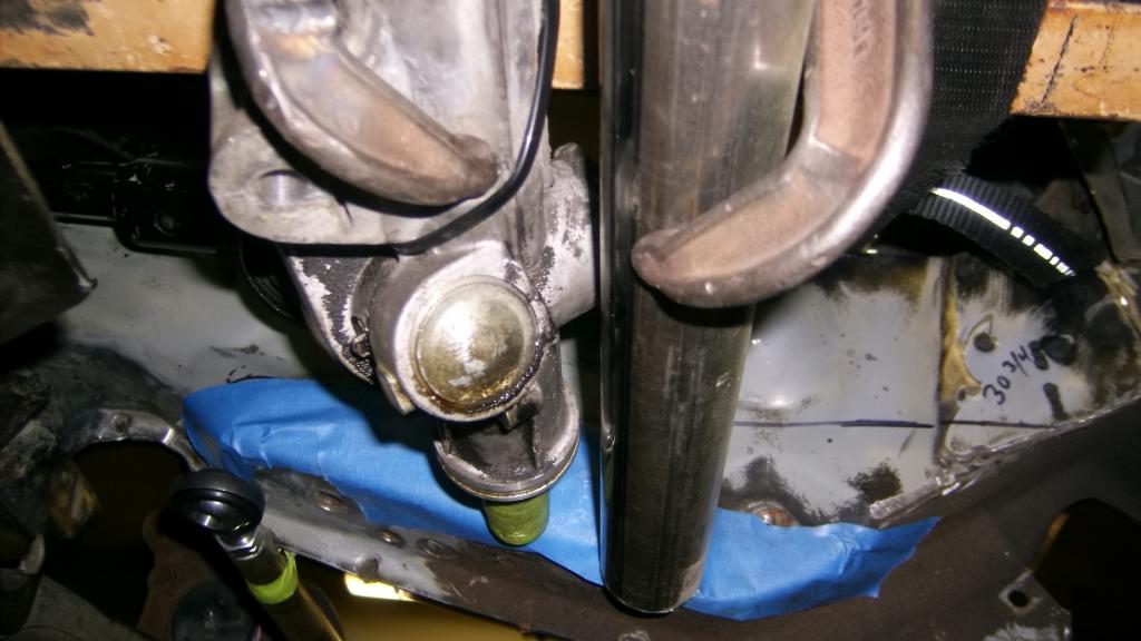
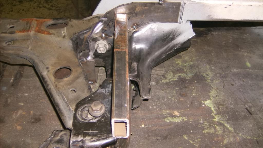
Next was to make sure the tire /wheel assembly would actually fit under the car at the desired 5" ride height. The car is mounted on 8" tall perches welded to the bottom of the sfc's. to get the tires at the correct height I trimmed a couple 2x4's to 2x3 and set them on those. lets just say we will need to trim a little.
stock position
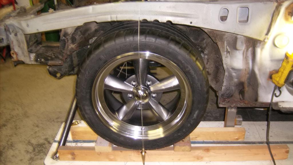
4" forward
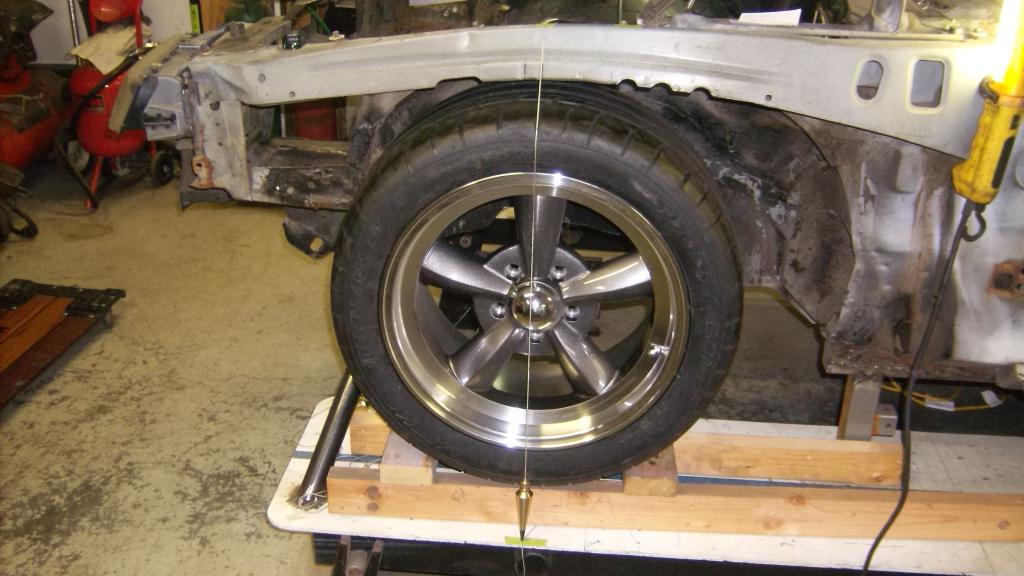
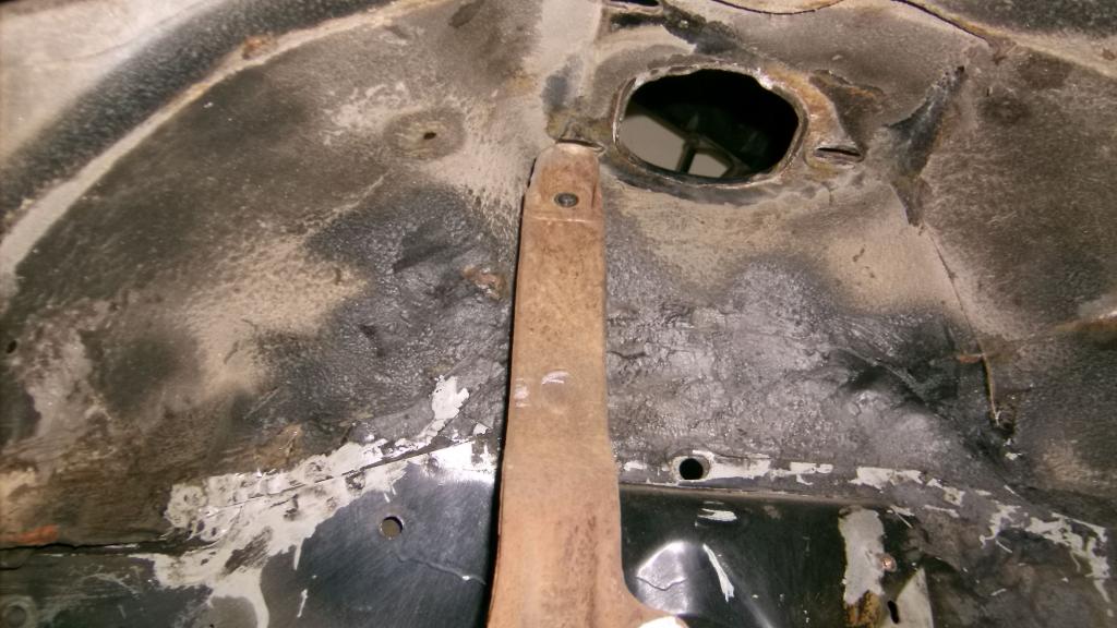
The forward position puts the front edge of tire slightly into the area ahead of the wheel well where the vapor canister sat, This will all be cut away for new wheel wells.
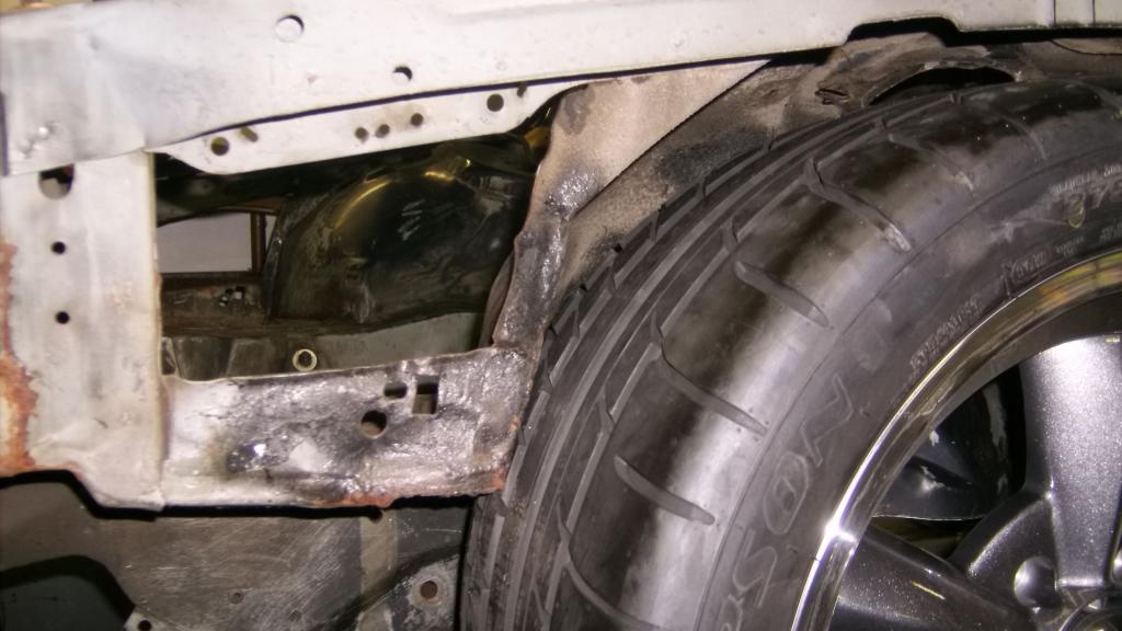
You can see how some of the sheet metal there is crumpled. This area took the brunt of the crash.
Anyway it rained all day Saturday so I got to work on the car most of the day. I cut out the upper and lower radiator supports as I will be leaning the radiator forward quite a bit and also want to be able to take the motor and trans out as one unit without having to wrestle it over the core support. I only had to raise the engine about 7 inches total to clear the front brace at sway bar level.
Once that was out I had the chore of degreasing the engine bay and trans tunnel. What a mess! About 3 hrs, 4 pair of latex gloves, a red scotch brite pad and a killer headache from the degreaser it started to look ok.

I promised I would weigh all of the front suspension parts and I did. I'll post the individual weights in a separate thread but it all totaled 280lbs including the k member, brakes and steering box. I also weighed the LS Camaro parts for comparison and they totaled 256lbs.
The biggest difference in weight was the steering parts, 3rd gen gear box 30lbs and steering linkage 16lbs for a total of 46lbs. The 4th gen rack weighs 24lbs. The 4th gen sway bar was also much lighter at 13lbs vs 22lbs for the 3rd gen. The 4th gen is tubular.
Once I got the scales put a way I checked the spindle and brake fitment in the 17x9 wheels I have. all is good with room to spare.

Next was to make sure the tire /wheel assembly would actually fit under the car at the desired 5" ride height. The car is mounted on 8" tall perches welded to the bottom of the sfc's. to get the tires at the correct height I trimmed a couple 2x4's to 2x3 and set them on those. lets just say we will need to trim a little.
stock position

4" forward


The forward position puts the front edge of tire slightly into the area ahead of the wheel well where the vapor canister sat, This will all be cut away for new wheel wells.

You can see how some of the sheet metal there is crumpled. This area took the brunt of the crash.
Last edited by 83RDRACR; Nov 29, 2014 at 07:29 PM. Reason: repost pics
Thread Starter
Senior Member
Joined: Aug 2007
Posts: 682
Likes: 45
Re: Home brew road racer
You'll notice the 4th gen spindle extends above the top of the tire. It is actually about 15" above the spindle CL. This is one of the main reasons I chose the 4th gen spindle over the more common chevelle/Camaro spindles, C5, or mustang II spindles as they are all to short for an upper A-arm to clear the frame when the suspension moves up and down. There is a thread here about a chump car build that the member races quite often and he used chevelle spindles and upper arms, but had to cut away most of the frame rail to get the needed clearance.
The top of the 4th gen spindle will be about 28" at ride height, just below the top of the factory wheel tub.
The upper a-arm and ball joint will sit about as high as the strut mount plates. I am planning on 3" of up travel so it will hopefully clear the hood!

The top of the 4th gen spindle will be about 28" at ride height, just below the top of the factory wheel tub.

The upper a-arm and ball joint will sit about as high as the strut mount plates. I am planning on 3" of up travel so it will hopefully clear the hood!

Last edited by 83RDRACR; Nov 29, 2014 at 07:37 PM. Reason: repost pics
Thread Starter
Senior Member
Joined: Aug 2007
Posts: 682
Likes: 45
Re: Home brew road racer
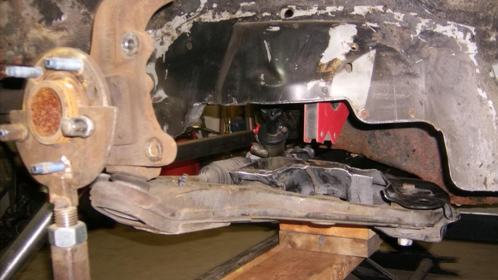
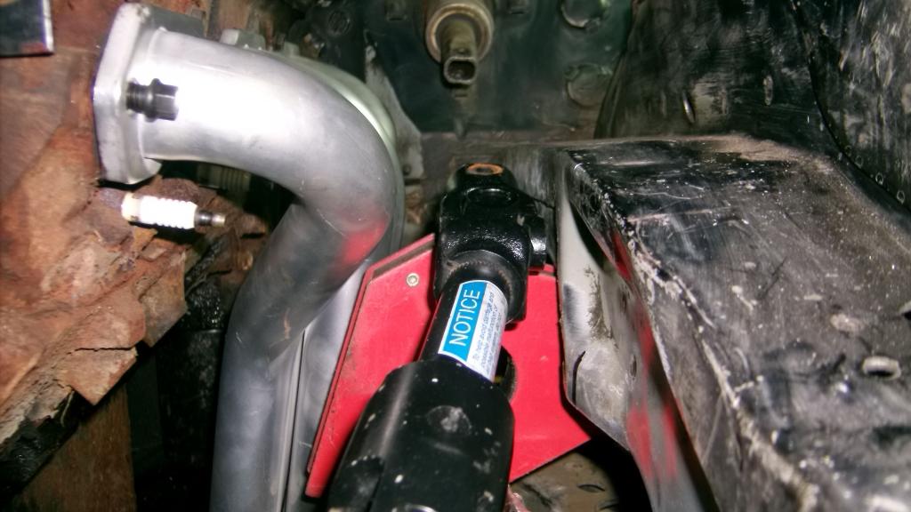
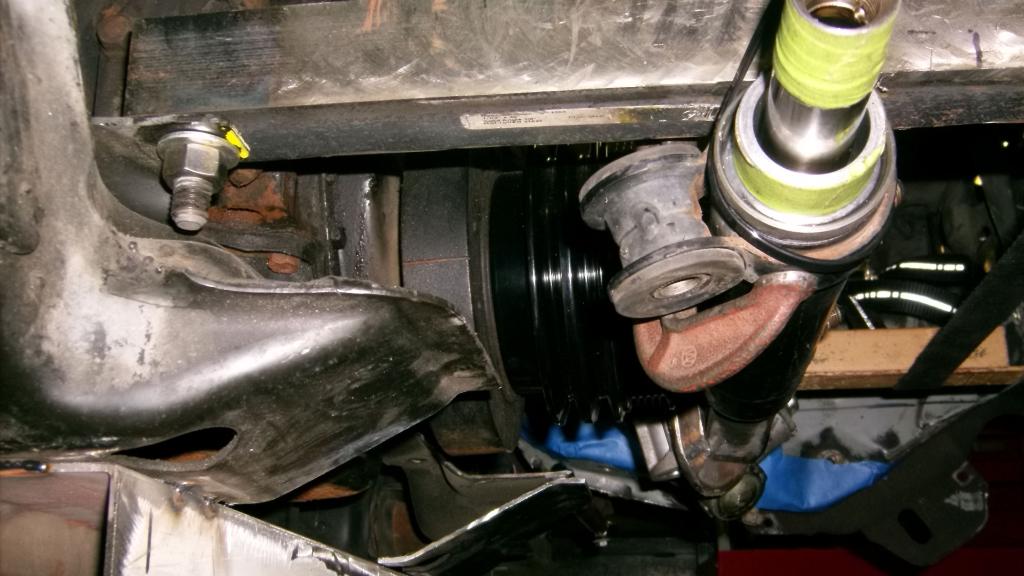
looking at the engine bay side, things seem to line up pretty good. It almost looks like GM had made the frame to fit the LCA's.
The LCA's extend into the engine bay about as far as the stock 3rd gen ones did.
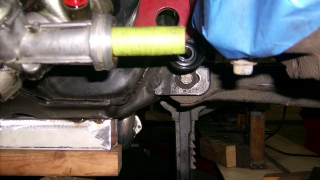
Even the rack input shaft lines up pretty well.
after looking at the last picture there may be an issue with the rack clearing the front pulleys. Notice where the brace runs just in front of and below the pulleys and then look back at where the rack is in relation to the brace.

This wasn't something I thought would be a problem. I will have to get the engine/trans back in place and see what kind of trouble I am in.

The LCA's extend into the engine bay about as far as the stock 3rd gen ones did.

Even the rack input shaft lines up pretty well.


after looking at the last picture there may be an issue with the rack clearing the front pulleys. Notice where the brace runs just in front of and below the pulleys and then look back at where the rack is in relation to the brace.
This wasn't something I thought would be a problem. I will have to get the engine/trans back in place and see what kind of trouble I am in.
Last edited by 83RDRACR; Nov 29, 2014 at 07:47 PM.
Thread Starter
Senior Member
Joined: Aug 2007
Posts: 682
Likes: 45
Re: Home brew road racer
I have gotten side tracked on a outdoor construction job that has taken up all of my spare time these last few weeks. Hopefully it will be done this weekend.
Anyway thought I would post the various weights from the suspension parts I took off. I did not take each item off separate i.e. spindle, a arm, strut etc, but rather as assemblies. I did this more for my wanting to know the difference between 3rd and 4th gen parts.
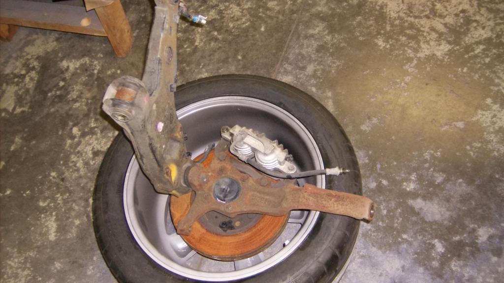
To weigh the parts and also get a total figure I set up two of my wheel scales and placed a piece of plywood on top of them and zeroed the scales with the plywood. I did not add the individual weights to get the total but rather stacked all of the parts on to the plywood once all the individual weights were taken so it may not add up exactly.
From the 83Z:
Front spindle, rotor , caliper, a-arm, strut and strut mount 77lbs per side
Steering box, includes pitman arm 30lbs
Steering linkage, includes idler arm 16lbs
Sway bar 1.25" 22lbs
coil springs 11lbs ea.
K member 46lbs no motor mounts
Total 3rd gen front suspension, brakes, steering, and K member was 280lbs.
From the 4th gen
Lower a-arm spindle and brakes 64lbs per side
shock, spring, upper a-arm and mount 28lbs per side
rack and pinion 24lbs
sway bar 1 3/8 tubular 13lbs
K member 48lbs
4th gen total 256lbs
Anyway thought I would post the various weights from the suspension parts I took off. I did not take each item off separate i.e. spindle, a arm, strut etc, but rather as assemblies. I did this more for my wanting to know the difference between 3rd and 4th gen parts.
To weigh the parts and also get a total figure I set up two of my wheel scales and placed a piece of plywood on top of them and zeroed the scales with the plywood. I did not add the individual weights to get the total but rather stacked all of the parts on to the plywood once all the individual weights were taken so it may not add up exactly.
From the 83Z:
Front spindle, rotor , caliper, a-arm, strut and strut mount 77lbs per side
Steering box, includes pitman arm 30lbs
Steering linkage, includes idler arm 16lbs
Sway bar 1.25" 22lbs
coil springs 11lbs ea.
K member 46lbs no motor mounts
Total 3rd gen front suspension, brakes, steering, and K member was 280lbs.
From the 4th gen
Lower a-arm spindle and brakes 64lbs per side
shock, spring, upper a-arm and mount 28lbs per side
rack and pinion 24lbs
sway bar 1 3/8 tubular 13lbs
K member 48lbs
4th gen total 256lbs
Thread Starter
Senior Member
Joined: Aug 2007
Posts: 682
Likes: 45
Re: Home brew road racer
From the weights I recorded you can see that the biggest weight savings, 22lbs, is getting away from the steering box and steering linkage and using the rack. The tubular sway bar saves 9lbs as well. I will also be using aluminum coil overs in place of the very long, heavy OE shocks and springs and doing away with the factory upper mounting plate. This will cut out about 18lbs per side. All total I am hoping to reduce the total weight of the entire front package by 50lbs to 60lbs.
I am not looking to save weight with the K-member. whether I build my own or modify the 4th gen to work, the K-member has to be strong and that equates to girth and weight to some extent. With all the discussions on tubular K-members I was surprised that both models weighed in under 50lbs. I was expecting something in the range of 75lbs on the 3rd gen just because it looks so massive.
Like I mentioned I have not been able to work on the car these past 2 weekends so I have not gotten the engine and trans back into the car. So not able to check fitment for the rack and pinion. I am thinking that I will probably have to mount the rack several inches forward coming off the frame rails instead of the k-member and make some kind of "Z" shaped tie rod ends to bring everything back in line.
Any suggestions on this??????
Member
Joined: May 2001
Posts: 438
Likes: 1
From: state of confusion
Car: '08 Mustang GT
Engine: 4.6L
Transmission: � � 0 . . . |-|-|
Axle/Gears: 8.8", 3.55
Re: Home brew road racer
You don't think you can mount the rack where the center link used to live?
Moving the rack forward will change the Ackermann and the bumpsteer, even without changing the rack height from the center link height.
Norm
Moving the rack forward will change the Ackermann and the bumpsteer, even without changing the rack height from the center link height.
Norm


Member
iTrader: (1)
Joined: Jul 2013
Posts: 123
Likes: 0
From: Pensacola FL
Car: 1986 Camaro Sport Coupe (Part Out)
Engine: 2.8 MPFI V6
Transmission: 700R4 Automatic 4 speed
Axle/Gears: 3.42 Open With Drum Brakes
Re: Home brew road racer
This looks like a promising build. I'll be following this.
Thread Starter
Senior Member
Joined: Aug 2007
Posts: 682
Likes: 45
Re: Home brew road racer
Norm, I have not been able to look at this since the last pictures so I don't really know what if any interference I will have. It appears though that becuase of the lower ride height the lower a-arms and rack will mount higher in relation to the crank centerline. The spindle centerline is at 13", with the lower A frame mount at about 11.5 and the rack inner pivot directly in front of that. With a 5" ride height and a 7" deep oil pan the crank center line is 12".
I did not put the rack assembly in my preliminary drawings when I was planning this out. I went back and added it in and yes it passes right through the crank pulley.
I have looked at pics on the web of 4th gen LT1 cars and the rack sit behind and below the damper. That won't work with the wheels moved forward and the frame lower on my car.
If I could mount the rack forward on the frame and make "Z" shaped tubular tie rods with outer heims I was hoping I could keep the bump and ackerman in check. The rack doesn't swing through an arc like a centerlink/gearbox system would but just moves laterally side to side.
Norm, I realize now what you were saying about changing the ackerman and bump steer. Regardless of how I would bend or shape the tie rods, if the rack attachment point is ahead of the steering arm attachment point the tie rod will still swing at an angle and in a different arc than the lower a-arm. I was just considering the back and forth travel of the rack and not the up and down movement of the tie rods.
Last edited by 83RDRACR; Nov 12, 2014 at 09:32 PM.
Thread Starter
Senior Member
Joined: Aug 2007
Posts: 682
Likes: 45
Re: Home brew road racer
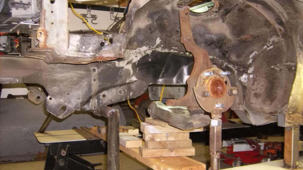
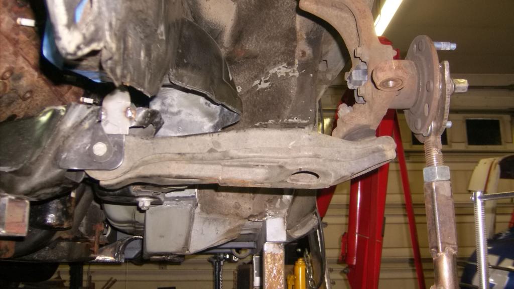
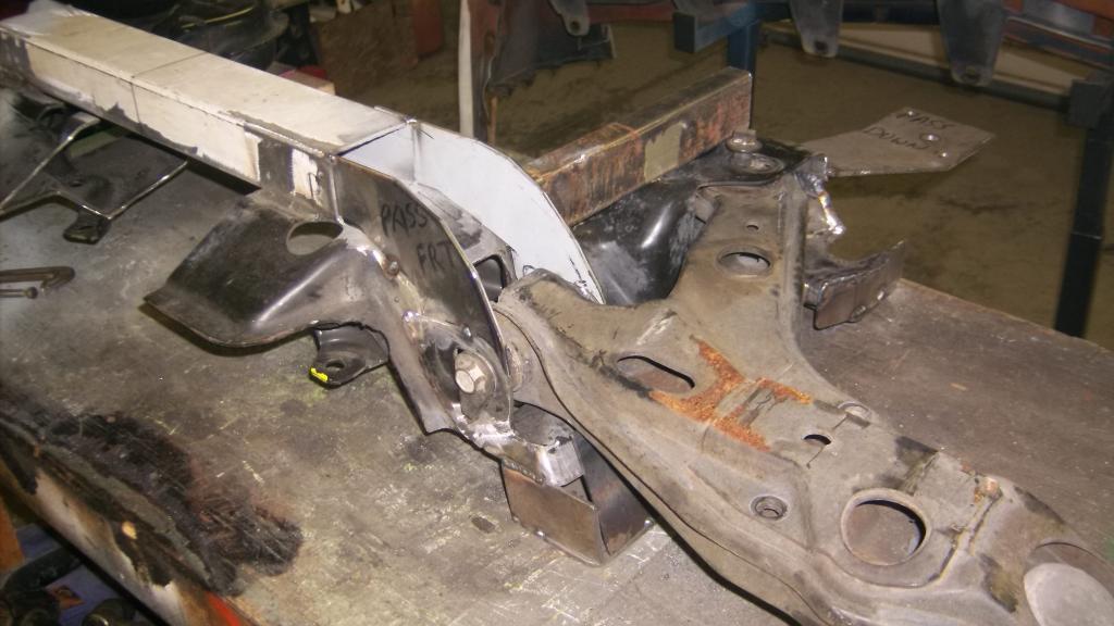
I was able to get the motor back in to check things out. To get the lower a-arms and rack in the correct alignment I needed to mount them back on the LS k-member. In order to position the K-member properly I had to cut off the top half above the lca mounts so it would not hit the 3rd gen frame rails. I put the whole deal back under the car and positioned it as close to the oil pan and damper as possible. The spindle center line is still 4" forward from stock.
Here is what I have:
With the k-member at this height the control arms angle up to the ball joint almost 10 degrees. The lca mount is almost 3" lower from where it needs to be. You can see the larger gap between the LS a-arm mount in these pics compared to the earlier mock up.
Getting the lca mounting point back into position won't be hard as the k-member can be sectioned and a drop center welded in allowing it to be raised back into position. The big problem will be relocating the rack and getting the tie rods in the correct alignment in regards to ackerman and bumpsteer.
I came across this setup from Flaming River. It uses a front steer rack mounted forward of the steering arms and uses a center link type adapter mounted behind the rack to get the tie rods inline.
http://www.flamingriver.com/index.ph.../s0014/FR355KT
In my application the tie rods would mount to the very outer edge of the center link to keep them in the stock location. The middle of the center link could curve under the damper or bend forward away from it. That's way more complex than what I initially envisioned for this mod but looks doable if that's my only option.
Here is what I have:


With the k-member at this height the control arms angle up to the ball joint almost 10 degrees. The lca mount is almost 3" lower from where it needs to be. You can see the larger gap between the LS a-arm mount in these pics compared to the earlier mock up.


Getting the lca mounting point back into position won't be hard as the k-member can be sectioned and a drop center welded in allowing it to be raised back into position. The big problem will be relocating the rack and getting the tie rods in the correct alignment in regards to ackerman and bumpsteer.
I came across this setup from Flaming River. It uses a front steer rack mounted forward of the steering arms and uses a center link type adapter mounted behind the rack to get the tie rods inline.
http://www.flamingriver.com/index.ph.../s0014/FR355KT
In my application the tie rods would mount to the very outer edge of the center link to keep them in the stock location. The middle of the center link could curve under the damper or bend forward away from it. That's way more complex than what I initially envisioned for this mod but looks doable if that's my only option.

Junior Member
Joined: Apr 2013
Posts: 35
Likes: 0
From: palm coast fl
Car: 85 iroc
Engine: 357
Transmission: th400
Axle/Gears: 8.5 10 bolt 373 with lift bars
Re: Home brew road racer
hey I was just reading up on your build , I can tell you from experience what will fit I too was searching for a rear for my iroc .I went to a wrecking yard and found out the 8.5 out of a second gen f body was only 5/16th shorter . I cut all of the mounts of my 7.5 and that's whats in there now .
Thread Starter
Senior Member
Joined: Aug 2007
Posts: 682
Likes: 45
Re: Home brew road racer
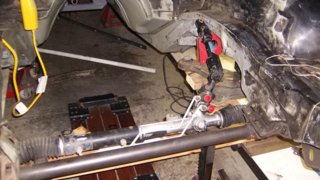
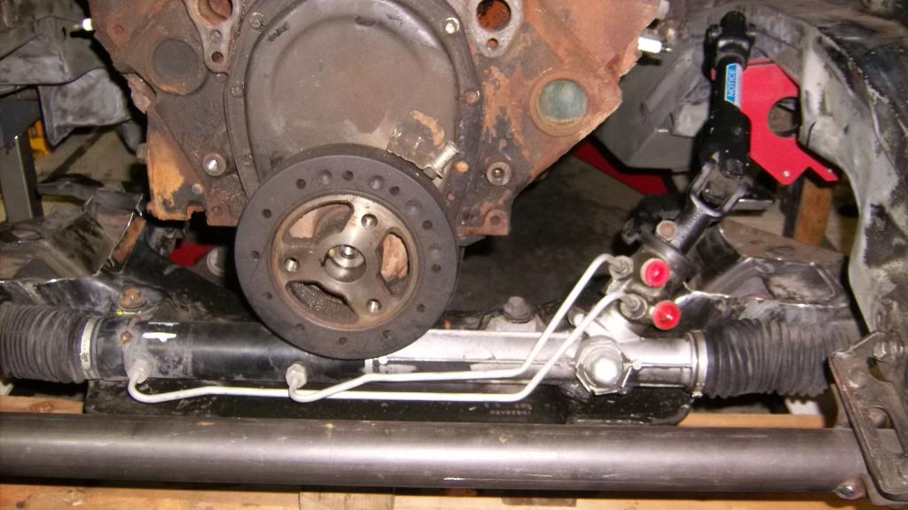
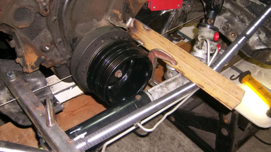
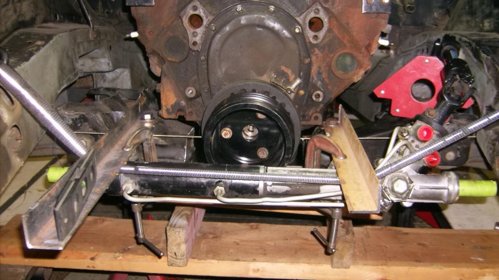
I modified the k-member so I could get the lca's back into position. Also removed the inner and outer tie rods from the rack so it would fit between the frame rails. Here is what I am faced with.
k-member back in place. I purposely left the rack mounts on so I could use them as a guide to line up the rack farther forward.

Bare rack 27" overall length, about 3" shorter than the distance between the rails.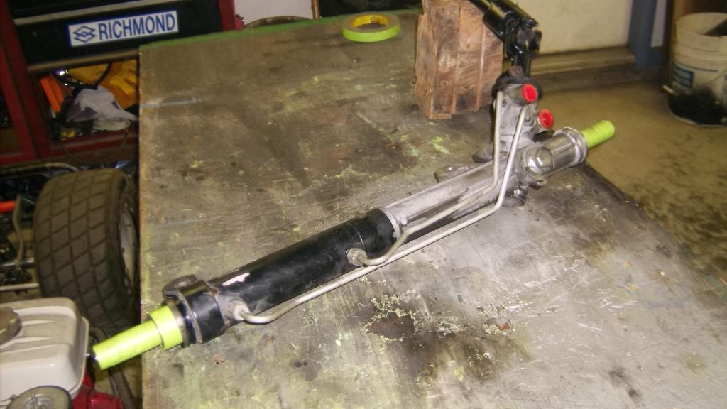
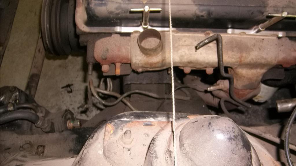
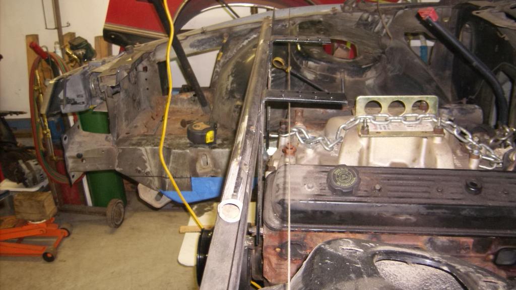
Rack is close to position in frame where it would have to sit. String line is through steering arms and shows where rack would normally sit. Center line of rack would be about 8 1/2" forward of string line.
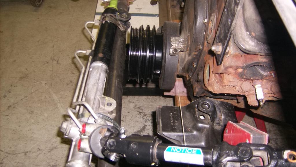
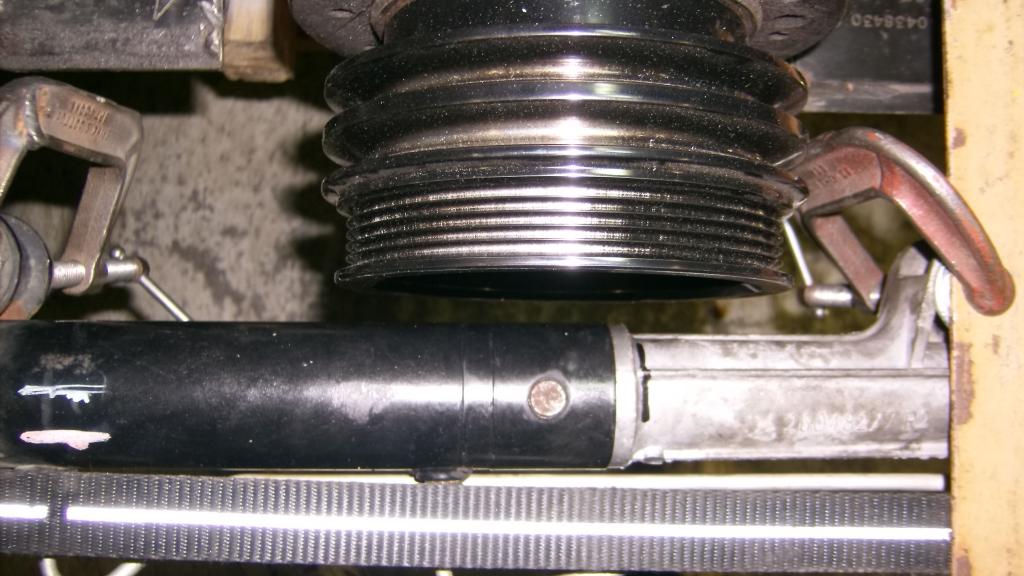
The black, triple pulley is for a '80 to '85 sbc with a long water pump and a/c. It is from a March pulley kit. This is the set up I was hoping to run. If I ditch the a/c and run a short pump I can move the rack closer to the engine by about 1 3/4". I think i'll need about 1" clearance between front edge of pulley and the outer edge of the rack mounting bosses for the "centerlink" to pass through.
And a view from the front.
k-member back in place. I purposely left the rack mounts on so I could use them as a guide to line up the rack farther forward.

Bare rack 27" overall length, about 3" shorter than the distance between the rails.

Rack is close to position in frame where it would have to sit. String line is through steering arms and shows where rack would normally sit. Center line of rack would be about 8 1/2" forward of string line.

The black, triple pulley is for a '80 to '85 sbc with a long water pump and a/c. It is from a March pulley kit. This is the set up I was hoping to run. If I ditch the a/c and run a short pump I can move the rack closer to the engine by about 1 3/4". I think i'll need about 1" clearance between front edge of pulley and the outer edge of the rack mounting bosses for the "centerlink" to pass through.
And a view from the front.

Junior Member
Joined: Apr 2013
Posts: 35
Likes: 0
From: palm coast fl
Car: 85 iroc
Engine: 357
Transmission: th400
Axle/Gears: 8.5 10 bolt 373 with lift bars
Re: Home brew road racer
i like the build is it almost ready to come of the jig yet? i have pictures o the rear in my iroc but i am still trying to figure so things out with this sight .I find myself reading things from years ago . this is giving me ideas for what to do with my gta it got rear ended by a girl texting . she folded the frame rail , every thing from rear seats back is twisted floor , rear left quarter ,
fuel tank everything. I was going to restore it because it was all original\
right down to the battery . it just opens the door for me to go crazy now.
fuel tank everything. I was going to restore it because it was all original\
right down to the battery . it just opens the door for me to go crazy now.
Thread Starter
Senior Member
Joined: Aug 2007
Posts: 682
Likes: 45
Re: Home brew road racer
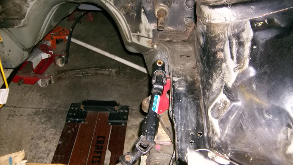
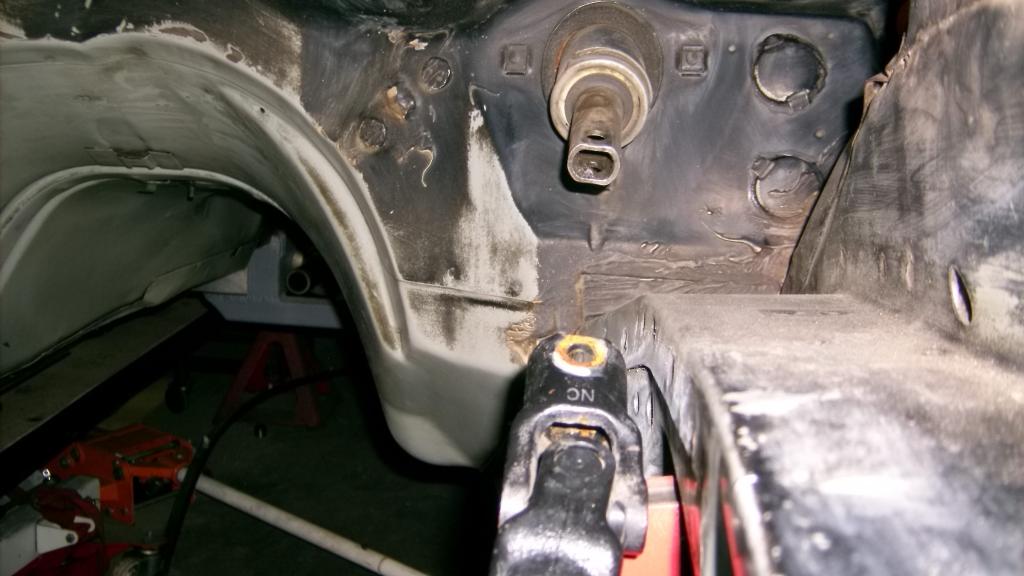
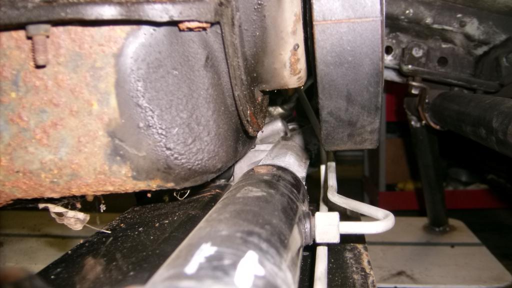
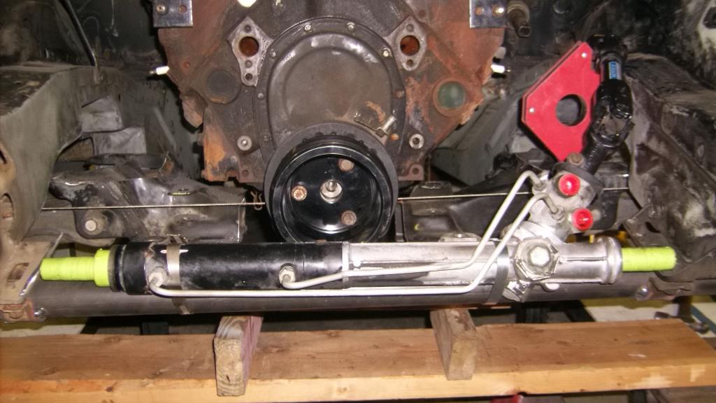
I took a leap of faith and removed the front cross brace that held the front frame rails in place. To my great relief nothing moved! With that out of the way I was able to locate the rack pretty close to where it would have to sit ahead of the engine.

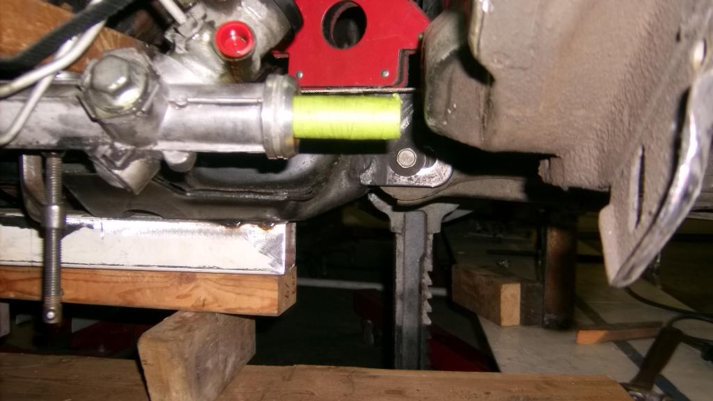
This last picture you can see that I am pretty well lined up with the lower lca mounting point. This is key to keeping bump steer to a minimum. I have sketched out several ideas that would keep the tie rods running in the same plane as original. The best one so far has the rack up close to the motor as pictured with 6'' extensions coming back off the rack and a connecting link running under the pulleys and damper.
I'll try to get a simple drawing posted and hopefully get some feedback about any geometry or strength issues.
Thread Starter
Senior Member
Joined: Aug 2007
Posts: 682
Likes: 45
Re: Home brew road racer
looking at the engine bay side, things seem to line up pretty good. It almost looks like GM had made the frame to fit the LCA's.

The LCA's extend into the engine bay about as far as the stock 3rd gen ones did.

Even the rack input shaft lines up pretty well.


after looking at the last picture there may be an issue with the rack clearing the front pulleys. Notice where the brace runs just in front of and below the pulleys and then look back at where the rack is in relation to the brace.

This wasn't something I thought would be a problem. I will have to get the engine/trans back in place and see what kind of trouble I am in.
Thread Starter
Senior Member
Joined: Aug 2007
Posts: 682
Likes: 45
Re: Home brew road racer
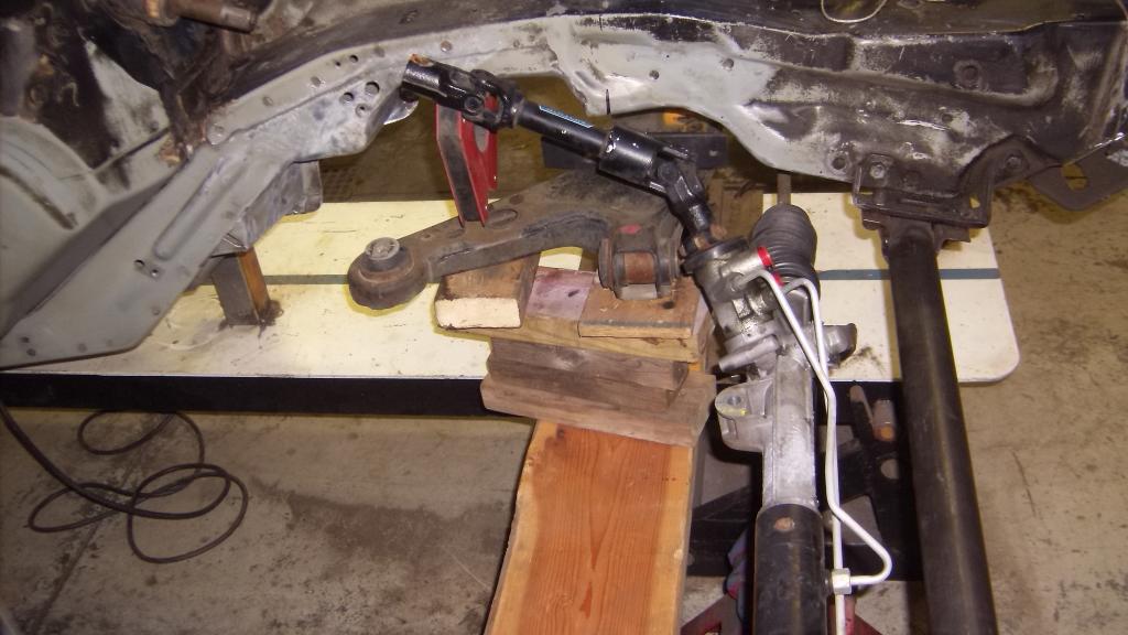
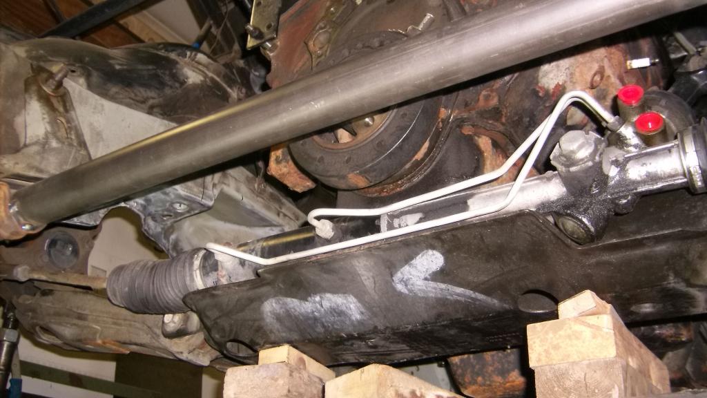
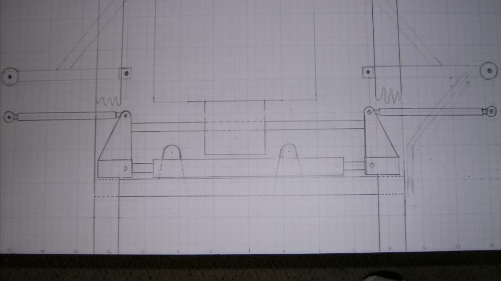
After taking more measurements and making a couple scale drawings and some more observations I have come to the conclusion that moving the front wheels up another inch will alleviate some of the fitment issues. Also I found that rotating the rack about 30 degrees to the rear allows me to get the cross member that the rack will mount to closer to the rack and improves the steering shaft alignment. Now the front cross member will also be the mount for a NASCAR styled splined sway bar. The splined bars are 37.5" long and the frame rails are 36" wide to the outside.
with the rack mounted in the straight up position the steel pressure lines extend about 2 inches forward forcing the locaton of the front crossmember farther forward. This would make for a 15" arm from sway bar to lower a-arm.
Rotating the rack about 30 degrees moves the lines up out of the way letting the front crossmember to mount very close to the rack. This and moving the wheels forward another inch reduce the sway bar arm length to 12".
 .
.
I dropped the left header in place to check for steering shaft clearance. Looks good!
 .
.
with the rack mounted in the straight up position the steel pressure lines extend about 2 inches forward forcing the locaton of the front crossmember farther forward. This would make for a 15" arm from sway bar to lower a-arm.

Rotating the rack about 30 degrees moves the lines up out of the way letting the front crossmember to mount very close to the rack. This and moving the wheels forward another inch reduce the sway bar arm length to 12".
 .
.I dropped the left header in place to check for steering shaft clearance. Looks good!
 .
. Thread Starter
Senior Member
Joined: Aug 2007
Posts: 682
Likes: 45
Re: Home brew road racer
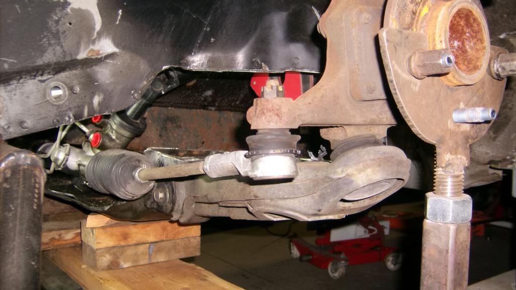
Tie rods are 5/8 x 11 tubes from Afco with QA1 PC rod ends 5/8 thread with 1/2" hole. The PC series allow for 20 degree mis alignment where the slightly stronger X series only allows for 10 degrees. The steering arms will get drilled out and I will be able to use spacers/washers to adjust for bump steer.
Alignment between LCA mount, tie rod end and rack.

Alignment between LCA mount, tie rod end and rack.

Thread Starter
Senior Member
Joined: Aug 2007
Posts: 682
Likes: 45
Re: Home brew road racer
here is a pic from the passenger side. You can see the slight downward angle of the rack mount. You can also see the end of the rack where the stock tie rod threaded into. The thread is 18m x 1.5, same as on O2 sensor. This is where I will have to attach my extensions to get the tie rods to realign with the steering arms.
Here is my biggest concern: The rack shaft is .990" diameter and the 18mm thread is just shy of 3/4". this leaves a very thin wall around the threads. This was not a concern in the factory application because the forces on the rack were straight through the shaft. In my setup there will be a 5" extension bolted to the end of the rack that will create a 5" lever arm that will apply significant side loads.
I am hoping that the center connecting link will carry most of the force and keep the end of the rack from bending or more likely cracking at the threads. This is where I am hoping Norm and the other engineer types out there can help me with a design to safely get this done. This will make or break this front end conversion.

Here is my biggest concern: The rack shaft is .990" diameter and the 18mm thread is just shy of 3/4". this leaves a very thin wall around the threads. This was not a concern in the factory application because the forces on the rack were straight through the shaft. In my setup there will be a 5" extension bolted to the end of the rack that will create a 5" lever arm that will apply significant side loads.

I am hoping that the center connecting link will carry most of the force and keep the end of the rack from bending or more likely cracking at the threads. This is where I am hoping Norm and the other engineer types out there can help me with a design to safely get this done. This will make or break this front end conversion.

Member
Joined: Oct 2011
Posts: 226
Likes: 0
From: Black Hills
Car: 88 rs
Engine: ls1
Transmission: t56
Axle/Gears: moser 4:10
Re: Home brew road racer
One other thing you need to consider. In that configuration you will need to control the rack shaft to keep it from trying to rotate in the housing.
Thread Starter
Senior Member
Joined: Aug 2007
Posts: 682
Likes: 45
Re: Home brew road racer
The connecting link will have to pass under the balancer. It will need to drop down about 3 inches from the height of the tie rods. The Flaming River rack I referred to earlier uses some type of urethane coated rollers. They are mounted above and below the cross bar and centered on the rack. I am also thinking of putting in a threaded adjustment link on the driver side so I can give the cross bar a slight preload after it is installed
The rack only travels 2 3/8" from center to lock in either direction so my extensions won't interfere with the P/S pump or alternator and I have ample room to make a gradual turn down to get the cross bar under the damper.
I also want to tell you again how much I admired your LS road racer build. The level of craftsman ship on that was amazing and the fact that you completed it in about a years time really makes my project pale in comparison.
Thread Starter
Senior Member
Joined: Aug 2007
Posts: 682
Likes: 45
Re: Home brew road racer
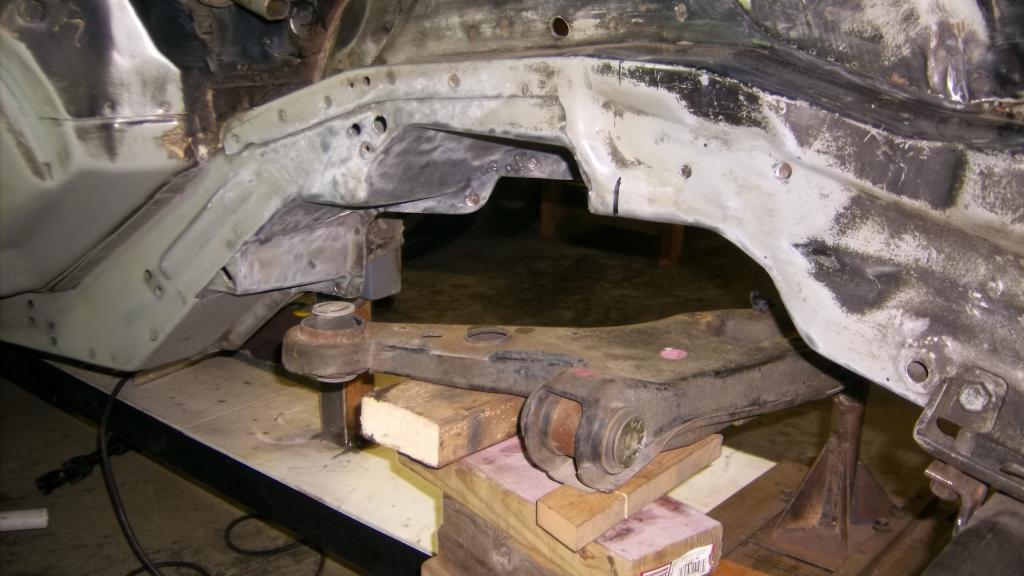
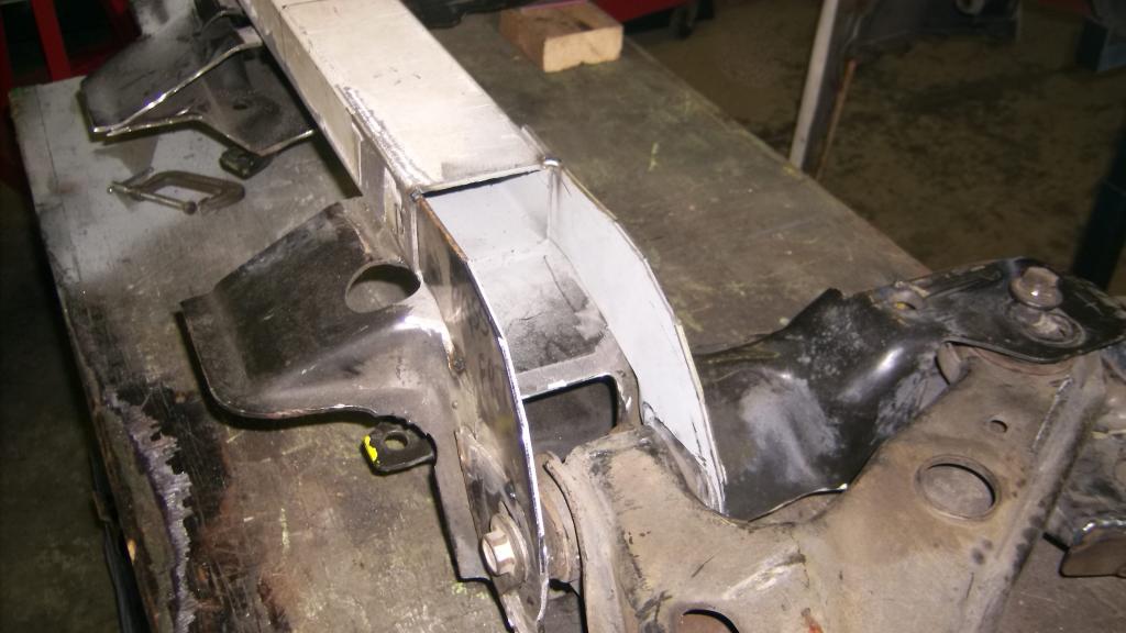
I am moving ahead with the k member install, confident that the rack issue can be solved. Up to now the k member was propped on boards to get it in the approximate location to see if it was feasible to use this front end. Now that I know it will work it was time to get it level and centered and locked in to place.
To level the k member I used the lca front mounting bolts as my reference point as that is the critical dimension. These have to be the same height as the center of the lower ball joint at ride height. Getting the exact center is difficult as the pivot ball is not accessible, so after taking multiple measurements uh, guestimates, I settled on 11.5" with the spindle height at 13".
Earlier, before I modified the k member by cutting out the center, I located and marked the centerline of the k member using the distance between the front lca mounting holes. I transferred that centerline to the 2x3 tubing I welded to the bottom. So with a centerline and a height dimension, two plum bobs, tape measures and a couple of levels I got the k member in place.
To hold it there I fabbed 4 simple metal straps and tacked them to the frame rails.


Member


Joined: Jun 2013
Posts: 497
Likes: 4
From: El Sobrante, California
Car: 1984 z28
Engine: Crate replacement L31R 350
Transmission: T56
Axle/Gears: 7.625" 28 spline 3.23
Re: Home brew road racer
Re: Home brew road racer
That's correct. We, ThirdGen.org staff, have not altered or deleted the pictures being posted as we have no control over the content outside of ThirdGen and the pictures posted by the author are on Photobucket. This is Photobucket's side. The person who has control over the album has either moved, deleted, or set private the pictures.
Thread Starter
Senior Member
Joined: Aug 2007
Posts: 682
Likes: 45
Re: Home brew road racer
Thanks for the quick reply and you are correct. I moved the pictures from the main library to a separate album just for the front end fabrication. I didn't realize that would affect previous postings.
Thread Starter
Senior Member
Joined: Aug 2007
Posts: 682
Likes: 45
Re: Home brew road racer
I got cut short on my last picture post as it was time to leave for Thanksgiving dinner.
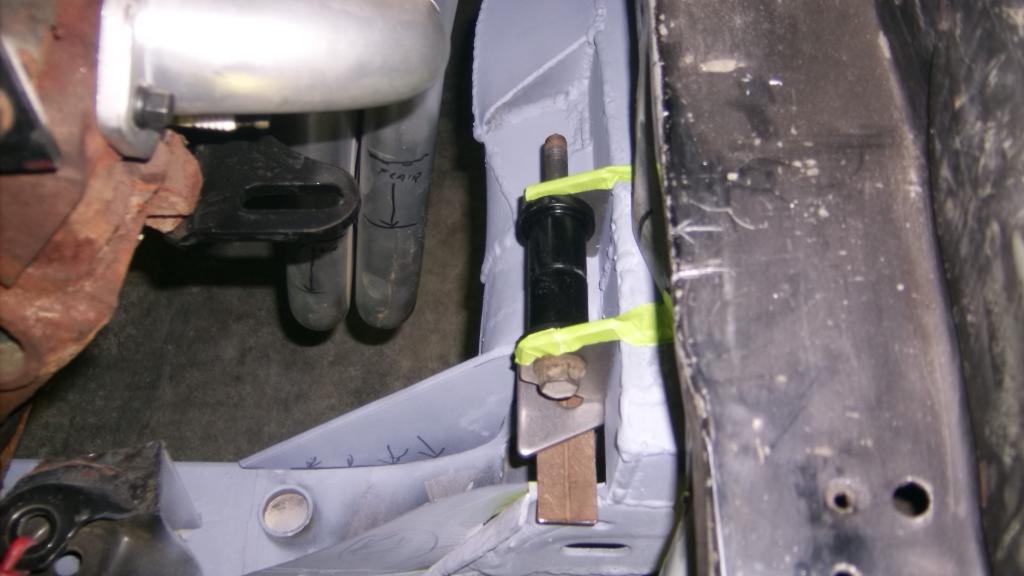
To get the rear of the k member level was also a little tricky as the pivot bolt is vertical and not horizontal like the front. I needed to find something on the LCA that was level in a front to back direction that I could set a level on. I settled on using the two small mounting pads that the stock LS strut mounts to.
I was holding the back of the k member up with jack stands and I used strips of scrap metal as shims to raise the rear of the k member till the bubble was centered. I tacked small bracket to inner fender to hold the position.
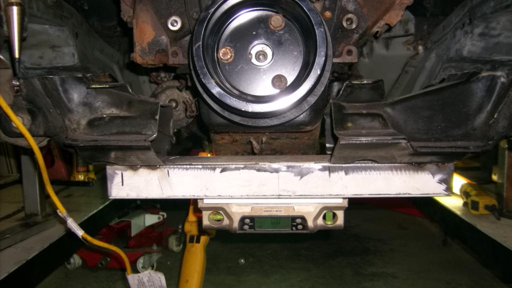
Now the k member is secured in position with the front wheel center line 5" forward from stock. When I first thought about moving the front end forward my measurements told me 5" was doable and maybe even easier than just moving it out 4". As it turns out, moving it forward 5" is my best option with using the 4th gen components.
With CL 5" forward spindle is inline with #1 exhaust port.
To get the rear of the k member level was also a little tricky as the pivot bolt is vertical and not horizontal like the front. I needed to find something on the LCA that was level in a front to back direction that I could set a level on. I settled on using the two small mounting pads that the stock LS strut mounts to.

I was holding the back of the k member up with jack stands and I used strips of scrap metal as shims to raise the rear of the k member till the bubble was centered. I tacked small bracket to inner fender to hold the position.

Now the k member is secured in position with the front wheel center line 5" forward from stock. When I first thought about moving the front end forward my measurements told me 5" was doable and maybe even easier than just moving it out 4". As it turns out, moving it forward 5" is my best option with using the 4th gen components.
With CL 5" forward spindle is inline with #1 exhaust port.

Last edited by 83RDRACR; Nov 29, 2014 at 08:49 PM. Reason: add pics
Thread Starter
Senior Member
Joined: Aug 2007
Posts: 682
Likes: 45
Re: Home brew road racer
With the k member held up by the straps I was able to get rid of the wood that was propping it up. I double checked the LCA and lower ball joint height and rechecked the k member center line. All were spot on. This was something I was not sure I could do when I started this front end conversion. To take something as oddly shaped as the LS k member and get it centered and level at an exact height between two frame rails that have almost no symmetry took way more thought and effort than the rear suspension did.
I have literally spent hours looking, measuring, imagining and making sketches in an effort to realize what were the important locating points and where those points needed to be. Having the car mounted to the ramps and being able to secure the spindles in my make shift holders were key to getting accurate, consistent and repeatable measurements.
Here is what it looks like:
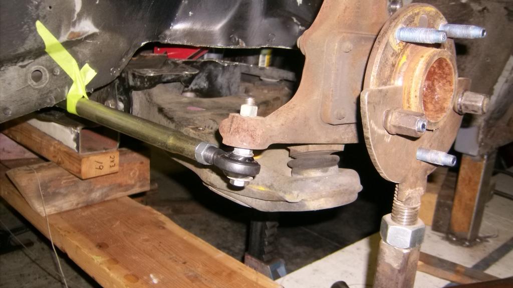
Final spindle location with 7* caster
Lower control arm with 0* camber
I had noticed the odd angle of the lower ball joint in the control arm, and originally thought that the arm had to run up hill from ball joint to k member to get the ball joint stud perpendicular. Looking closer the bottom of the spindle is cast at an angle so the a arm is level and the ball joint stud mounts to the spindle on an angle. I believe GM did this to decrease the scrub radius.
This is a pic of the rear most k member mount. The LS k member mounting hole is only off by about a 1/2".
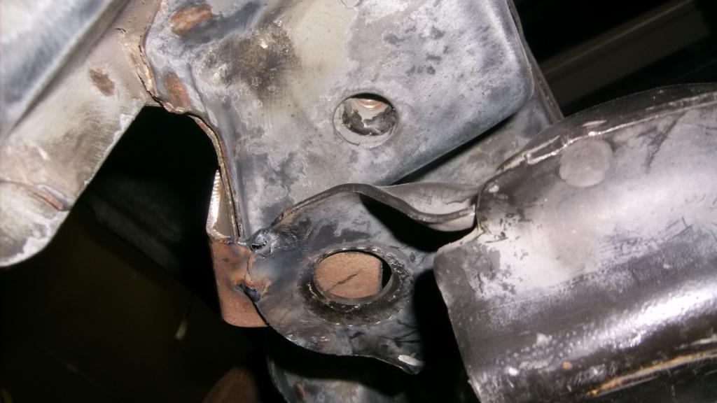
The front mounting bolt location is almost centered above front lca mount.
Now I have to get busy make some good solid mounts for the k member. I am not a big fan of bolt in k members. They only exist because it makes production line assembly easier. I do not believe they provide the torsional rigidity of a welded k member. That being said I am initially going to make tis a bolt in k member as I am sure I will be making changes, uh refinements to it once it hits the road.
I have literally spent hours looking, measuring, imagining and making sketches in an effort to realize what were the important locating points and where those points needed to be. Having the car mounted to the ramps and being able to secure the spindles in my make shift holders were key to getting accurate, consistent and repeatable measurements.
Here is what it looks like:
Final spindle location with 7* caster

Lower control arm with 0* camber

I had noticed the odd angle of the lower ball joint in the control arm, and originally thought that the arm had to run up hill from ball joint to k member to get the ball joint stud perpendicular. Looking closer the bottom of the spindle is cast at an angle so the a arm is level and the ball joint stud mounts to the spindle on an angle. I believe GM did this to decrease the scrub radius.
This is a pic of the rear most k member mount. The LS k member mounting hole is only off by about a 1/2".

The front mounting bolt location is almost centered above front lca mount.

Now I have to get busy make some good solid mounts for the k member. I am not a big fan of bolt in k members. They only exist because it makes production line assembly easier. I do not believe they provide the torsional rigidity of a welded k member. That being said I am initially going to make tis a bolt in k member as I am sure I will be making changes, uh refinements to it once it hits the road.
Thread Starter
Senior Member
Joined: Aug 2007
Posts: 682
Likes: 45
Re: Home brew road racer
To mount the k member I started out making 6 plates that would bolt up in the 3rd gen frame rails. Again no symmetry so 6 different poster board templates and then 6 different steel plates. Plates are 3/16".
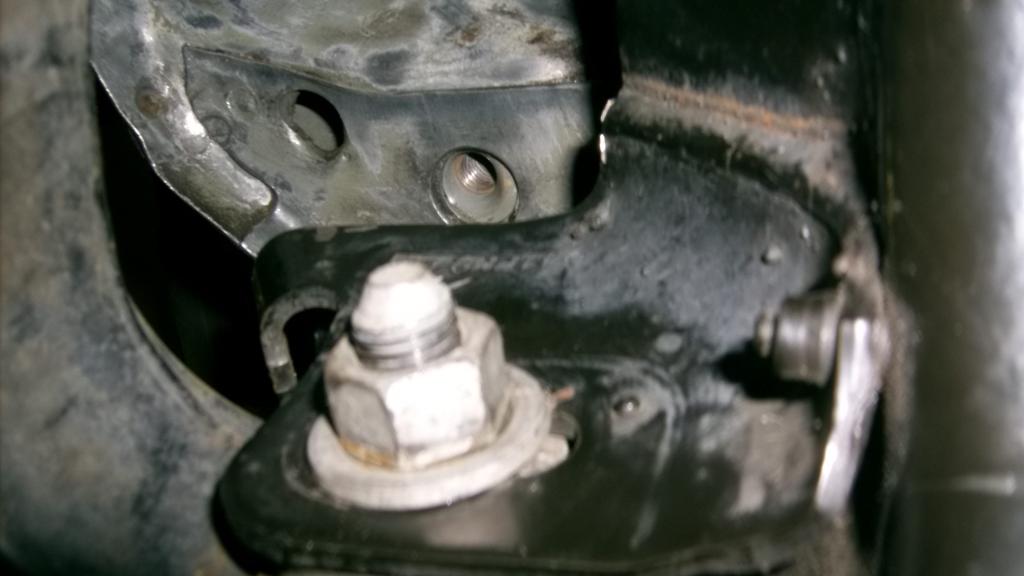
Here are the back two on passenger side.
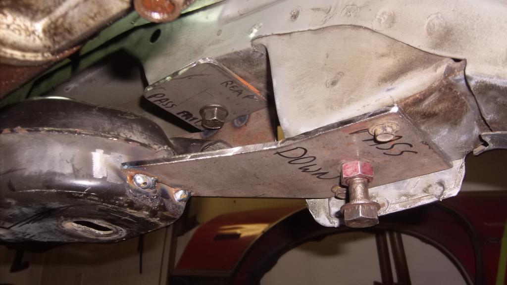
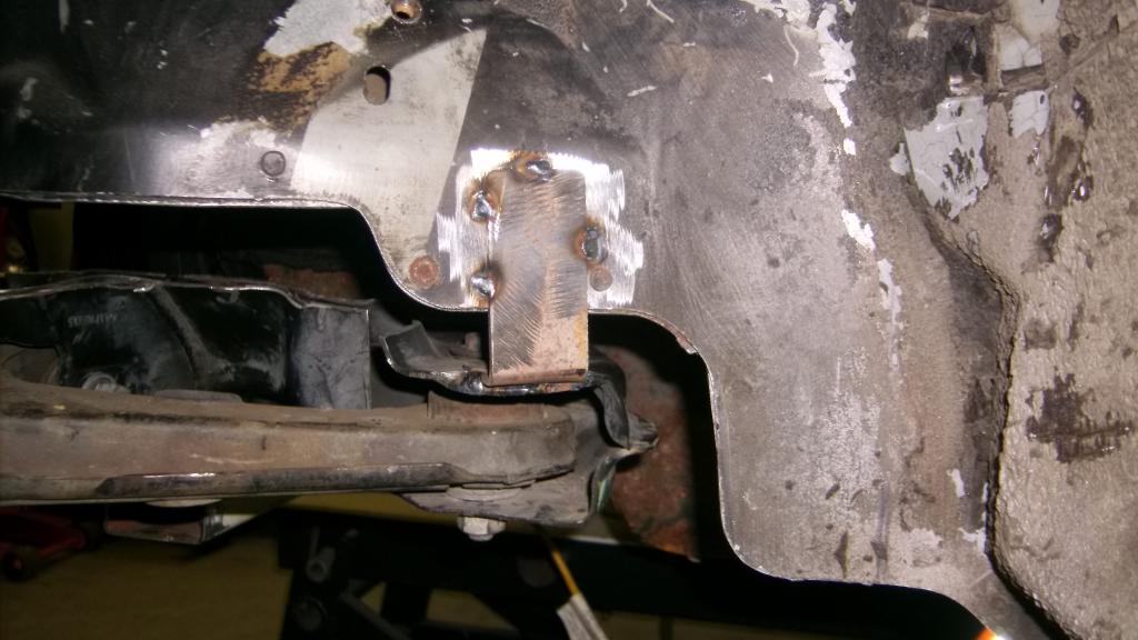
The rear bracket is about 5" long. In the pic it looks like the front is bent upward but the plate is straight, just cut at an angle. The two small bolts are t0 index the k member so it always goes back in in the same spot. These are needed because the nuts up in the chassis float and the k member could get installed slightly skewed. The factory used alignment pins that went into small holes just ahead of the front mounting bolts.
Next I cut and fitted 1/8" plate between the k member and the 3/16 plates bolted to the frame rails.
I put in as many as I could get to with the welder. I pulled the k member back out and will finish it on the weld table. This will take some time.
You are probably thinking this is the worst looking, pieced together, pile of junk ever posted on this site and I would not disagree. But this is only temporary. About 90% of the LS crossmember will be cut away, I will only be keeping the LCA mounts. With the k member having to be raised to get the proper alignment, the bottom surface of the LS k member will actually become the top surface.
Here is what the bottom of the k member will look like.
Let me know what you think. I could be all wrong about this.
Here are the back two on passenger side.

The rear bracket is about 5" long. In the pic it looks like the front is bent upward but the plate is straight, just cut at an angle. The two small bolts are t0 index the k member so it always goes back in in the same spot. These are needed because the nuts up in the chassis float and the k member could get installed slightly skewed. The factory used alignment pins that went into small holes just ahead of the front mounting bolts.
Next I cut and fitted 1/8" plate between the k member and the 3/16 plates bolted to the frame rails.

I put in as many as I could get to with the welder. I pulled the k member back out and will finish it on the weld table. This will take some time.


You are probably thinking this is the worst looking, pieced together, pile of junk ever posted on this site and I would not disagree. But this is only temporary. About 90% of the LS crossmember will be cut away, I will only be keeping the LCA mounts. With the k member having to be raised to get the proper alignment, the bottom surface of the LS k member will actually become the top surface.
Here is what the bottom of the k member will look like.


Let me know what you think. I could be all wrong about this.
Last edited by 83RDRACR; Nov 29, 2014 at 10:49 PM. Reason: added more info
Thread Starter
Senior Member
Joined: Aug 2007
Posts: 682
Likes: 45
Re: Home brew road racer
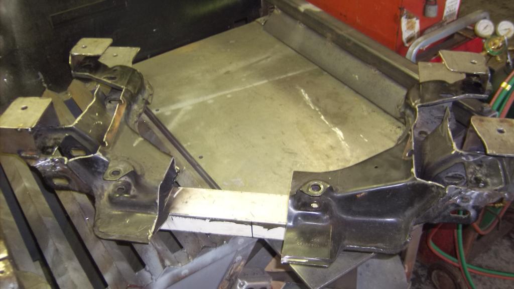
Here is the k member with the 1/8" steel plating.
here you can see that the bottom surface of the LS k member is now going to be the top side. (k member is upside down in pic)
To gain clearance for the headers and starter I cut out the inner wall and replated with more 1/8".
as you can see here this gave me an additional 1 1/2" clearance.
Since I cut away most of the structure that tied the front and rear a-arm mounts together I will tie the two back together with some 1x2 tubing something like this.
I'll add a diagonal brace from the 1x2 back to the crossmember. I'll wait till it is back under the car so I make sure it clears the oil pan and headers.
While the k member was upside down on the bench I leveled the crossmember and one of the a-arms and measured the angle of the lower ball joint. The ball joint is angled in at the top 20* from vertical. Again, I think GM did this to decrease the scrub radius for better cornering.

here you can see that the bottom surface of the LS k member is now going to be the top side. (k member is upside down in pic)

To gain clearance for the headers and starter I cut out the inner wall and replated with more 1/8".

as you can see here this gave me an additional 1 1/2" clearance.

Since I cut away most of the structure that tied the front and rear a-arm mounts together I will tie the two back together with some 1x2 tubing something like this.

I'll add a diagonal brace from the 1x2 back to the crossmember. I'll wait till it is back under the car so I make sure it clears the oil pan and headers.

While the k member was upside down on the bench I leveled the crossmember and one of the a-arms and measured the angle of the lower ball joint. The ball joint is angled in at the top 20* from vertical. Again, I think GM did this to decrease the scrub radius for better cornering.

Thread Starter
Senior Member
Joined: Aug 2007
Posts: 682
Likes: 45
Re: Home brew road racer
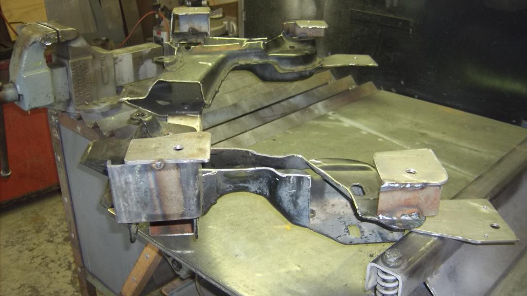
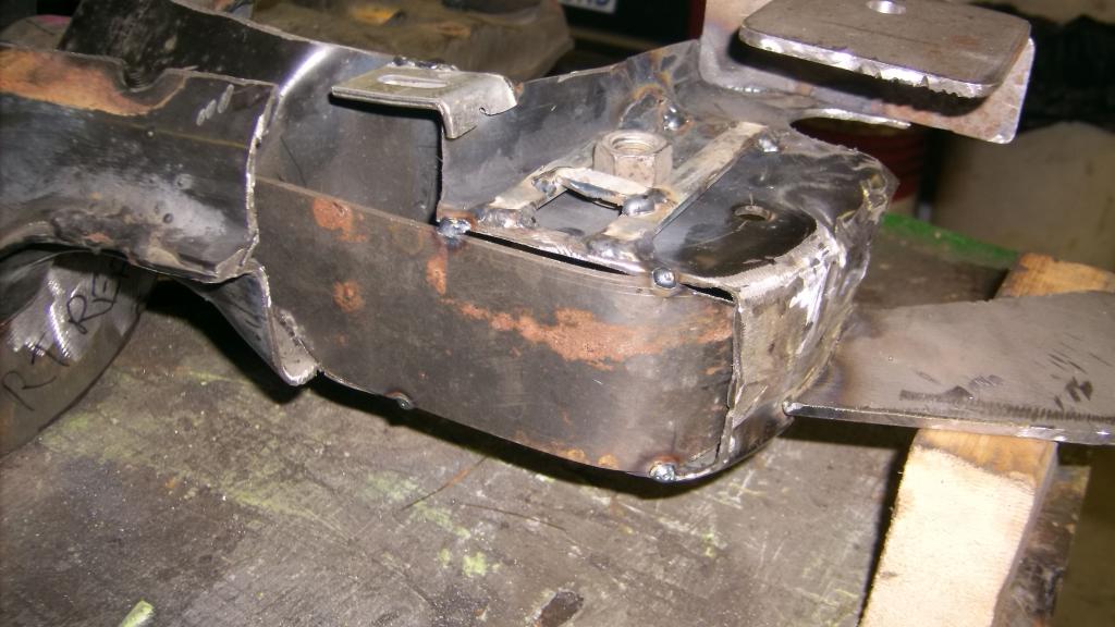
I finally have some time to post progress on the k-member. it is almost done. I went ahead and sprayed some rattle can primer on it as the bare metal didn't show much detail. All of the new metal is 1/8 or 3/16 steel and seams are welded both sides if there was access.
As you can see there is not much left of the stock 4th gen k-member. I am not sure if the 1x2 lower brace is needed but decided to keep it as I need a place to attach lower diagonal braces.
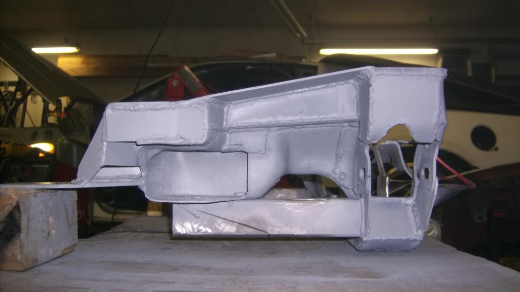
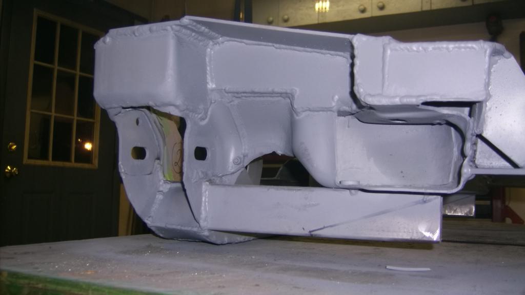
As you can see there is not much left of the stock 4th gen k-member. I am not sure if the 1x2 lower brace is needed but decided to keep it as I need a place to attach lower diagonal braces.


Thread Starter
Senior Member
Joined: Aug 2007
Posts: 682
Likes: 45
Re: Home brew road racer
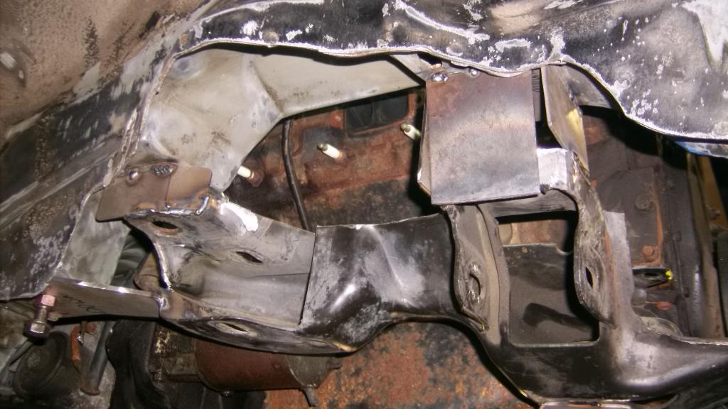
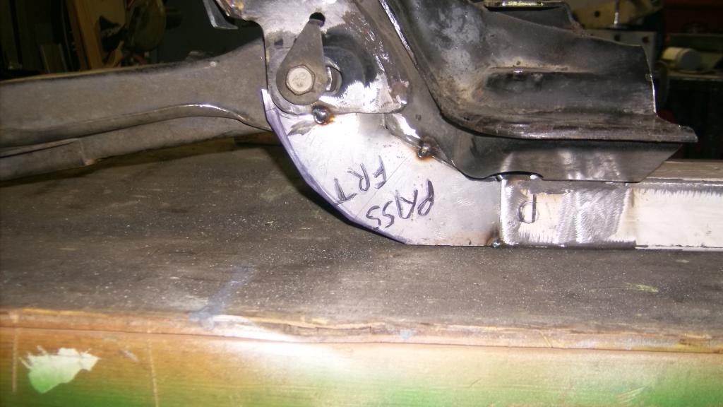
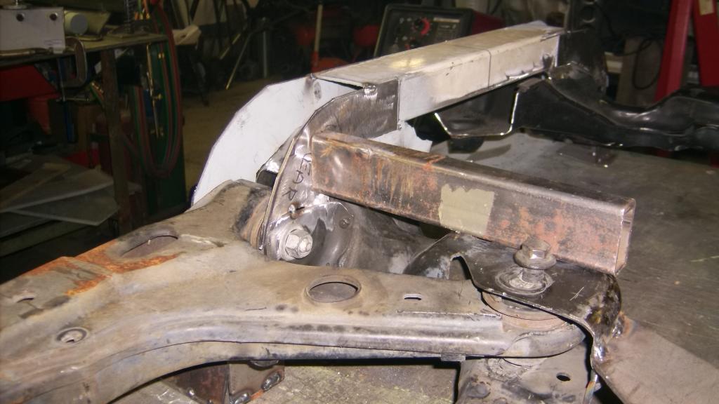
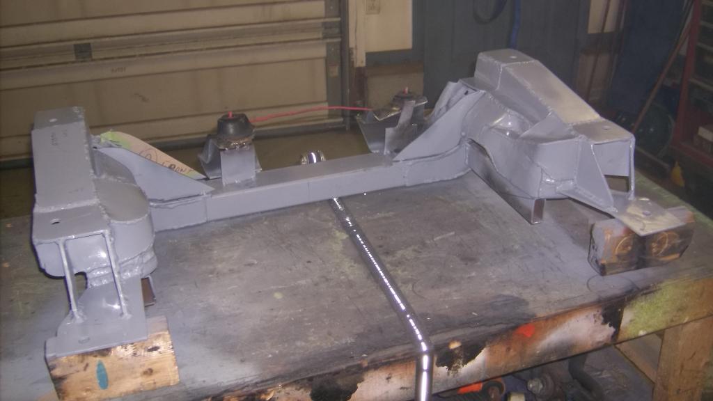
Here it is back in the car. The right side header was a tight fit and took several tries to get about 1/4 clearance.
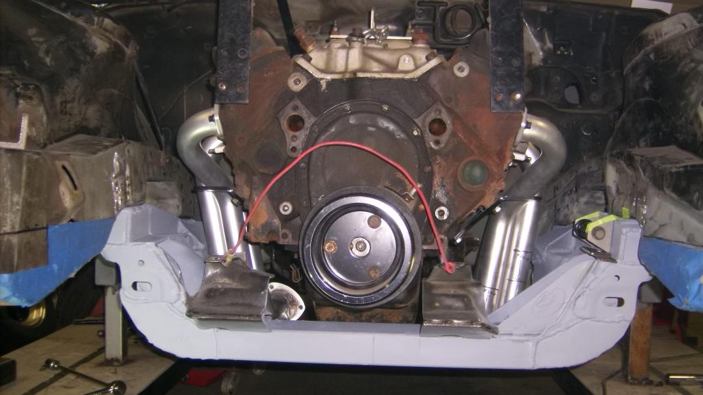
the gap above the k-member will eventually be plated over and k-member and frame all welded together.
Motor mounts will be simple urethane bushings in a 1 1/4 tube.

the gap above the k-member will eventually be plated over and k-member and frame all welded together.

Motor mounts will be simple urethane bushings in a 1 1/4 tube.

Thread Starter
Senior Member
Joined: Aug 2007
Posts: 682
Likes: 45
Re: Home brew road racer
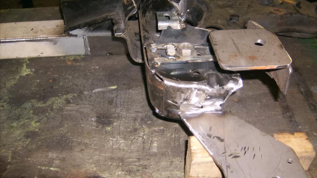
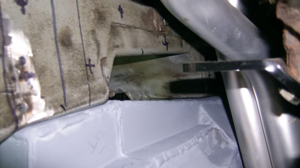
I picked up the adapter pieces for the ends of the steering rack today. Now I can get started on making a rack mount ahead of the engine and once the rack is in place design the extensions that will put the tie rods back in the stock location.
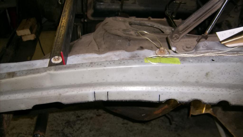
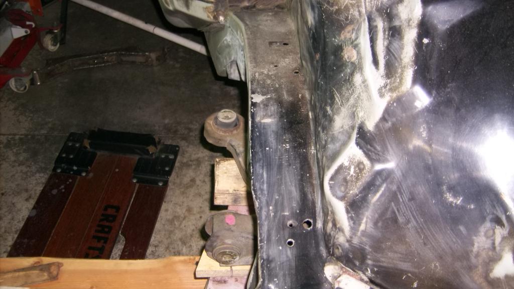
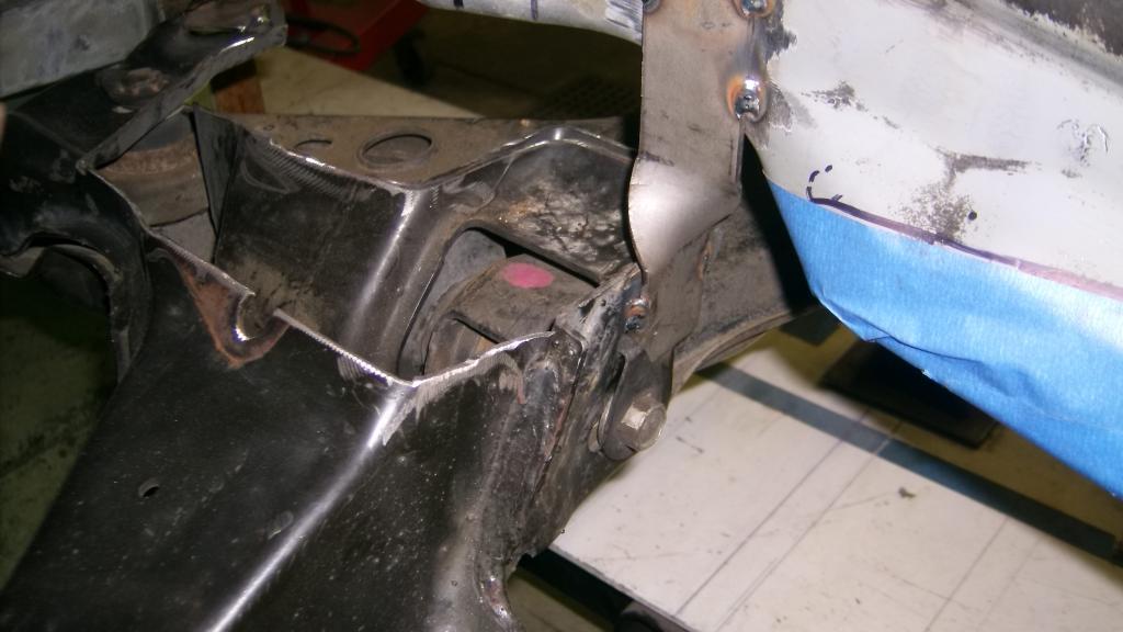
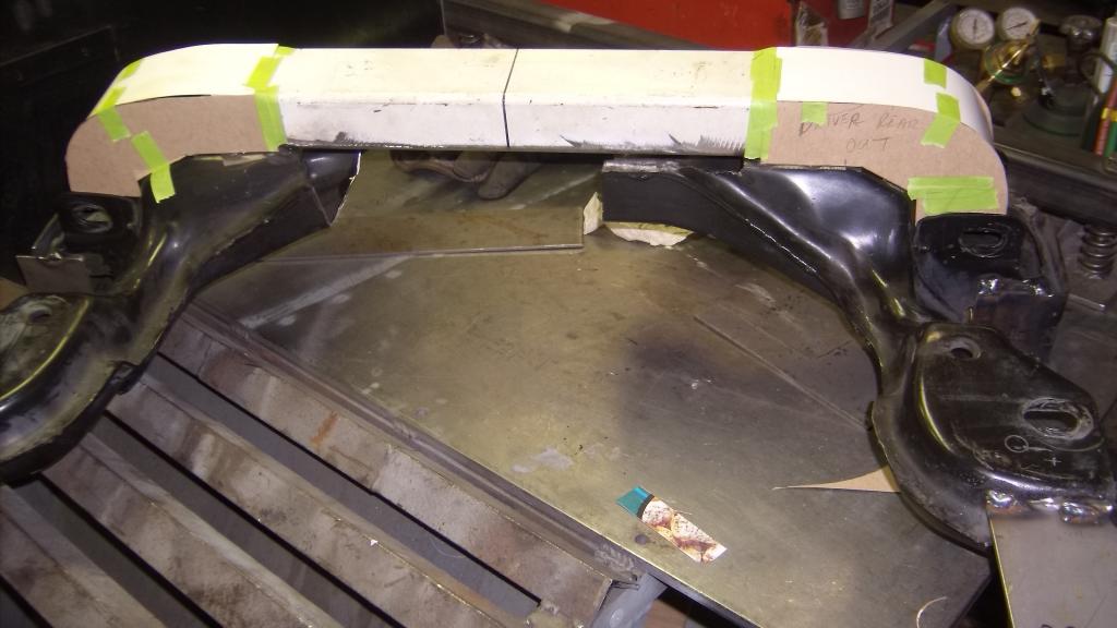
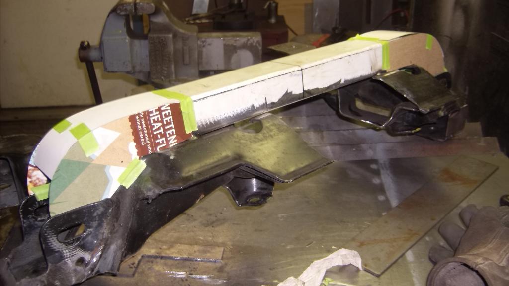
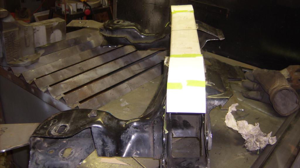
To mount the rack I will have to cut the front frame rails as they hang to low to clear the rack extensions. I have avoided cutting up the front frame till now but I am pretty sure I can make this all work so I will cut out the rails where the blue masking tape is. This will leave the rails in front of the engine about 4" high.
I will incorporate the splined sway bar mount into the front crossmember and the steering rack will mount to the crossmember as well. The crossmember will mount to the bottom of the shortened front rails.

Thread Starter
Senior Member
Joined: Aug 2007
Posts: 682
Likes: 45
Re: Home brew road racer
Propaint, thanks for following along. An aluminum block LS would be great but a lot more money. I had a lot of 350 performance parts from our stock car racing escapades so it made more sense to use that.
That being said the engine builder has finally started on my stroker build. he insisted that we swap out the steel I beam rods rated at 500hp for the H beam rods rated to 750hp. When I asked why he just said "you'll need them". Also the Brodix heads I got were used and I knew some of the guides were a little loose. The engine shop replaced all the guides and then replaced all the 2.020 intake valves with 2.050 valves.
It looks like the engine builder is looking to make a lot more HP than the 425/450 I was hoping for. I just cautioned him that the engine still has to be able to be streetable, has to idle and drive through town at 2000/2500 rpm.
Another drivetrain update. I have a line on a t56 trans and bellhousing that came out of a 1989 C4 Corvette. The car had been in storage and the building caught fire. Needless to say the fiberglass didn't hold up to well. A buddy of mine bought the drivetrain from the car last year to put in his 1969 Camaro but has since decided to go the LS route. he knew I was looking for a 5 or 6 speed and offered me the trans and bell for cheap. The t56 wasn't my first choice but a big improvement over the 4L60E I was going to use.