When you click on links to various merchants on this site and make a purchase, this can result in this site earning a commission. Affiliate programs and affiliations include, but are not limited to, the eBay Partner Network.
Re: GTA digital dash swap - doing it the hard way - pic heavy
The transistor is part of the interior lighting/dimmer. I was trying to bypass it, but you can't easily. It sounds like you may have a ground issue though
Re: GTA digital dash swap - doing it the hard way - pic heavy
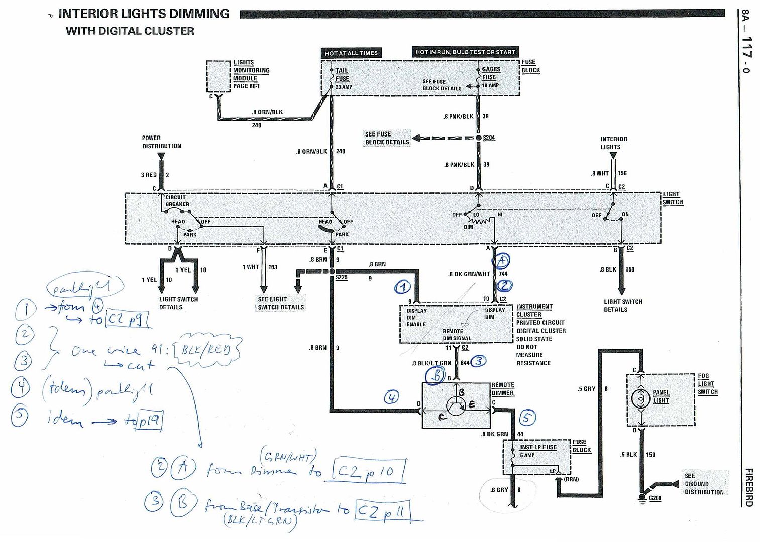
Managed to find a diagram focusing on this part. See attached.
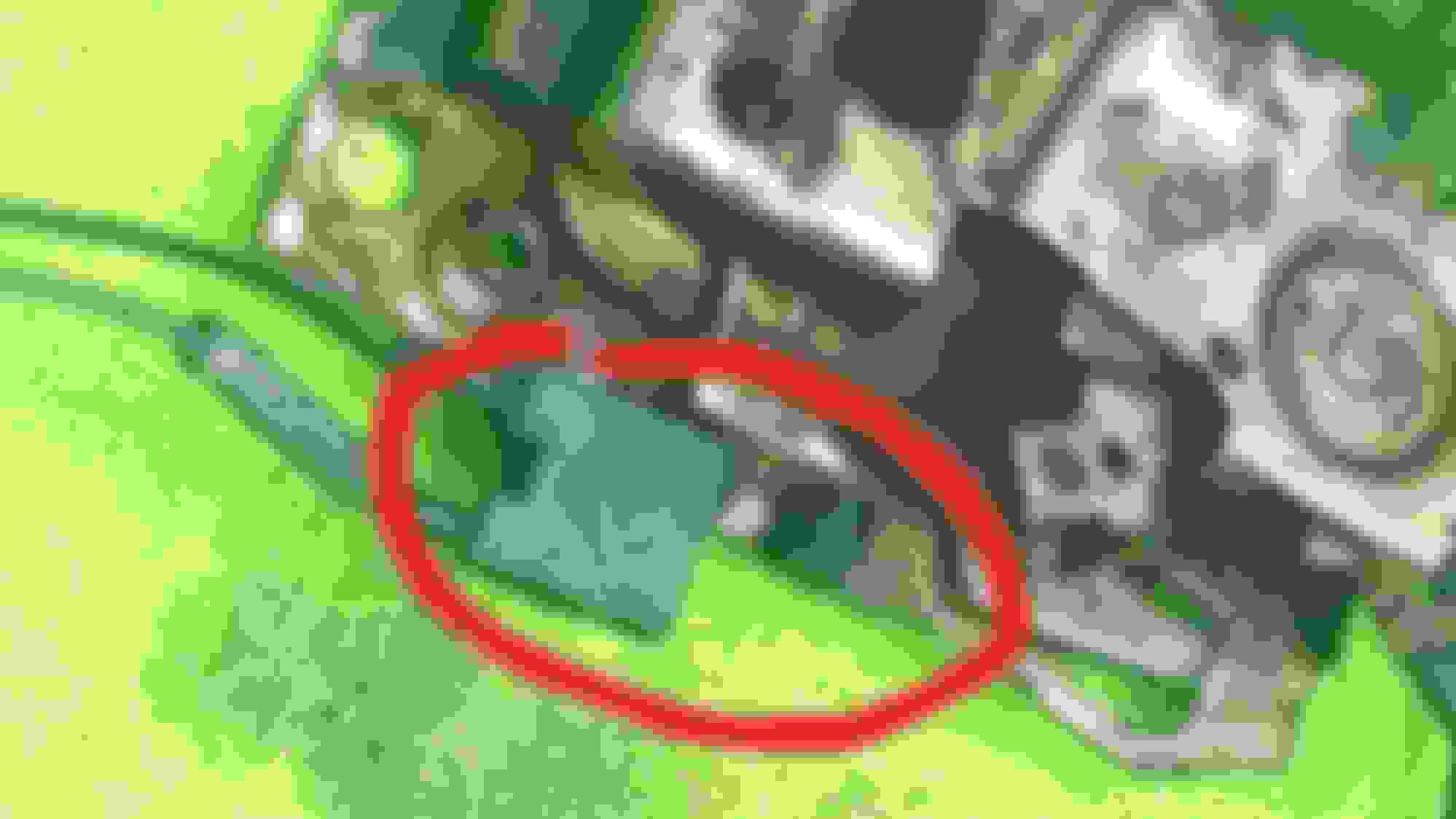
I did some more investigation. The Rheostat (Dimmer wheel) seems to be working fine as I got between 0 to 200 Ohms while turning and it.
I also ensured that the wiring to the transistor for the Light to the various instruments is fine. (See output C from transistor).
I also ensured transistor is getting 12v on D when light switch is on Park.
I could not find the third wire to B and have to make some more investigation.
I am sharing this information as I think it is helpful for others if/when they encounter the same thing.
I also checked the actual issue that led me here which is the reason why the Light switch light was not working (not sure about all the other lights yet) but for sure the transistor comes into play.
FYI, this strange looking bulb on top of the dimmer switch can actually be opened and I guess the internal bulb can be replaced with a normal 12v bulb. See picture. Mine was blown so even if I fix the transistor it wouldn't have worked .
Re: GTA digital dash swap - doing it the hard way - pic heavy
I read somewhere that it was a neon bulb so I didn’t know if you could power it off normal 12VDC. Still I don’t have output to other switch illuminations so although this bulb is blown, I still need to sort out the root cause.
Do you happen to know what kind of bulb this is?
Sorry to hijack your thread Cehbra. My original request was re the dash shell connector.
Re: GTA digital dash swap - doing it the hard way - pic heavy
FYI, in Digital Dash installations, the signal wire from the rheostat to the transistor is not as per the diagram that I attached above. It doesnt go straight to ping B of the transistor but goes to the dash connector (not the black/grey one) and then to the transistor. I am assuming this is because the digital dash needs the non-amplified dimmer signal to adjust its illumination.
I have taken the digital dash apart and found that slimey foam sort of tape. Do you guys think I can simply clean it off and work without it?
Re: GTA digital dash swap - doing it the hard way - pic heavy
Aseychell, here are some answers:
As for the connector orientation: both connectors go in horizontally. Just look at the (very small) numbers on the pins. The row with the higher numbers (pin 18 to 34) is on top.
Re: GTA digital dash swap - doing it the hard way - pic heavy
Originally Posted by aseychell
I have taken the digital dash apart and found that slimey foam sort of tape. Do you guys think I can simply clean it off and work without it?
I noticed that degenerating foam as well. What I did is I made a new one out of some ESD foam. In case you want to do that as well I attached a scan to trace it.
Not sure, if it's a good idea to go without it as I'm sure that foam helps reducing vibration to the LCDs
Re: GTA digital dash swap - doing it the hard way - pic heavy
Originally Posted by Davidgou
Wow Cehbra, awesome work. Your video looks great! Congratulations! My original digital dash switched to KM or Miles on the odometer as well. I replaced it with a Canadian dash and it works the exact same way.
Thanks for that info. I hope I will find some time to get to the bottom of why mine don't switch the speedo section.
Re: GTA digital dash swap - doing it the hard way - pic heavy
As always your information is bang on
Will try to see if I can find someone locally who can cut this foam. The thinnest I managed to find is 6mm which I think is a bit too excessive but will try it out. Have to see how to glue it also.
Re. the bulbs, I decided to keep them incandescent and will be replacing them just to start their lifetime again. I really need to close this dash off and start assembling the rest as its been more than 2 yrs on this car now and honestly I need to see it ready
Re: GTA digital dash swap - doing it the hard way - pic heavy
Originally Posted by Cehbra
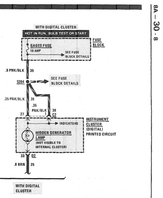
@aseychell: I went through the schematics and I found this in the 1988 service manual, see below. The bulb on pin 33 (behind the pressure gages) is not for illuminating but for the generator, so this has to stay a bulb and should not be exchanged for an LED! The current through the generator lamp is necessary to start producing power. An LED may not pass enough current to start that process without additional resistors.
Can anyone confirm if this is the location of the generator lamp? (On the PCB for the pressure gauges.)
Re: GTA digital dash swap - doing it the hard way - pic heavy
I'm currently preparing to swap a digital dash into my '91 convertible and have been using this thread very successfully as a guide. I'm very clueless and I'm left with a question on what to do with:
-Lights On Input (C2 pin 9)
-Display Dim IN (C2 pin 10)
-Display Dim OUT (C2 pin 11)
-Illumination output to DIC/Panel Lights Return (C2 pin 14)
-"Memory input" to odometer RAM (C2 pin 21)
-Illumination input from I-P/Panel lights return (DIC pin B)
-Interior lights dimming (DIC pin E)
All of the above, I don't know what they are, what they do, or what I should do with them. For simplicity's sake, I've decided against hunting down and wiring the various sensors throughout the car. Rather, I'm going to get only the 3 main parts of the dash lit up and functional for the time being. The carpet needs replaced and the floors need work so it'll all be coming out eventually, so I'll revisit the sensors then.
Re: GTA digital dash swap - doing it the hard way - pic heavy
Originally Posted by Paintchips97
I'm currently preparing to swap a digital dash into my '91 convertible and have been using this thread very successfully as a guide. I'm very clueless and I'm left with a question on what to do with:
-Lights On Input (C2 pin 9)
-Display Dim IN (C2 pin 10)
-Display Dim OUT (C2 pin 11)
-Illumination output to DIC/Panel Lights Return (C2 pin 14)
-"Memory input" to odometer RAM (C2 pin 21)
-Illumination input from I-P/Panel lights return (DIC pin B)
-Interior lights dimming (DIC pin E)
All of the above, I don't know what they are, what they do, or what I should do with them. For simplicity's sake, I've decided against hunting down and wiring the various sensors throughout the car. Rather, I'm going to get only the 3 main parts of the dash lit up and functional for the time being. The carpet needs replaced and the floors need work so it'll all be coming out eventually, so I'll revisit the sensors then.
Cool to see that there are more people interested in the digital dash!
Here are some answers from what I recall:
The "lights on input" is used to dim the dash illumination when it's dark outside, so the driver won't get blinded by the bright lights of the dash. Instead of an ambient light sensor the dash simply assumes that it's dark outside when the head lights are turned on. So you just give +12 V on that pin from the light switch or just omit it all together, in reality it doesn't do very much...
The "Illumination output to DIC/Panel Lights Return" is just a direct wire to pin B from the DIC, where it synchronizes the brightness. So just connect DIC pin B to pin 14 on C2 from the dash and that's it.
"Memory input" is a mandatory +12 V 'always hot' wire for the odometer. The precise mileage is stored in the RAM of the microcontroller and dumped to the EEPROM only every 10 miles. So if you completely lose power to the odometer when the engine switches off you would revert the mileage to the last 5 miles each time. See https://www.thirdgen.org/forums/elec...o-86-88-a.html
The Display Dim in / out pin as well as the interior lights dimming pin on the DIC are somewhat tricky, I'll need to look into my schematics to tell you exactly how that goes. I remember I had to cut a wire to that fat transistor from the interior lights dimming. I'll look it up later
Re: GTA digital dash swap - doing it the hard way - pic heavy
Originally Posted by Cehbra
Cool to see that there are more people interested in the digital dash!
Here are some answers from what I recall:
The "lights on input" is used to dim the dash illumination when it's dark outside, so the driver won't get blinded by the bright lights of the dash. Instead of an ambient light sensor the dash simply assumes that it's dark outside when the head lights are turned on. So you just give +12 V on that pin from the light switch or just omit it all together, in reality it doesn't do very much...
The "Illumination output to DIC/Panel Lights Return" is just a direct wire to pin B from the DIC, where it synchronizes the brightness. So just connect DIC pin B to pin 14 on C2 from the dash and that's it.
"Memory input" is a mandatory +12 V 'always hot' wire for the odometer. The precise mileage is stored in the RAM of the microcontroller and dumped to the EEPROM only every 10 miles. So if you completely lose power to the odometer when the engine switches off you would revert the mileage to the last 5 miles each time. See https://www.thirdgen.org/forums/elec...o-86-88-a.html
The Display Dim in / out pin as well as the interior lights dimming pin on the DIC are somewhat tricky, I'll need to look into my schematics to tell you exactly how that goes. I remember I had to cut a wire to that fat transistor from the interior lights dimming. I'll look it up later
Awesome, I really appreciate it. I'm almost set now. Gotta do some more research on which grounds are which (G118 and G200), and button up the Display Dim in/out and interior lights dimming and I'll be set. Ran the orange constant 12v for the odometer last night before I laid down for bed.
This thread has been invaluable to me doing this swap. I never would have attempted anything otherwise. Keep up the great work!
Re: GTA digital dash swap - doing it the hard way - pic heavy
Originally Posted by Paintchips97
Awesome, I really appreciate it. I'm almost set now. Gotta do some more research on which grounds are which (G118 and G200), and button up the Display Dim in/out and interior lights dimming and I'll be set. Ran the orange constant 12v for the odometer last night before I laid down for bed.
This thread has been invaluable to me doing this swap. I never would have attempted anything otherwise. Keep up the great work!
All right, here are some more things on the interior lights dimming with the digital dash. For the dimming of the interior lights Pontiac used a large transistor with a heat sink, you will find this device under your dash. In 1988 it was wired a little different than in 1991, here are the differences:
Re: GTA digital dash swap - doing it the hard way - pic heavy
As you can see, in 1988 the digital dash is mounted in between the potentiometer and the base of the transistor (GM 10029920, transistor is a Motorola 1986902-1 model). Thus you will have to cut that black/red wire in your 1991 Firebird. The two ends then are connected as follows:
- wire from the potentiometer wheel goes to C2 pin 10 (display dim IN)
- wire from the base of the transistor goes to C2 pin 11 (display dim OUT)
Re: GTA digital dash swap - doing it the hard way - pic heavy
The gray wire from the emitter of the transistor will go to C2 pin 19 (interior lights dimming), this is the reduced voltage from the dimming wheel. Not surprisingly it also goes to pin E on the DIC as it has the same function there.
Re: GTA digital dash swap - doing it the hard way - pic heavy
Side note: the difference between 1988 and 1991 or better: between digital and analog dash is mainly, that in the analog dash you'll get current to the dimmer only when the exterior lights are switched on. The reason is that there is no illumination necessary in daylight condition. However the digital dash needs an illumination all the time.
Re: GTA digital dash swap - doing it the hard way - pic heavy
Originally Posted by Cehbra
The gray wire from the emitter of the transistor will go to C2 pin 19 (interior lights dimming), this is the reduced voltage from the dimming wheel. Not surprisingly it also goes to pin E on the DIC as it has the same function there.
I hate to keep pestering with questions but this has been far out of my realm, so far that this project taught me what a remote dimmer switch was, if that tells you anything. I have everything done except for the interior lights dimming. Is there any way you can describe the transistor emitter? There's 3 wires coming from my transistor, black/red, green, and brown, in B, C, and D, respectively. Once I find out exactly where to tie that in, I'll be in the home stretch, I believe. I'll post pictures as soon as possible, my phone won't allow it.
Re: GTA digital dash swap - doing it the hard way - pic heavy
Originally Posted by Paintchips97
I hate to keep pestering with questions but this has been far out of my realm, so far that this project taught me what a remote dimmer switch was, if that tells you anything. I have everything done except for the interior lights dimming. Is there any way you can describe the transistor emitter? There's 3 wires coming from my transistor, black/red, green, and brown, in B, C, and D, respectively. Once I find out exactly where to tie that in, I'll be in the home stretch, I believe. I'll post pictures as soon as possible, my phone won't allow it.
No problem! Basically a transistor works like a pipe connecting a source of water to a drain with a controllable valve across a section of the pipe. By controlling whether the valve (in a transistor this is the base B) is fully closed, fully open, or partially open, you control the flow of water from the source (collector C) to the drain (emitter E).
In our cars this is used to run a small current through the dimmer potentiometer that controls (B) the large current (C->E) needed for the light bulbs of the interior like the dash lights, HVAC, map light and all the button lights. If you'd control the current to all those lights directly with the dimmer wheel this would require a large and expensive potentiometer.
In the 1991 model year with the analog dash the emitter is the gray wire carrying the large current that directly controls all the interior lights. At daytime you can switch the lights off. However in the digital dash you won't see anything when the backlights are off, so the dash needs control over the "valve" and therefore the current from the dimmer potentiometer is directed through the dash first.
Re: GTA digital dash swap - doing it the hard way - pic heavy
Long story short: The transistor has three wires:
- Base: pin B, black/red wire
- Collector: pin D, brown wire
- Emitter: pin C, dark green, and gray down the line
All you have to do is cut the black/red wire. You'll be left with two ends. The one that connects to the transistor needs to go to C2 pin 11 (display dim OUT). The other end goes to C2 pin 10 (display dim IN). See also the schematics in post 219.
You can leave the brown and green wires as they are.
Re: GTA digital dash swap - doing it the hard way - pic heavy
Well, I'm not sure what I've done wrong, but my DIC and odometer light up nice and bright but I can't get light to the gauge cluster itself, nor is my shift indicator lighting up. I think I may be in some trouble, lol.
Re: GTA digital dash swap - doing it the hard way - pic heavy
Yeah, I went with bright white LEDs. The gauges appear much more green in person rather than the blue that shows up in photos. I have some progress pics, but most are in the temporary wire nut stage because I got in a hurry when it came time to put the dash carrier in! Lol
Re: GTA digital dash swap - doing it the hard way - pic heavy
wow! So thrilled that you posted this......Have an '88 GTA Digital dash. Was wonderin' why my LD ajar was always indicated "Open" on the D.I.C.
I assumed it was a sensor/wiring issue. Finally pulled off the door panel and took the door lock actuator out to have a look. The door Ajar sensor/switch broke off the actuator.
This seems to be an uncommon part, and I assume will be extremely hard to locate a new one given the rarirty of this year and model of Firebird (Digital Dash)...any leads on where I can find a new switch/sensor. You posted the part numbers which is great but I have no luck on finding these parts on the 'net.
Re: GTA digital dash swap - doing it the hard way - pic heavy
Originally Posted by Cehbra
And this is the digital HVAC harness:
I'm doing a similar project you right now and I've pretty much been picking through the harness for everything I need to swap it over into mine but everything so far has been straightforward for the most part but I was curious how did you end up swapping in the plugs and wires for the electric vacuum controls on the right side of the HVAC assembly? Being that they are embedded into the main harness of the digital set up did you end up delooming that digital harness to remove the connectors and wires needed and then run them through your 91 harness? If not how did you go about doing it?
Re: GTA digital dash swap - doing it the hard way - pic heavy
Originally Posted by Cehbra
And this is the digital HVAC harness:
I was wondering if you could tell me what vacuum lines from the inside on the heater box connected to the vacuum lines that goes through the firewall to the engine because your picture is the best representation of the HVAC harness for the digital climate control that I seen yet yes I still can't zoom in close enough to see in the detail that I need to grasp what connects to where
Re: GTA digital dash swap - doing it the hard way - pic heavy
Originally Posted by Dual86TA
I was wondering if you could tell me what vacuum lines from the inside on the heater box connected to the vacuum lines that goes through the firewall to the engine because your picture is the best representation of the HVAC harness for the digital climate control that I seen yet yes I still can't zoom in close enough to see in the detail that I need to grasp what connects to where
Looks like the engine vacuum source goes to that smaller connector on the RH side and then it works the water bypass under the hood. There's only two connections inside the car
Re: GTA digital dash swap - doing it the hard way - pic heavy
I am on the verge of buying an 88 with the digital dash. The dash seems to work fine from what I can tell but also looks a little dim.
My question is if there is an easy fix for making it brighter? Whether it be switching bulbs or something like that. I tried to read this thread to find the answer but I�m not very mechanically inclined. You might have to explain it like I�m 5.
Re: GTA digital dash swap - doing it the hard way - pic heavy
@Cehbra I have a question for you sir. I just bought a fixer upper. It�s an 86 without the digital dash and it�s an automatic. My goal is to put a manual transmission in with a digital dash. Took it off someone hands for super cheap and I always wanted a little project car.
1) Anyways the question is is the orange square in the top left of the dash is for the displaying what gear the car is in correct?
2) If so, in your experience would it make more sense to try and instal the manual transmission before the digital dash? 3)
And is there a special sensor I need to look for on the internet?
I know many will say just buy a manual or buy one with digital dash. That�s just not an option right now for me. I got this car for $200 and am looking forward to making her pretty again.


 .
.